

Hello to all the inhabitants of our sites. Many hams know that a power supply is an expensive part of all electronics and often it’s not possible to get a good power supply, but every beginner who understands the radio part has an old computer unit that has long been left behind and has not been used. In this article I will tell you how to make a laboratory power supply for various devices, such as, for example, an amplifier.
First you need to decide what you need to build, this:
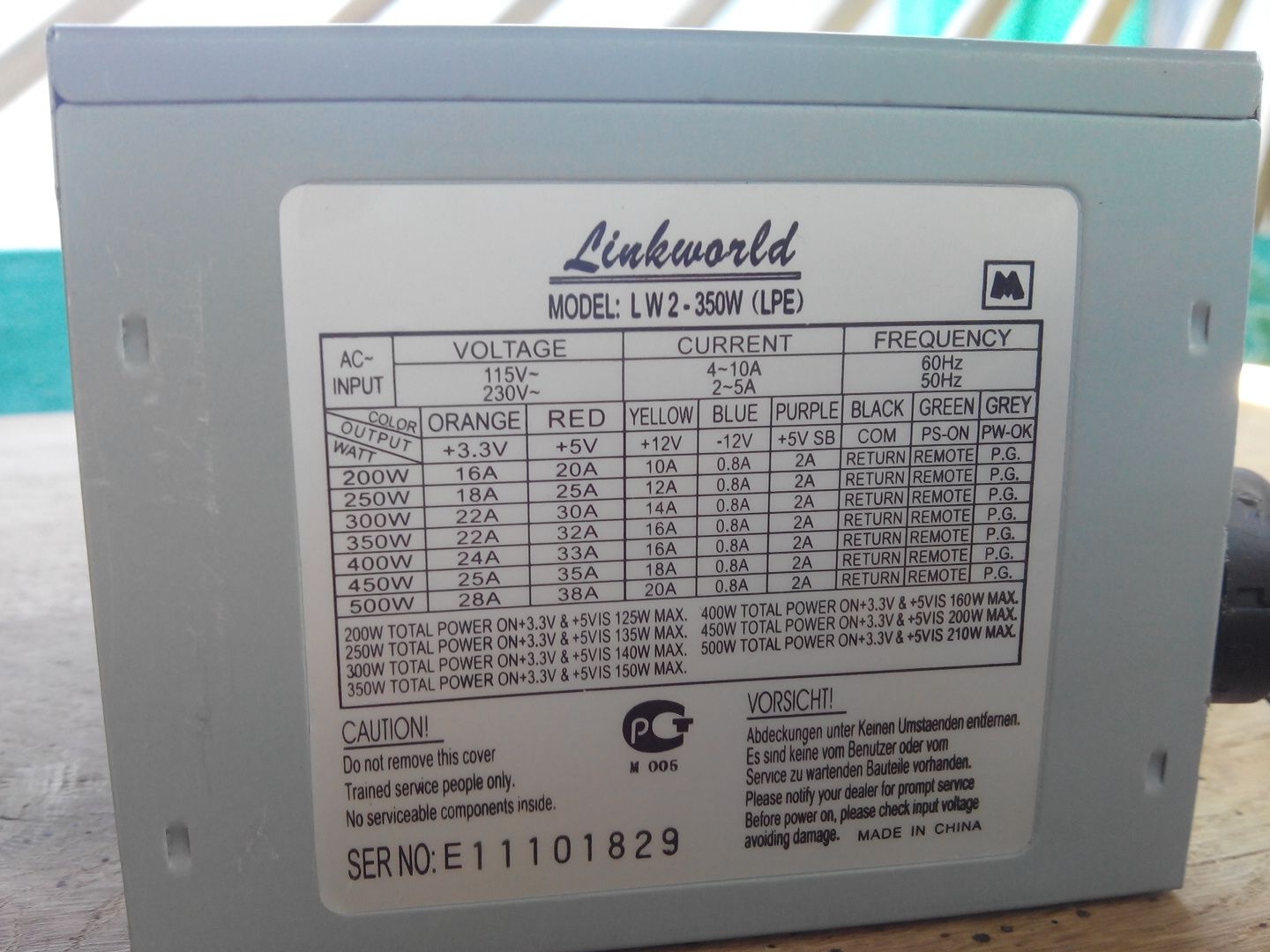
* The computer unit itself, my power was 350 watts, which is enough for everything with a margin.
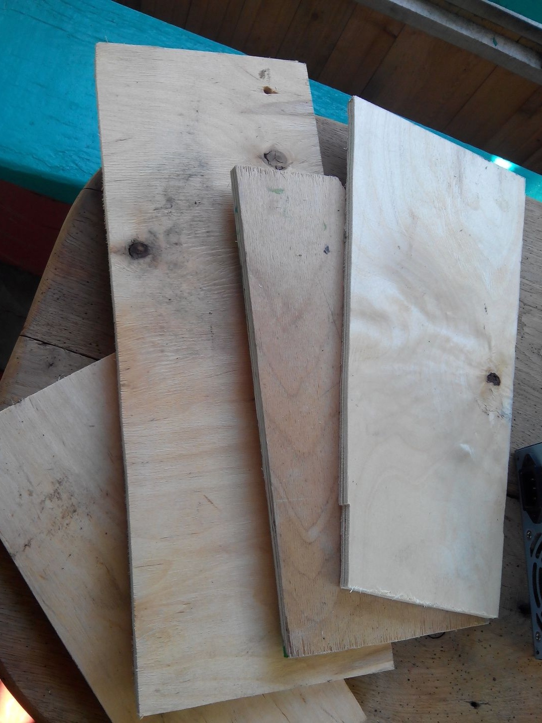
* Plywood, I have 4 segments.
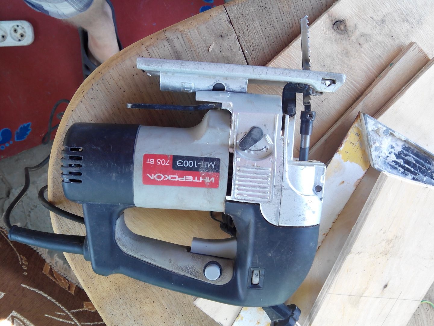
* Electric fretsaw.
* Screwdrivers.
* Soldering iron and soldering accessories.
* Drill.
* Sandpaper, larger grain size.
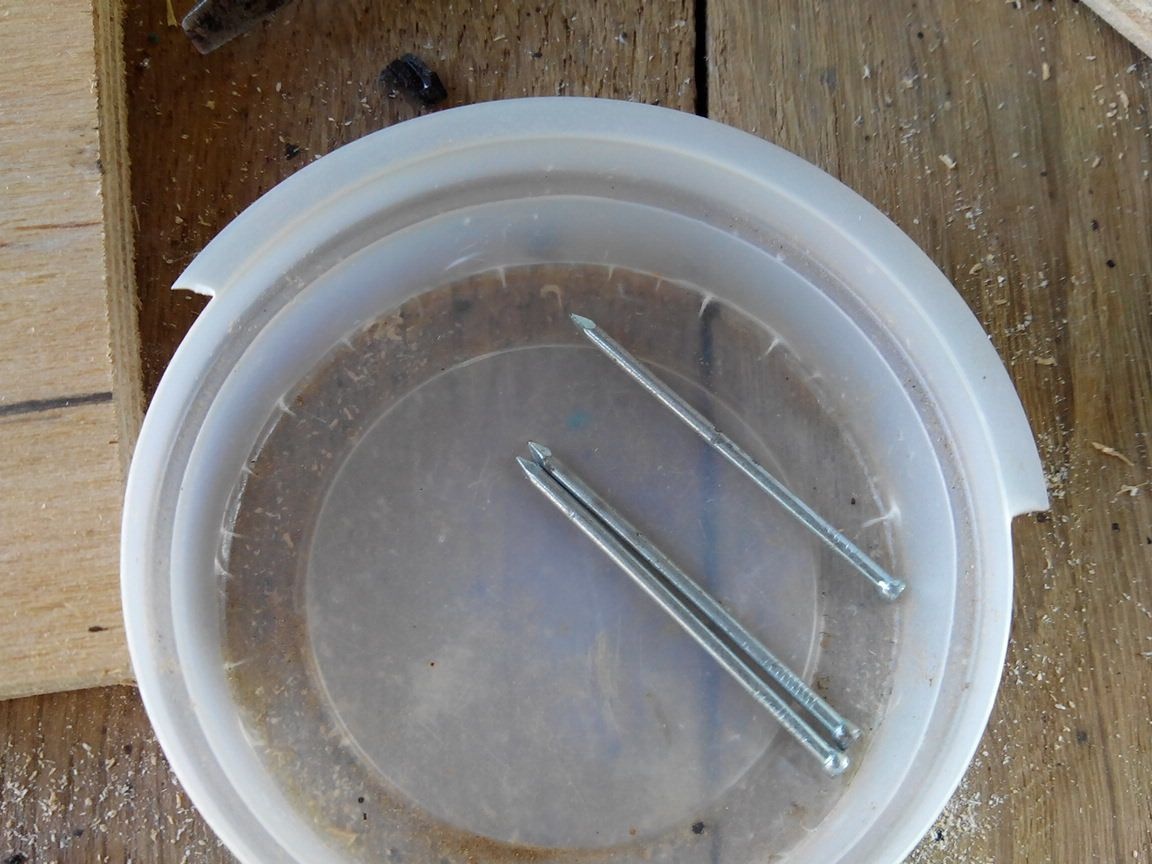
* Nails, I preferred nails with a small hat.
* Rubber plugs extracted from chemical test tubes.
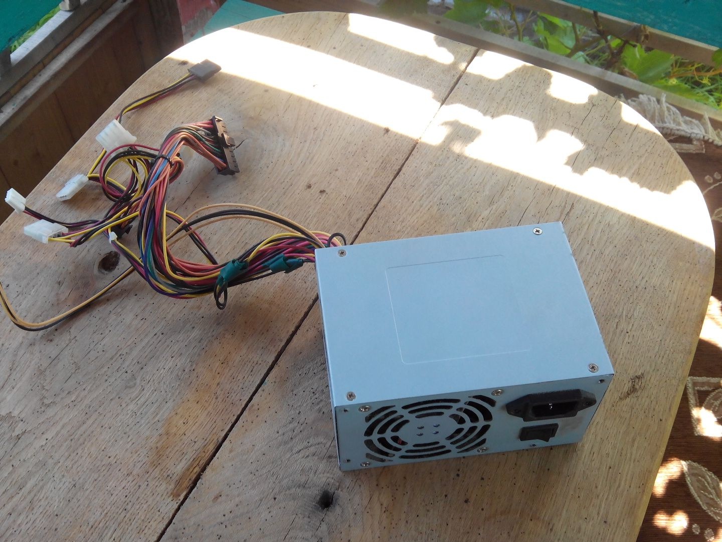
When you have everything you need, you can begin to disassemble the computer power supply.
First, unscrew the top bolts that hold the cover.
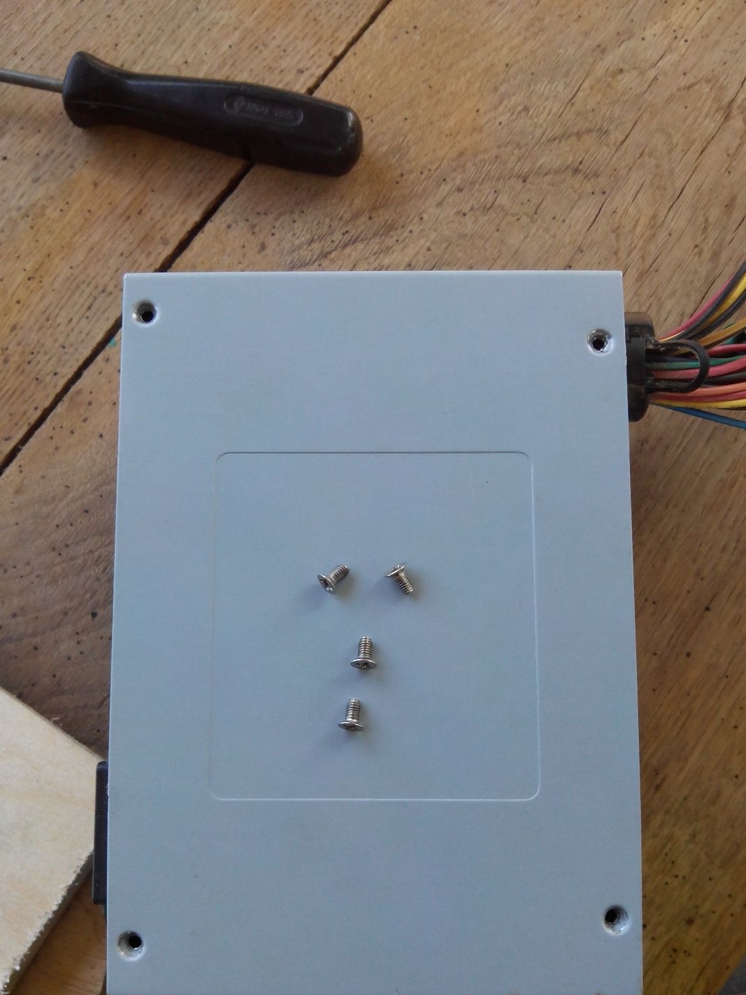
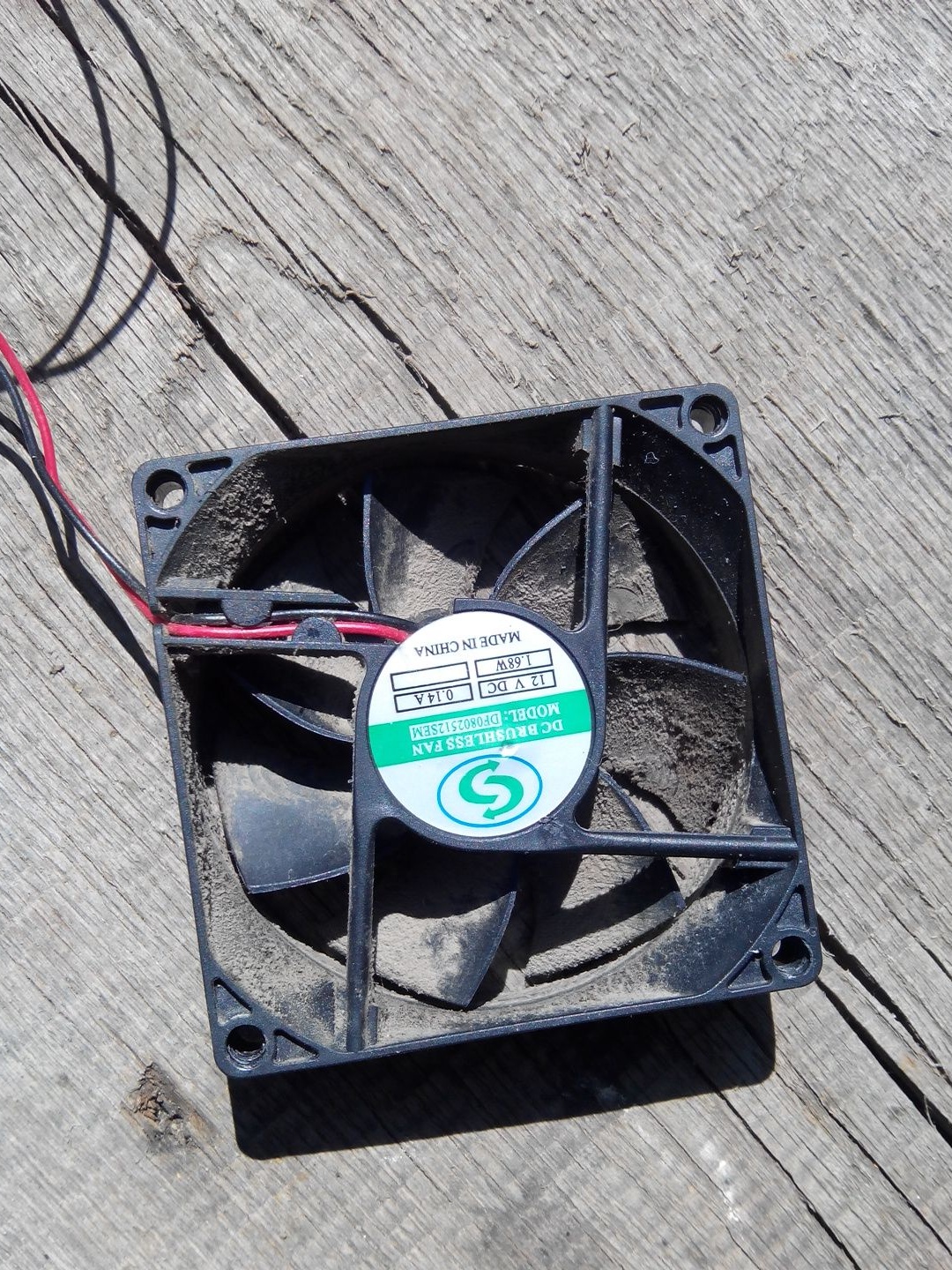
Unscrewing them, go to the four bolts on the cooler.
After that, we will free the board from the case, there are also bolts there, in my case there is still one black bolt hidden in the middle, which I did not notice at first.
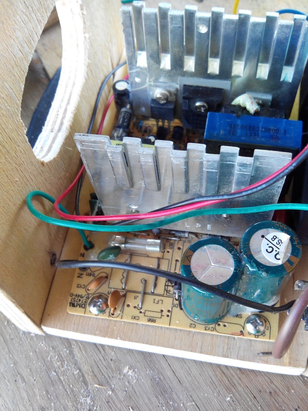
But, as it turned out, the board can not be pulled out like this, you need to solder the wires from the connection to the 220V power input. Be careful, nearby capacitors may not yet be discharged and give out a little bit of such a high voltage current.
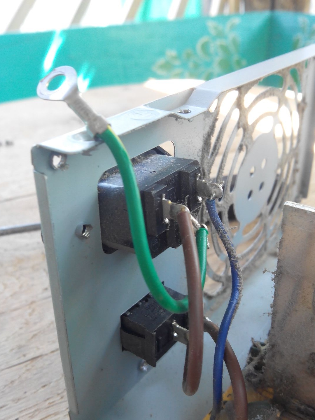
We also solder the wires from the switch.
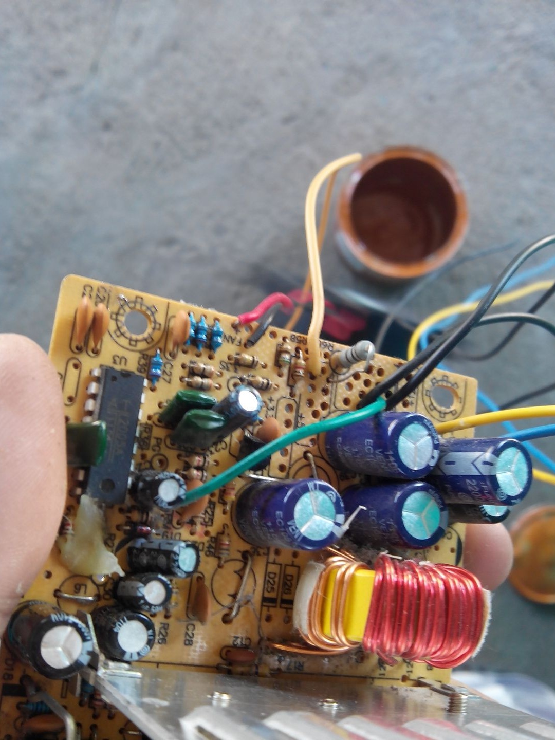
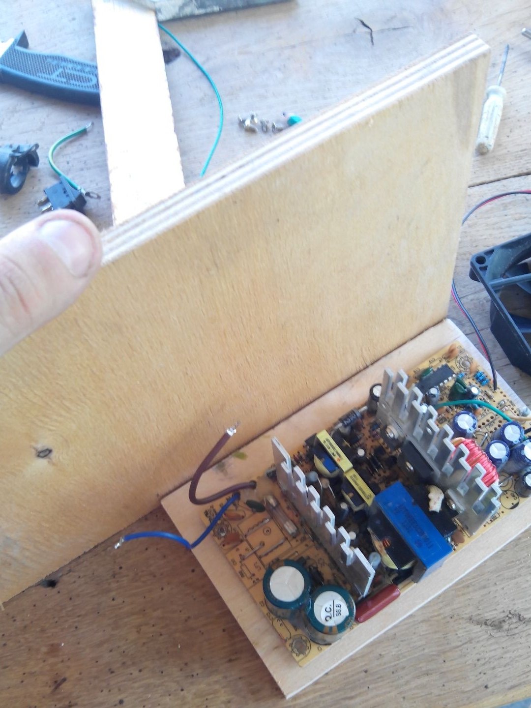
Now the unit board is easily removable, and
the native building is no longer useful to us.
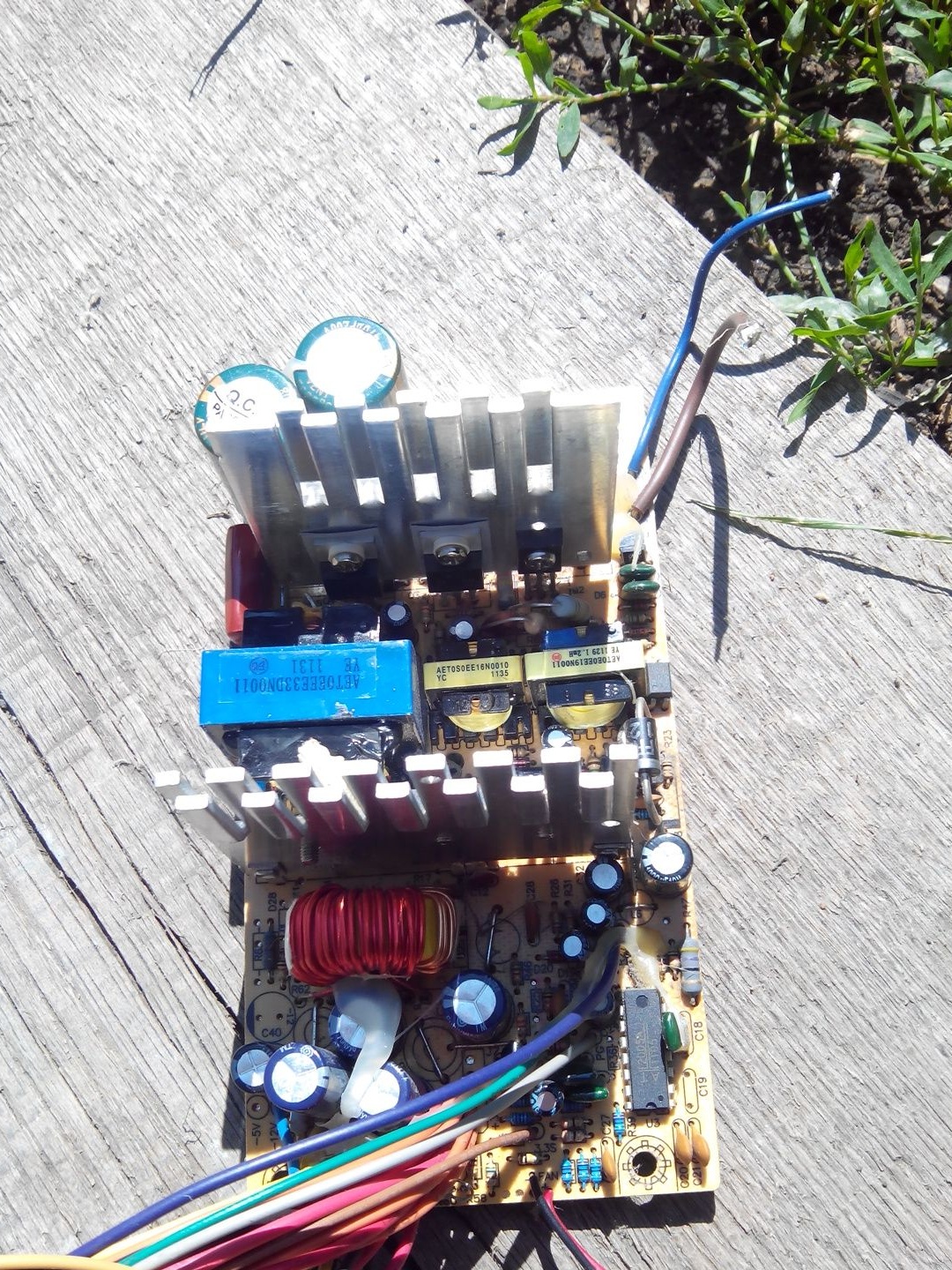
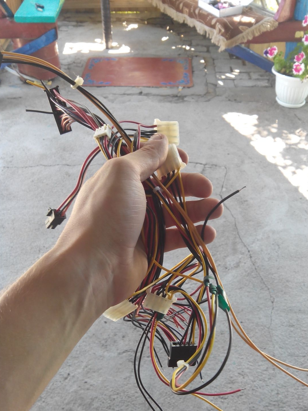
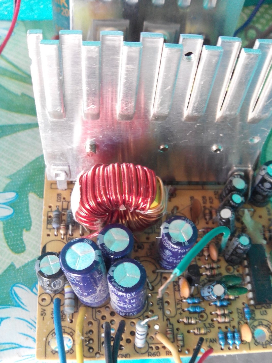
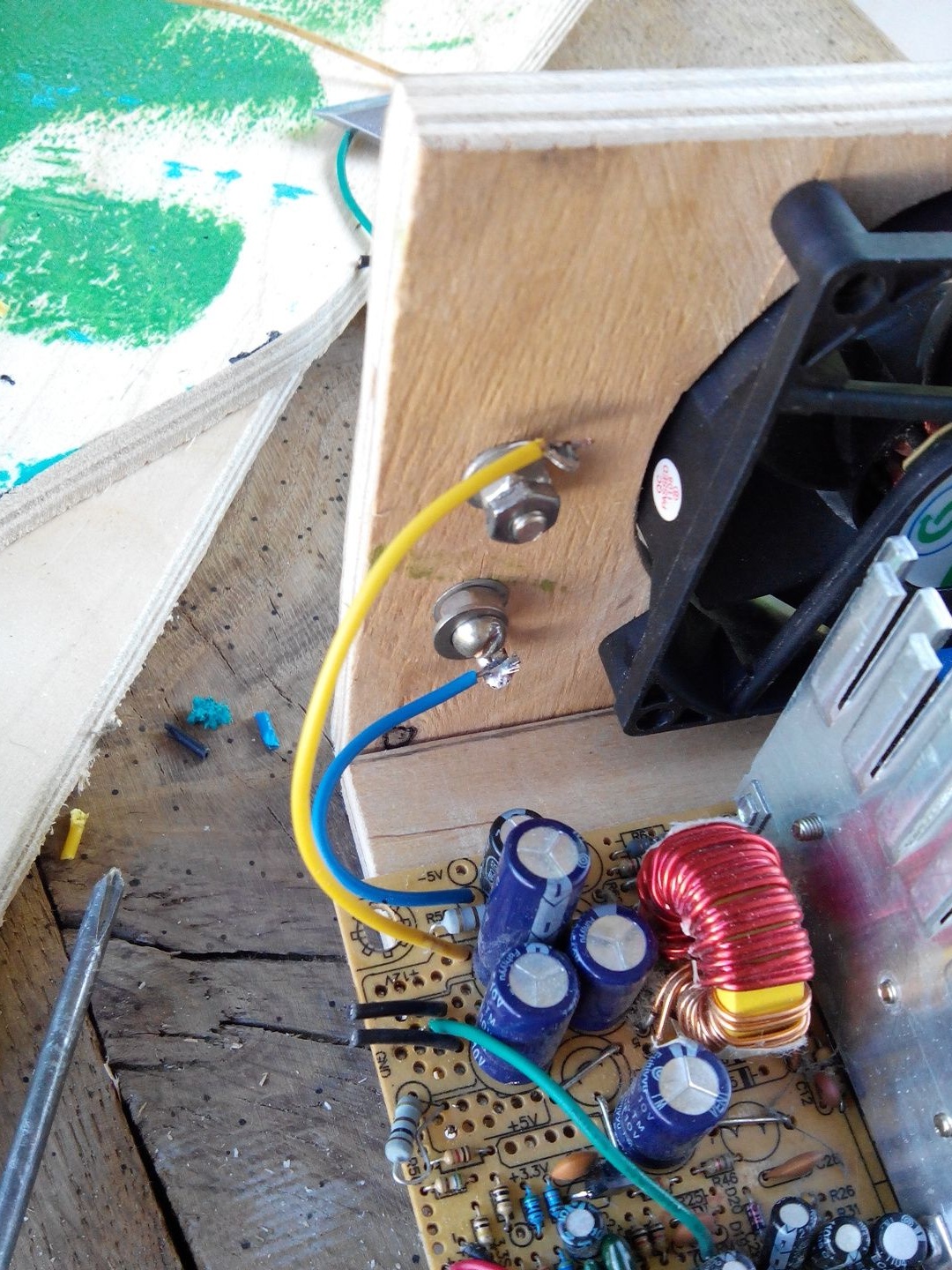
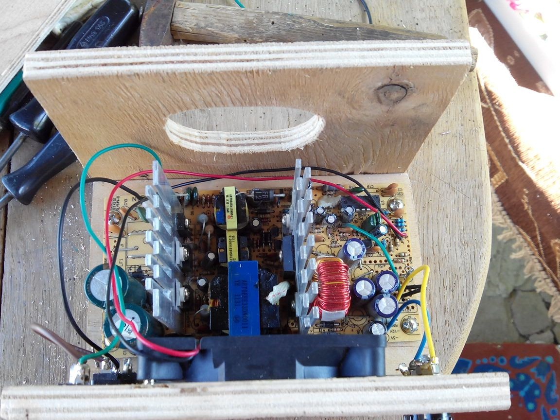
The next thing we remove from the block will be a bunch of wires, since we will need only 3 of them, this is yellow (12V +) and blue (-) and green to turn on.
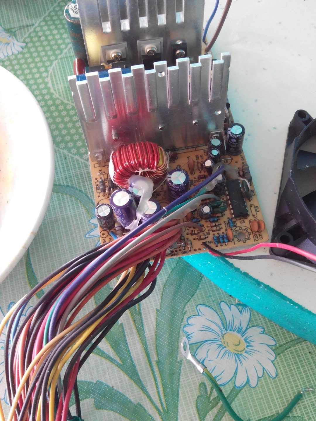
In order for the unit to turn on the green wiring, we solder to the place of accumulation of black wires.
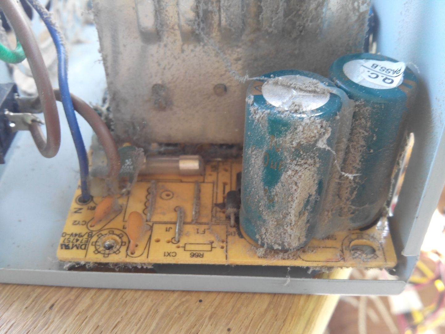
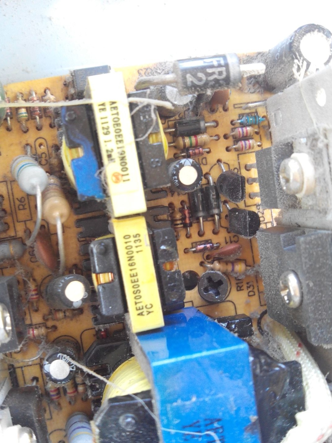
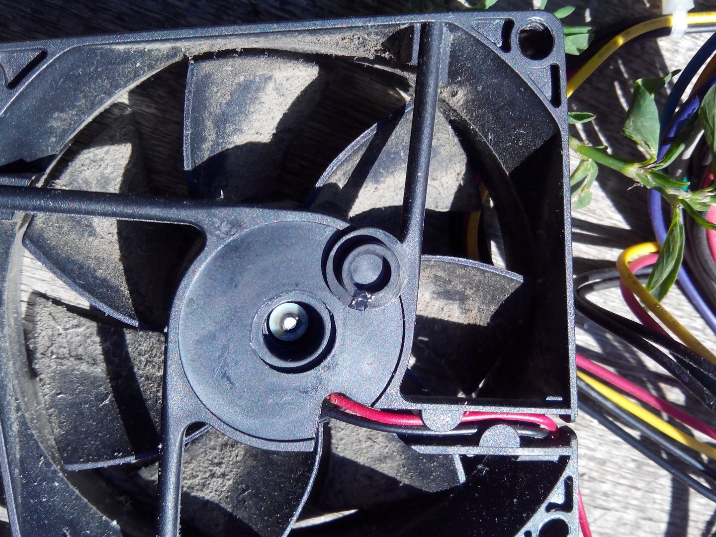
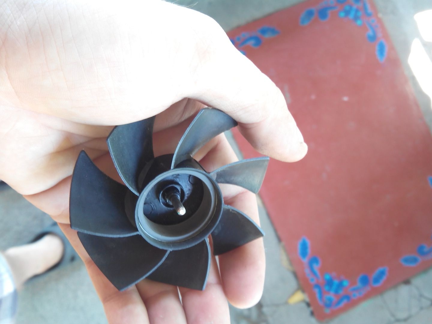
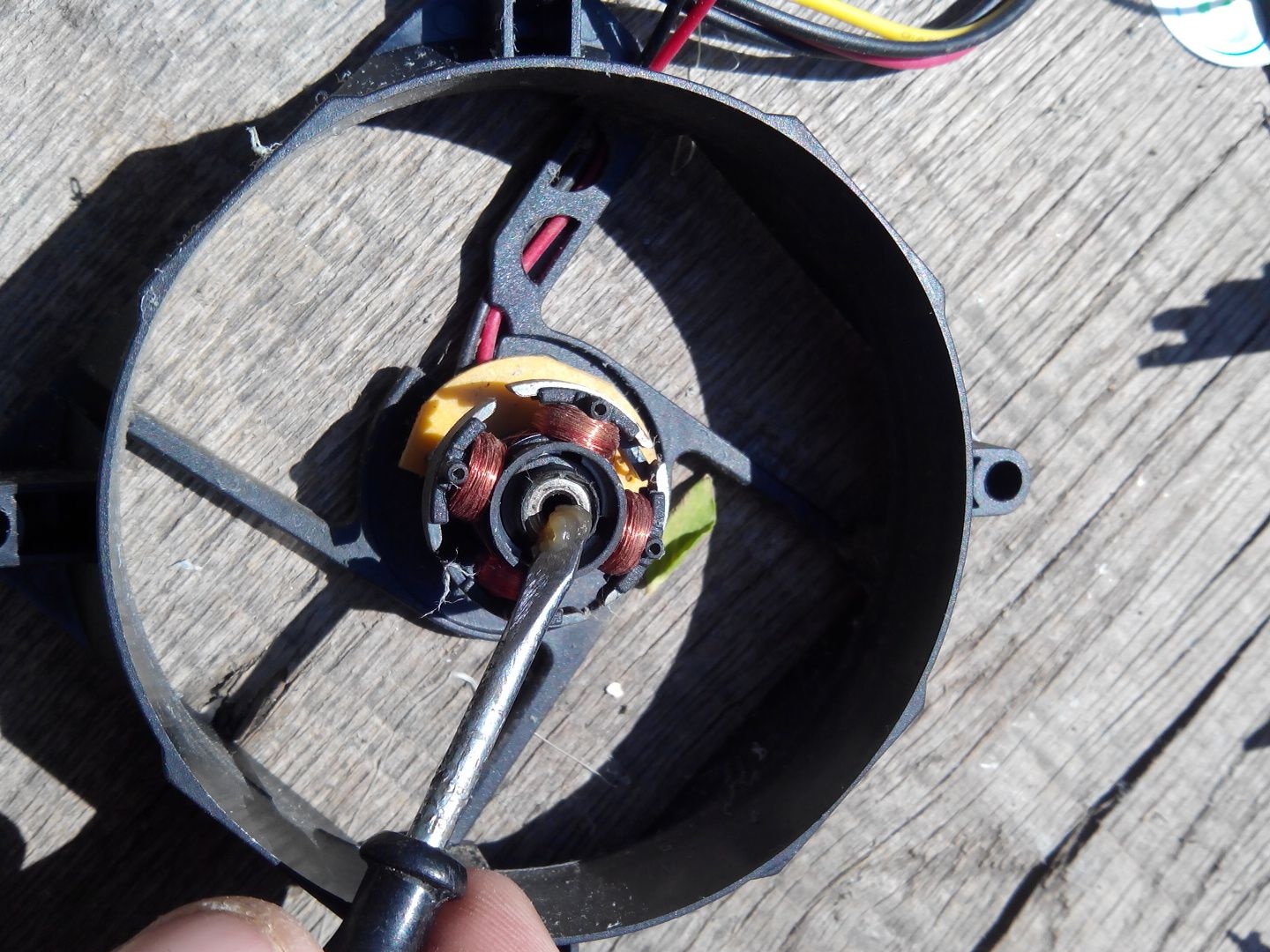
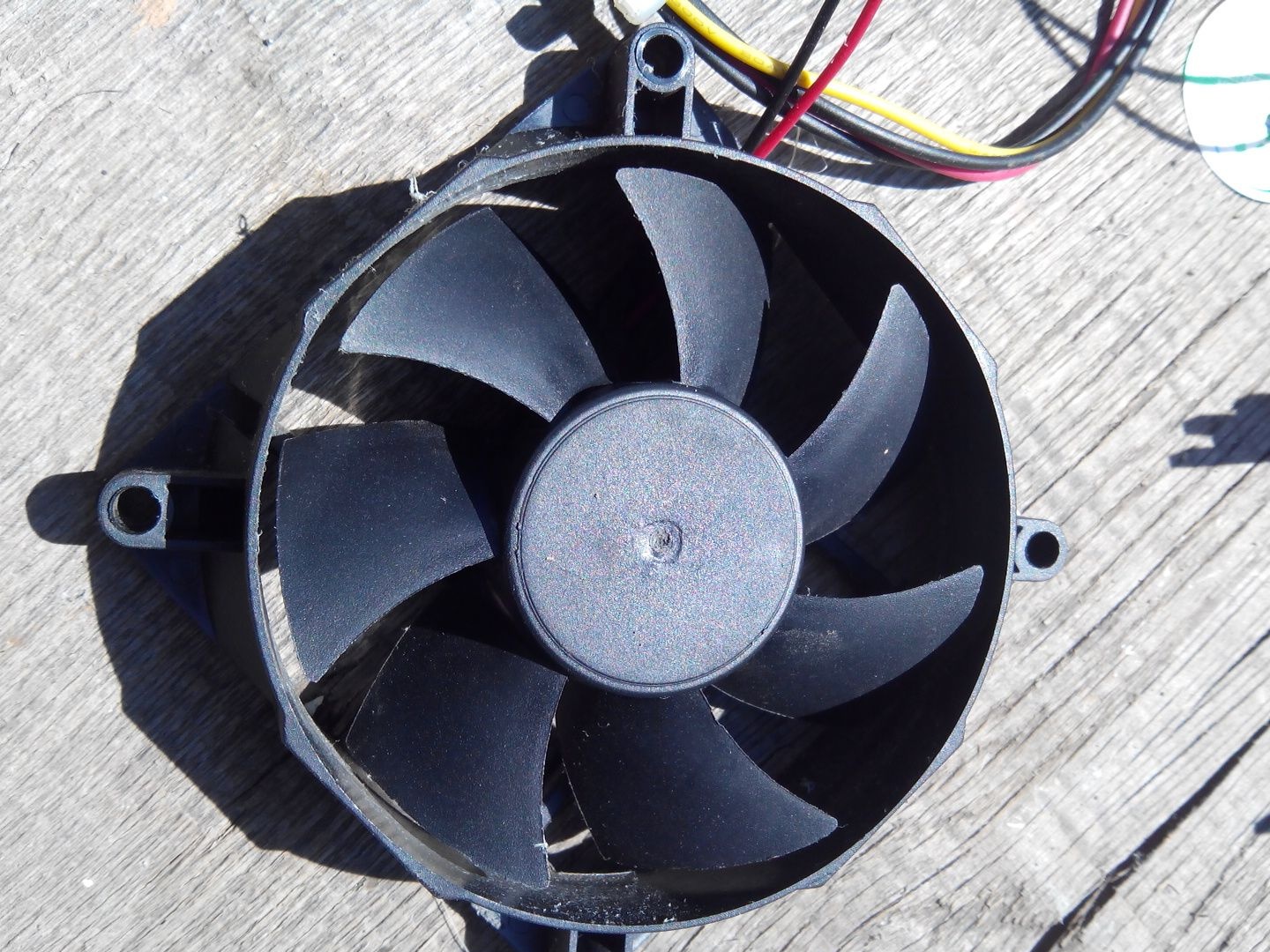
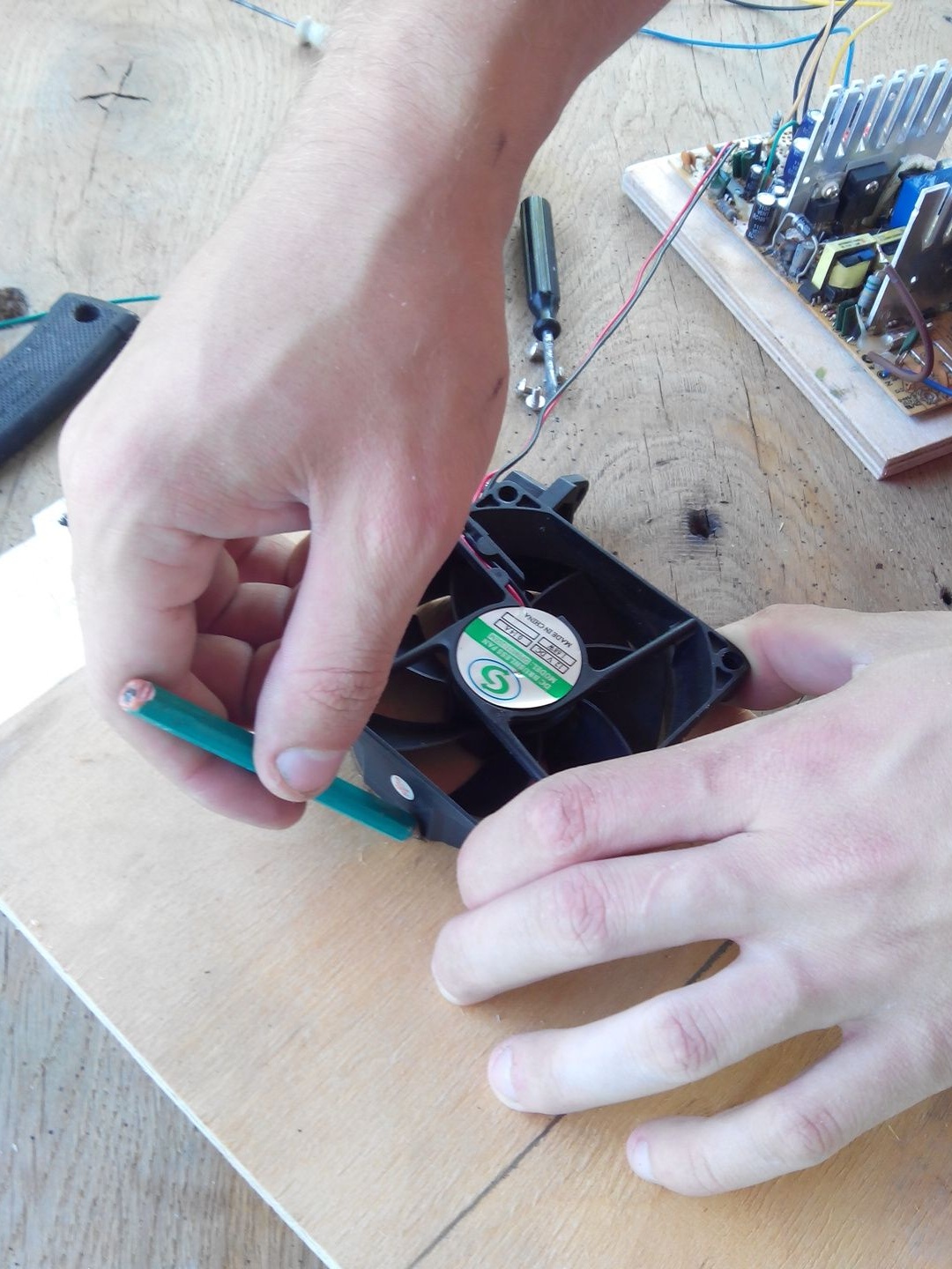
And now we’ll clean everything from dust, it was not possible to clean the cooler, I took it apart and greased it properly.
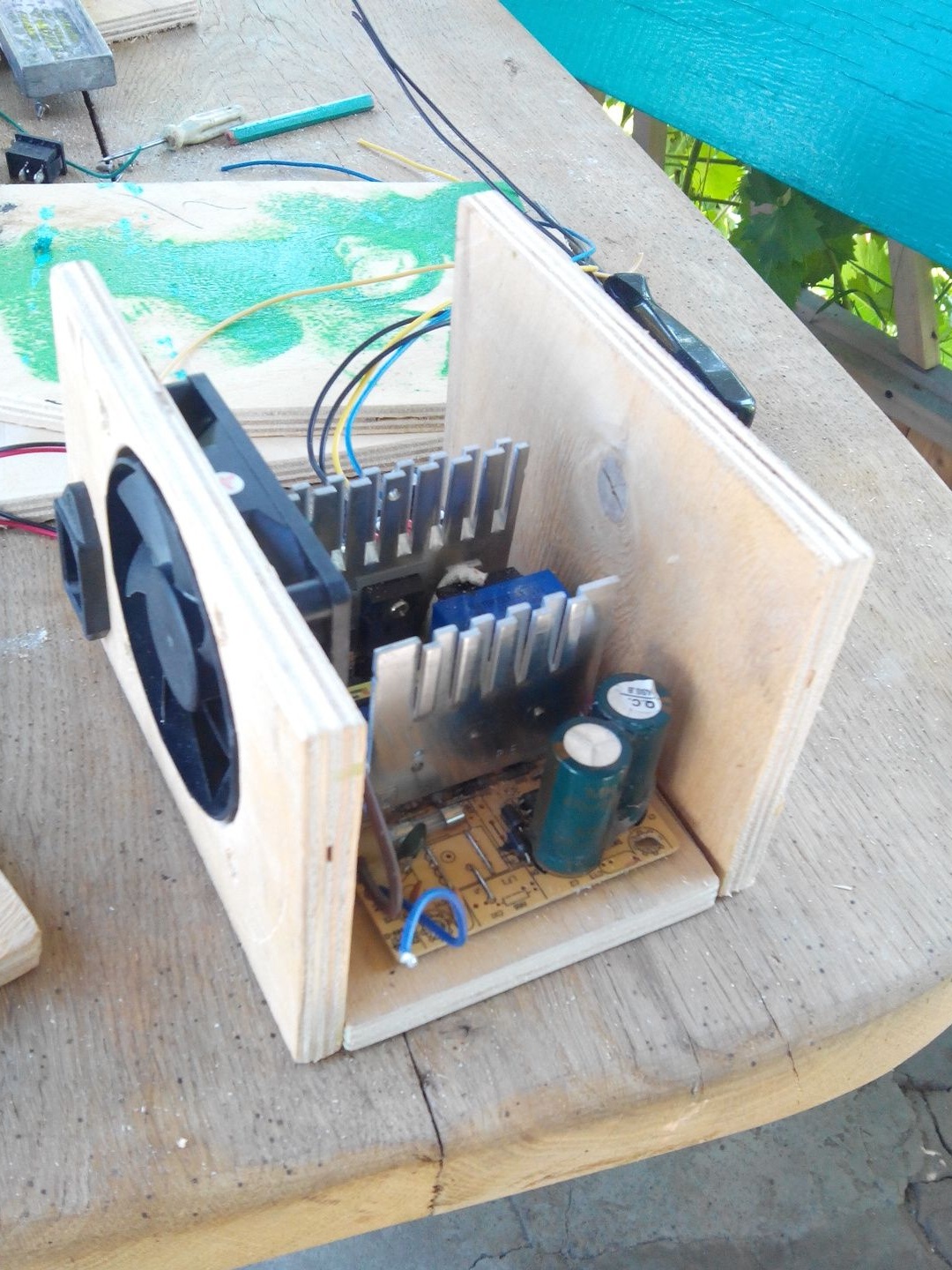
Everything is now clean and you can already proceed to the manufacture of the case.
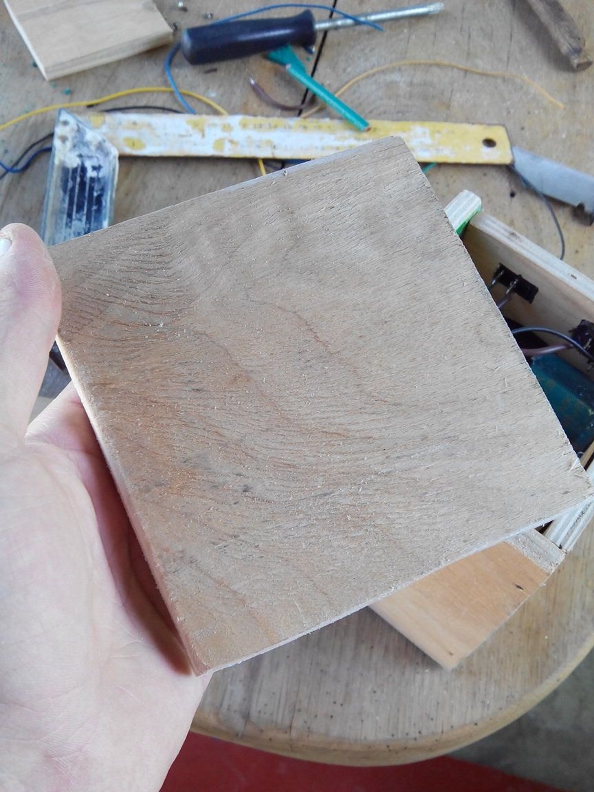
Armed with a jigsaw, we cut out the bottom side, I made it 8 mm more on four sides than the board itself.
In the middle I made a hole for the bolt and made some money to make a thread, with the help of it and four bolts, the board will be fastened at the edges.
We fasten the board to the plywood on the central bolt.
After that we try on another piece of plywood and measure out the length and height we need. I made the height a little larger than the cooler itself, so that the power supply was not so bulky.
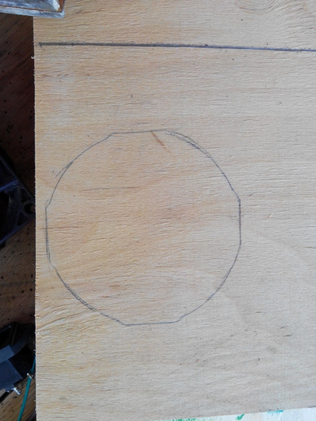
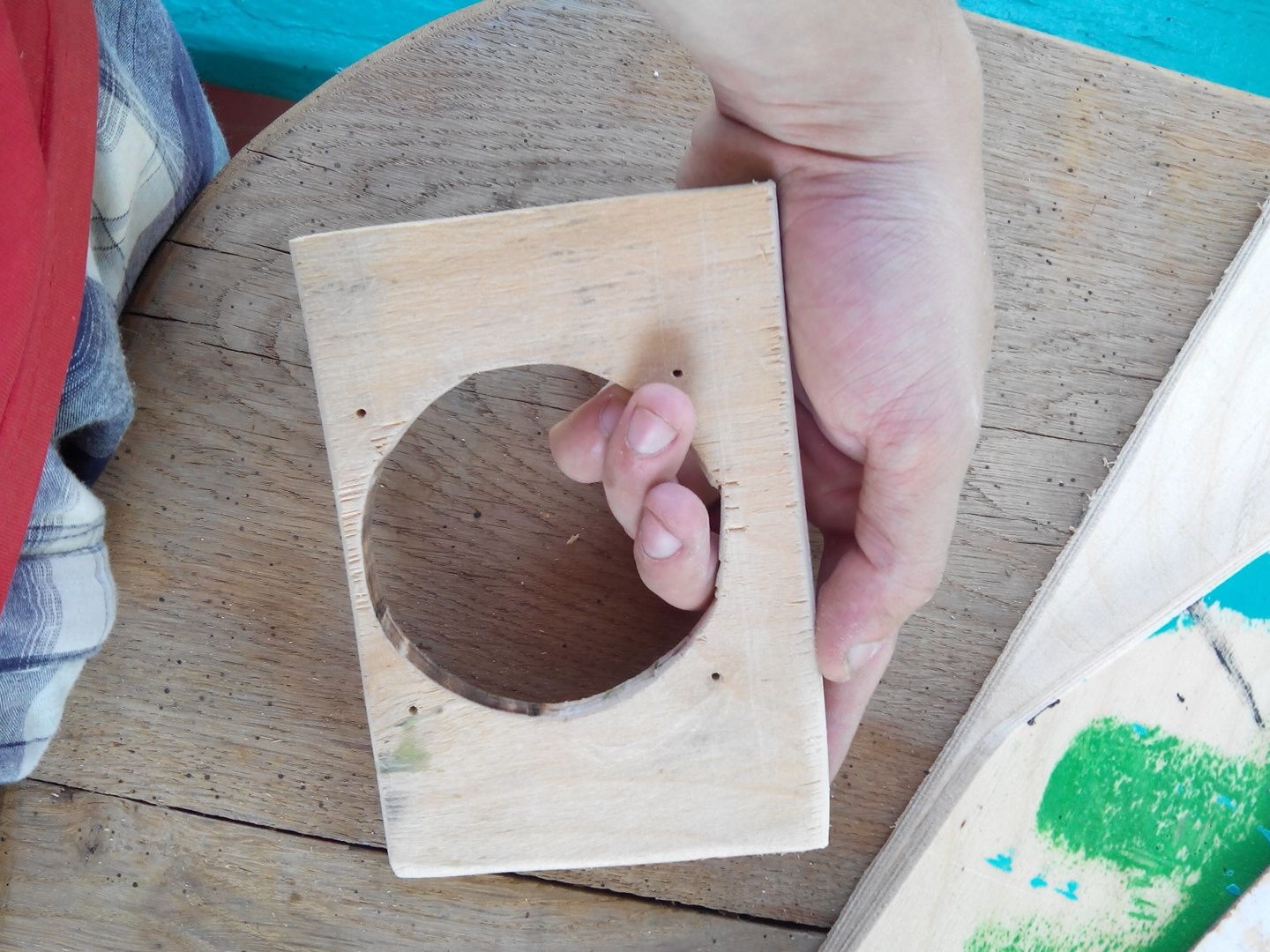
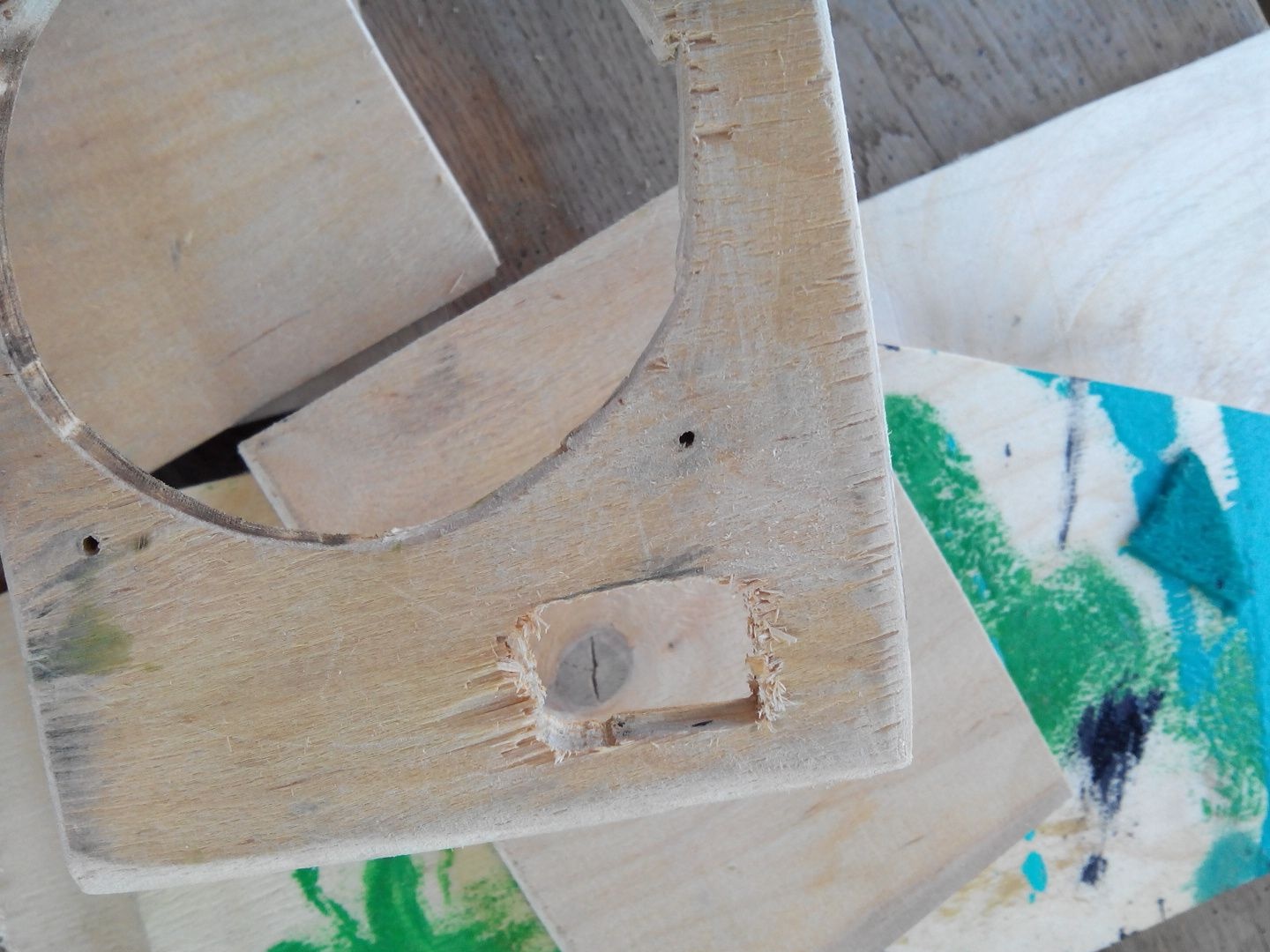
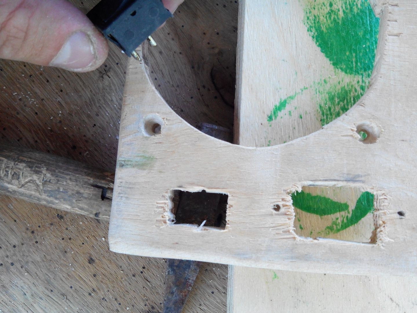
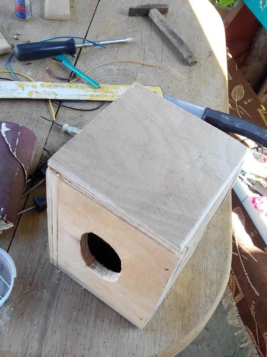
Before sawing off the front part, we mark a place on it under our cooler, it will be right in the center.
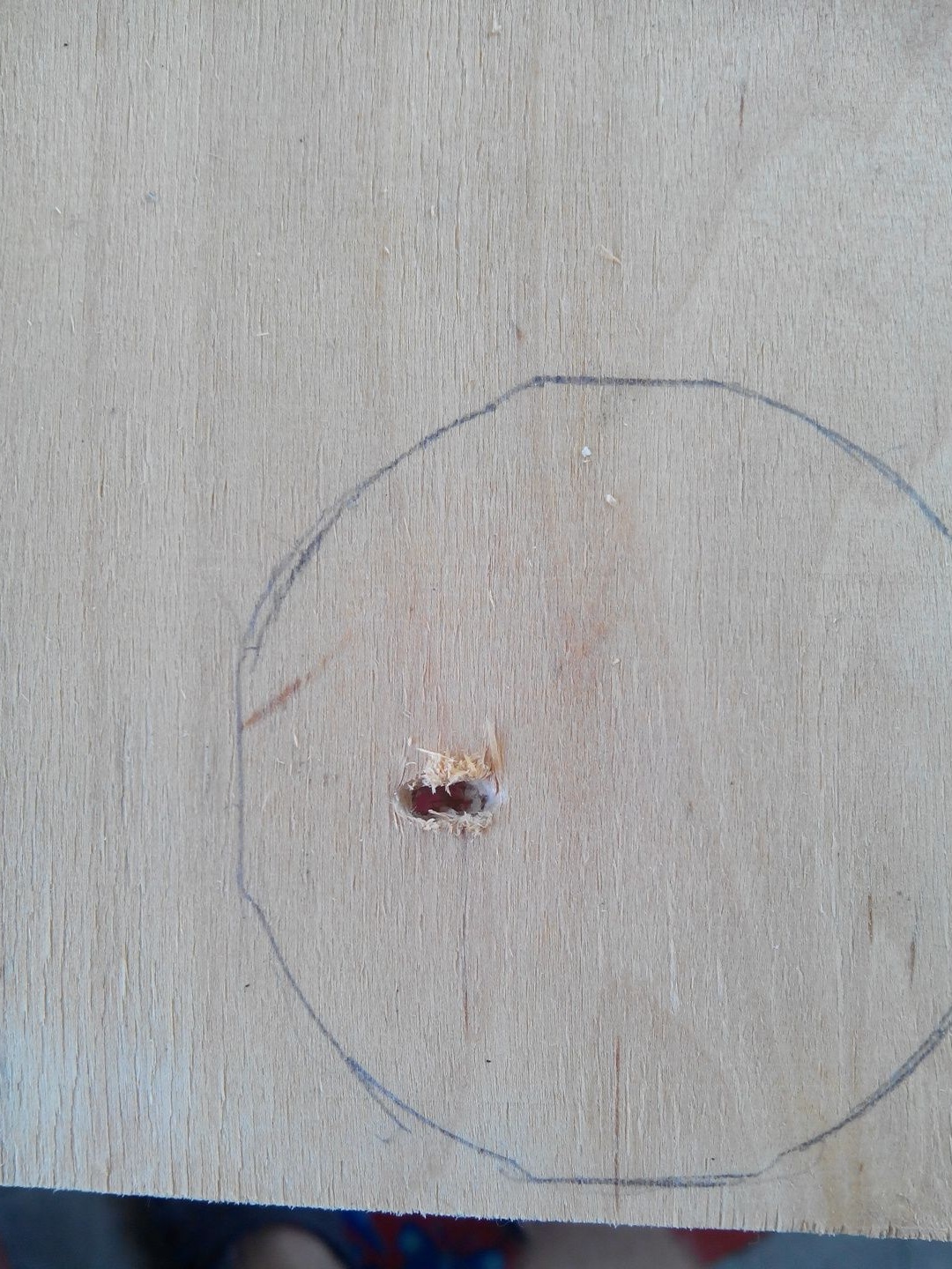
We circle with a pencil and drill two holes, make a distance between them of about 2 mm, then loosen the hole thereby removing the partition to start the jigsaw file.
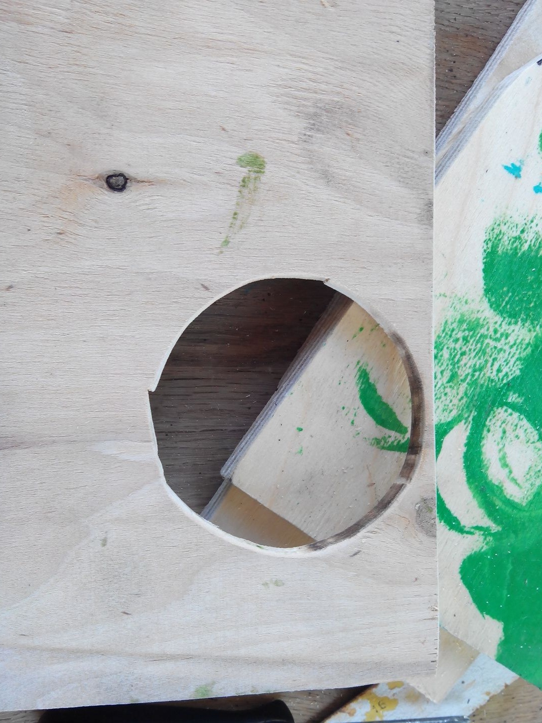
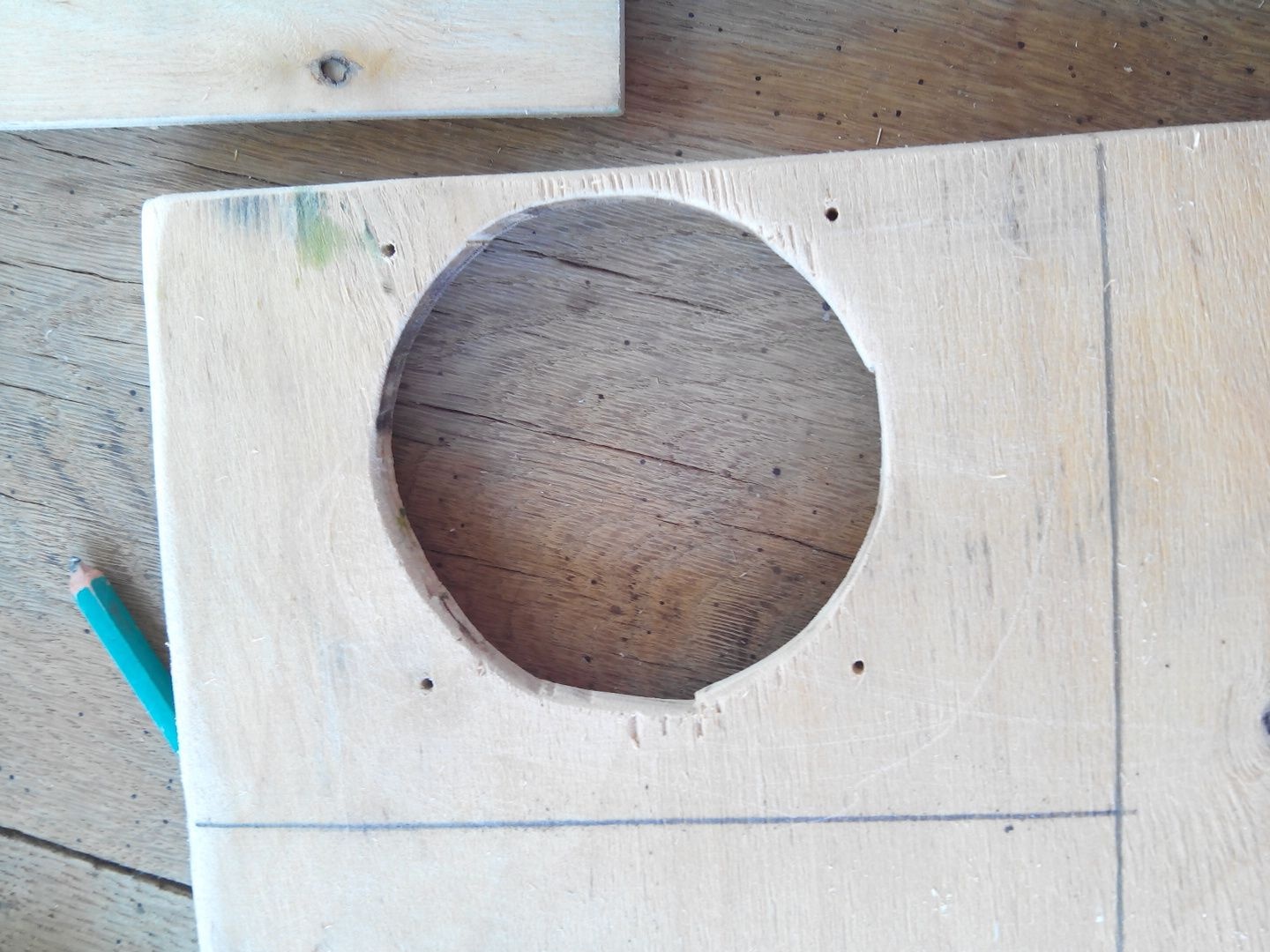
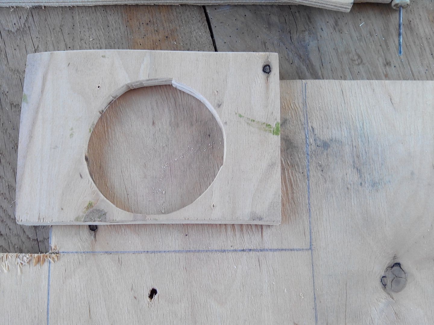
Grind the cooler seat.
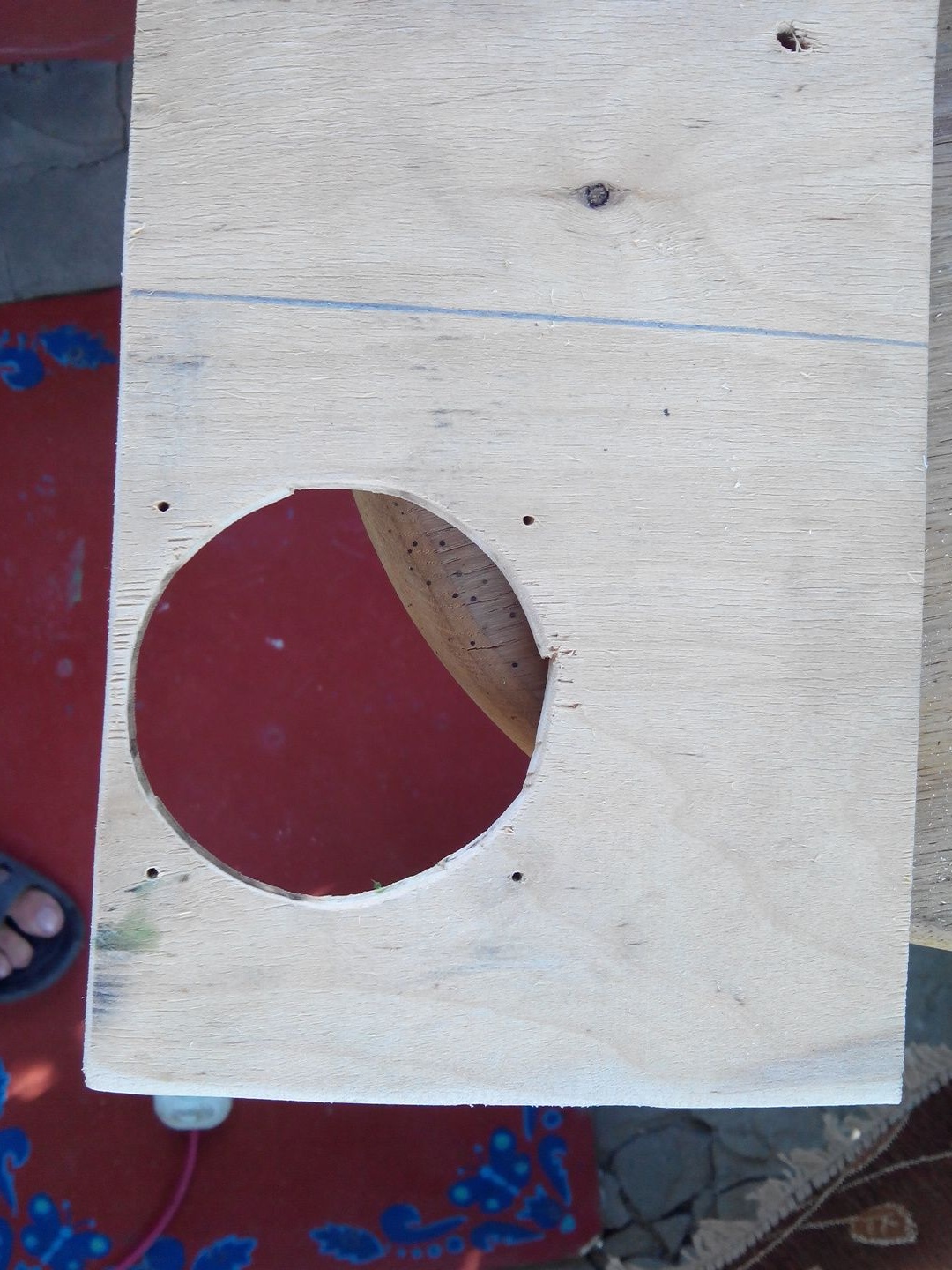
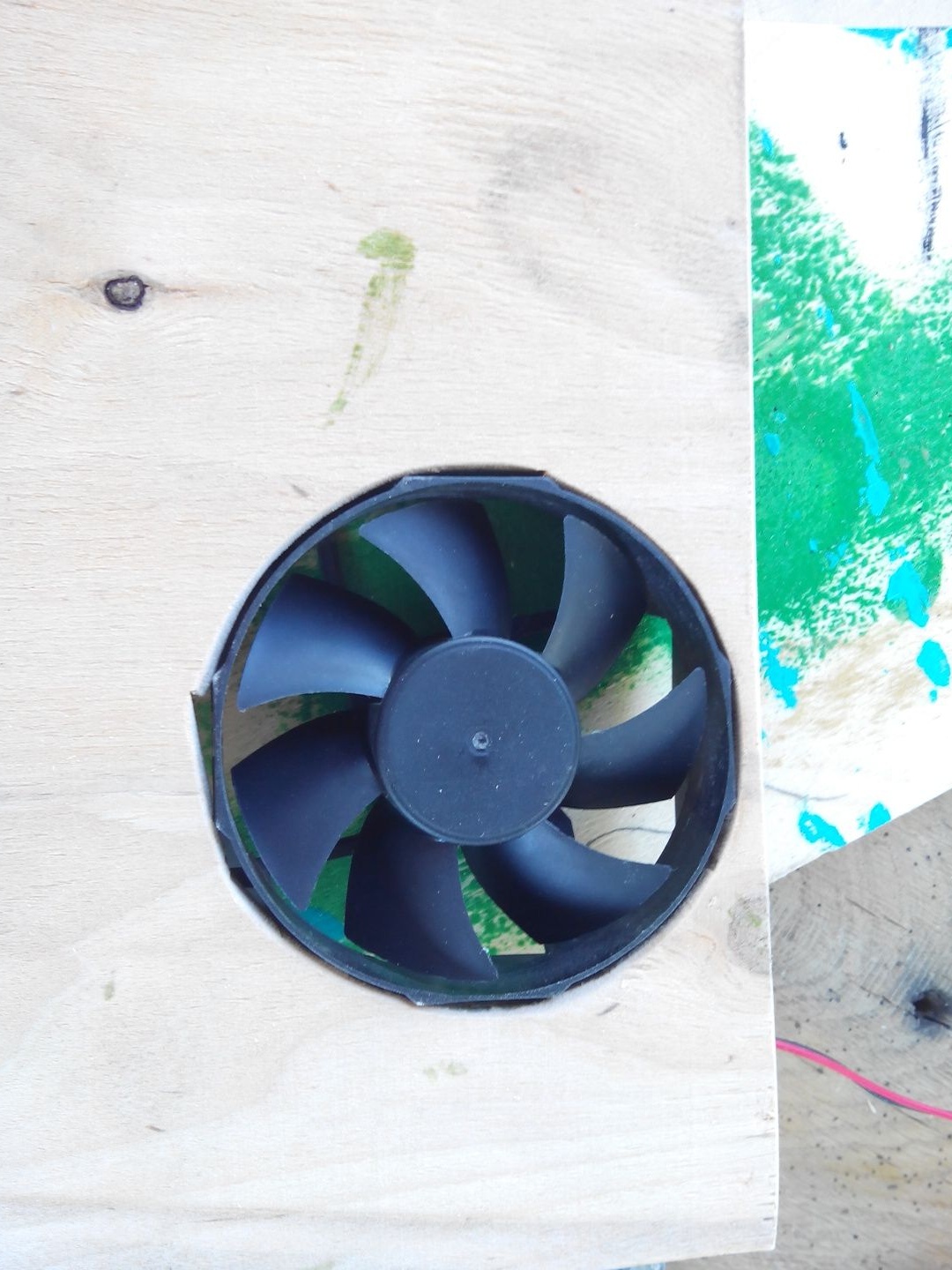
We try on, he sits there well).
With a small drill we make four holes for the bolts to fix the cooler.
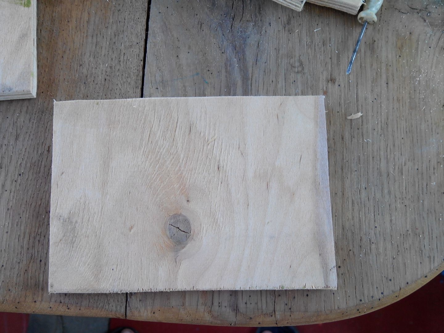
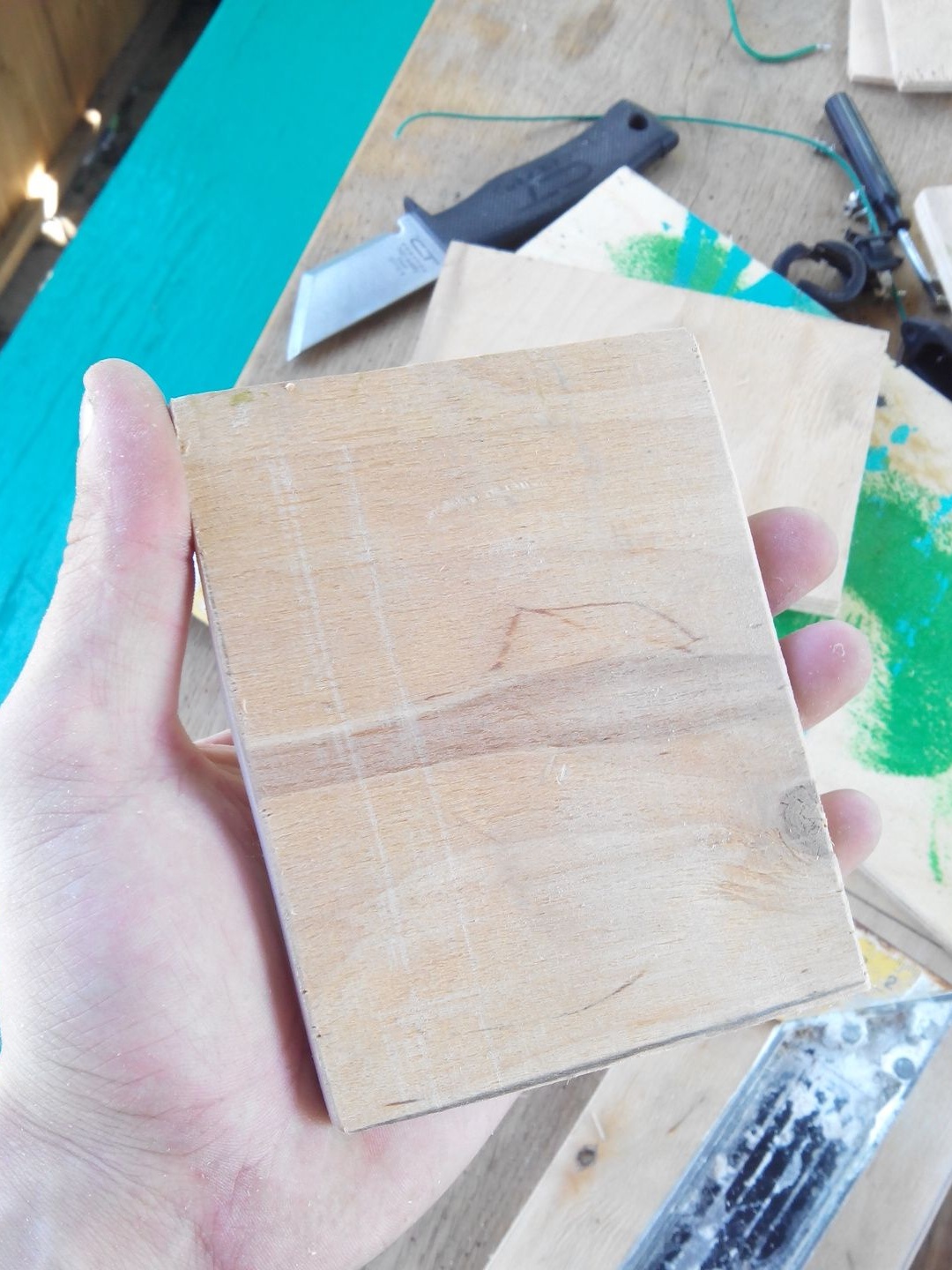
Now you can saw off the workpiece in the front.
The front, so to speak, the most important part of the block is ready, by analogy we cut out the back wall.
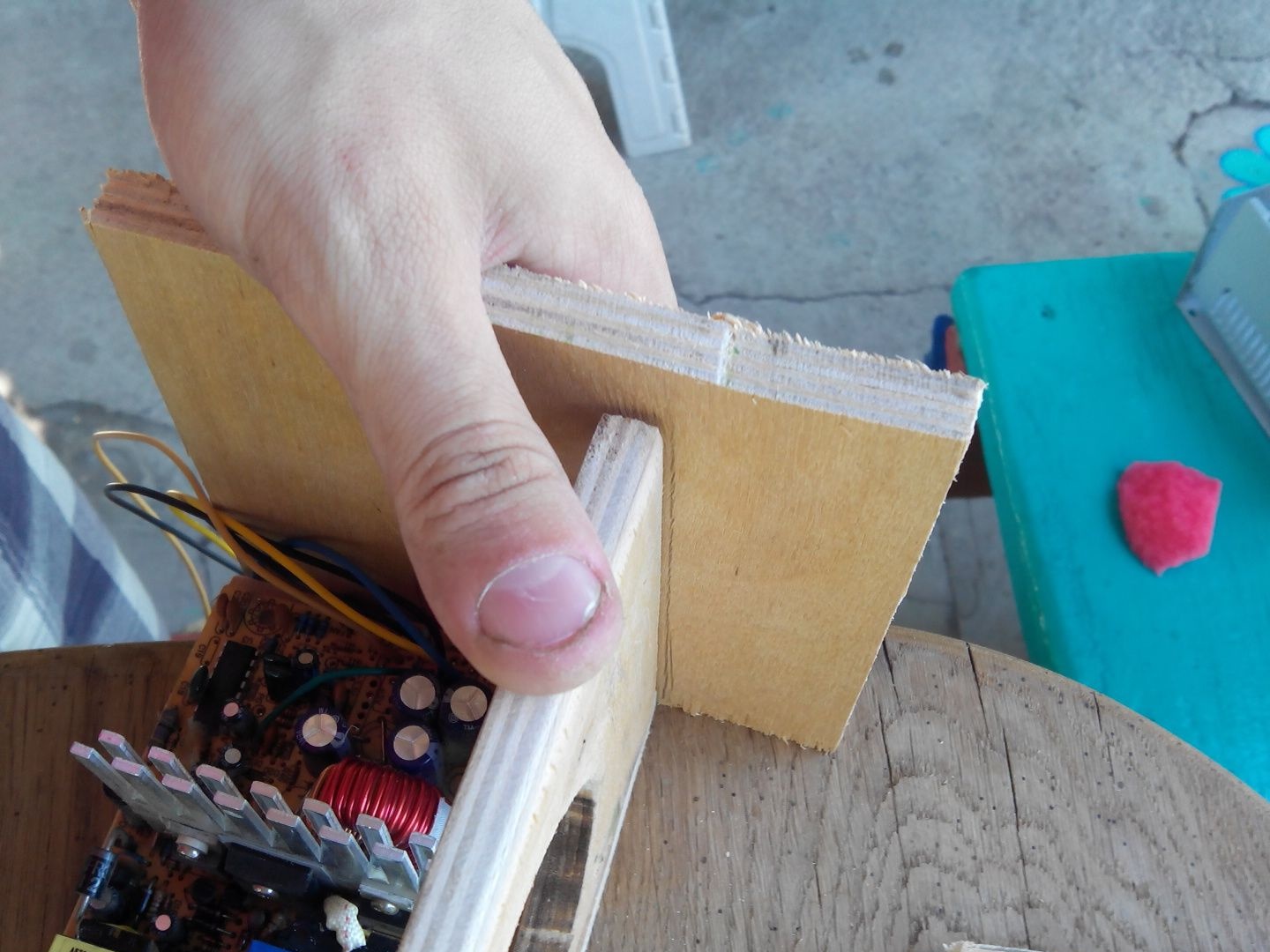
We try on the walls, it looks good, it's up to the side covers.
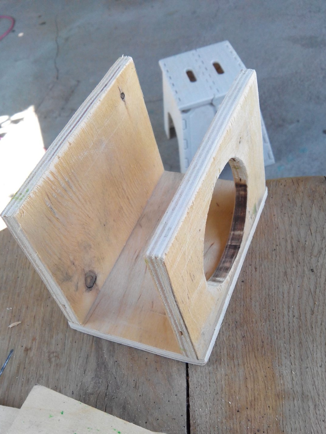
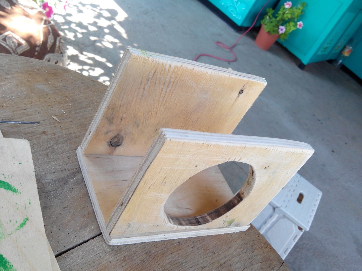
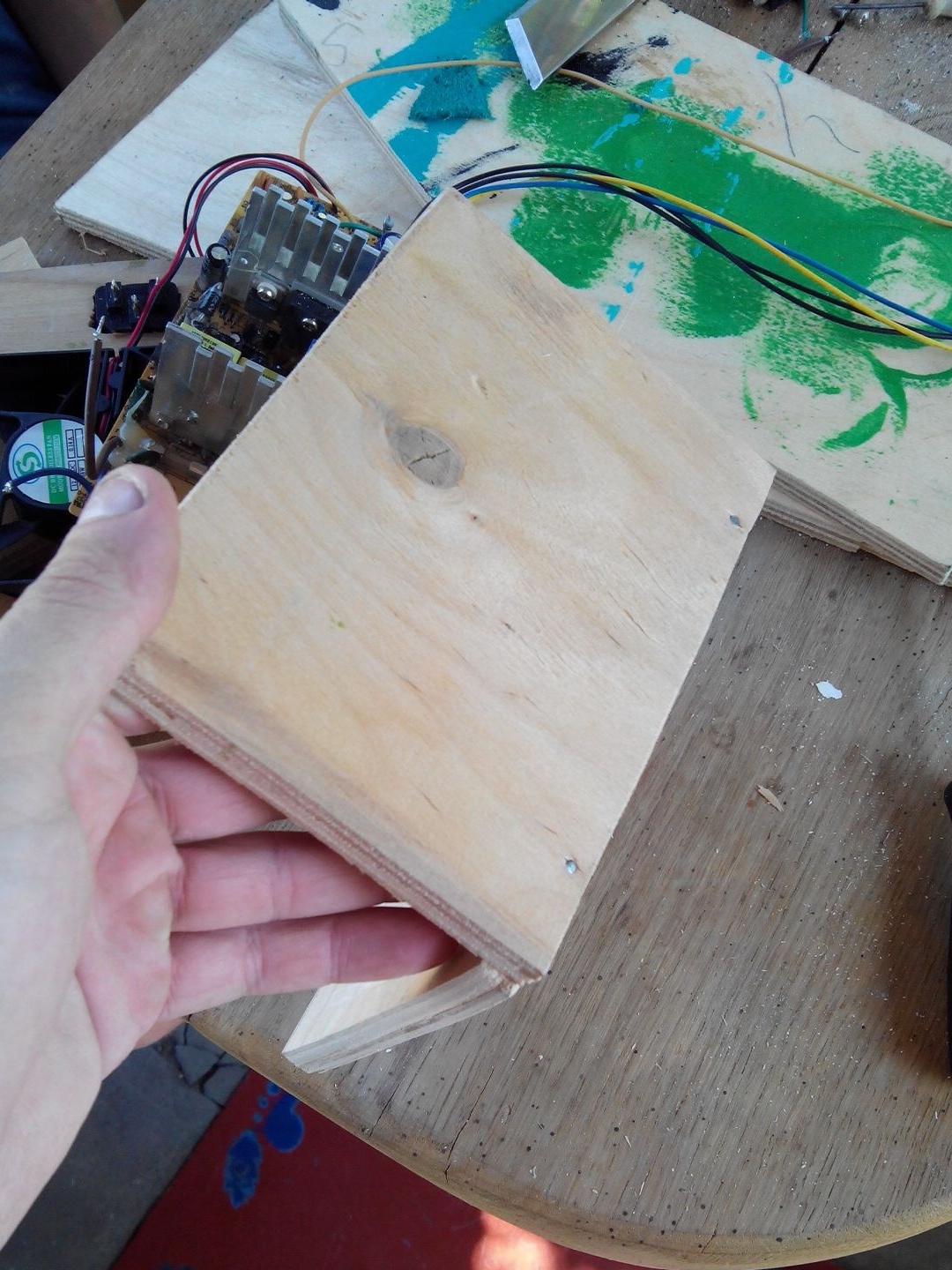
Having tried the side wall at an even angle, we outline the place for cutting with a corner.
The side wall is ready, you need another one of the same. Just circle the previous one.
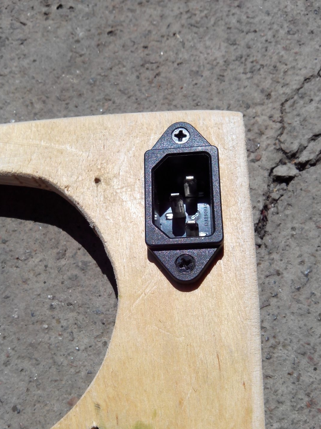
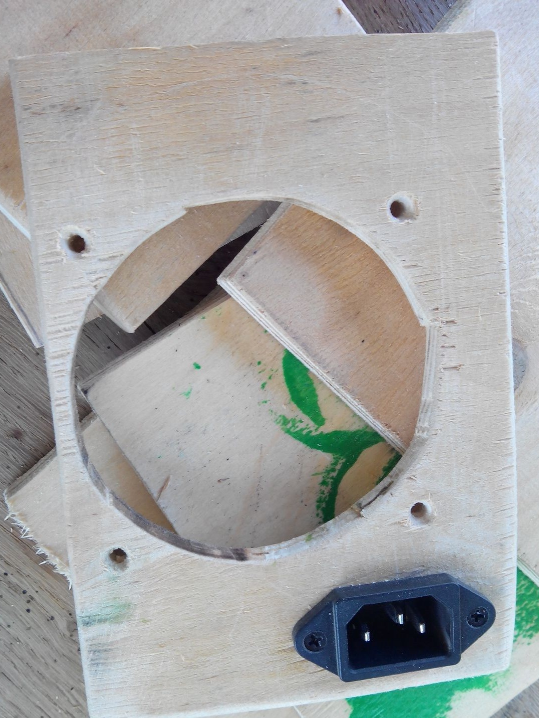
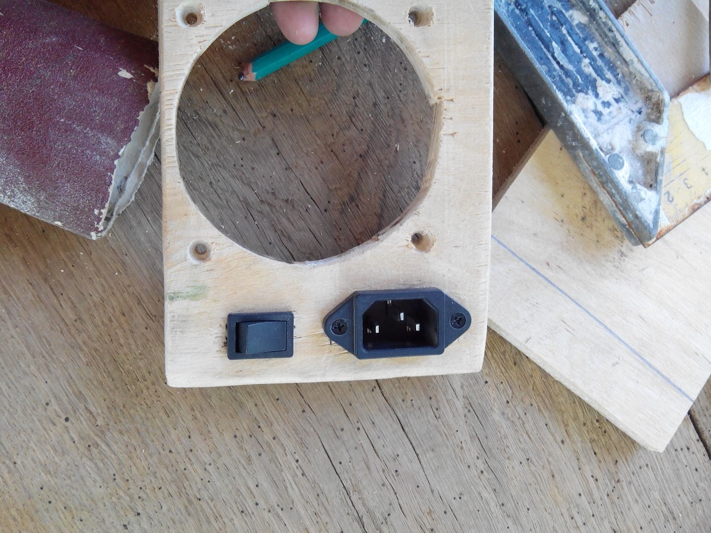
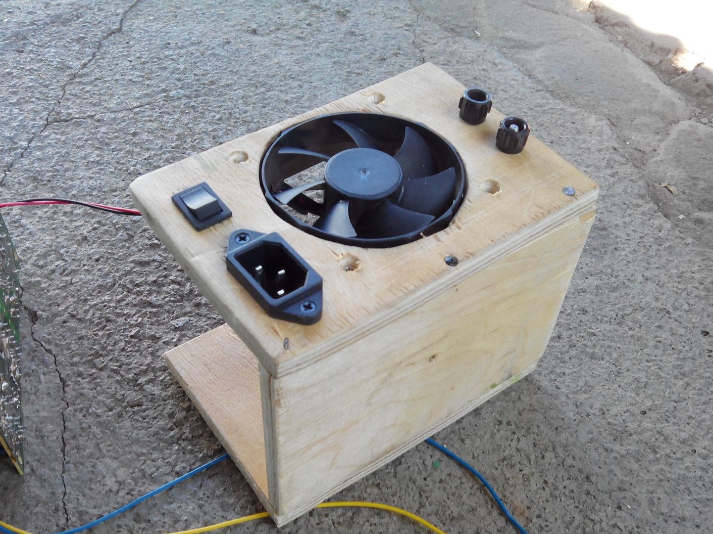
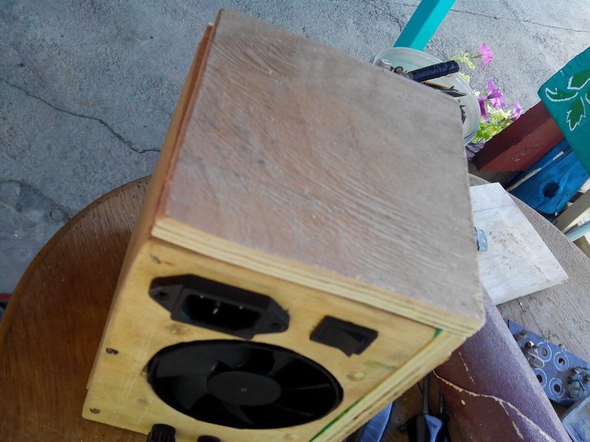
Under the 220 V cord, we make a plug, the same as in the native case, we need to place it in the front of the unit.
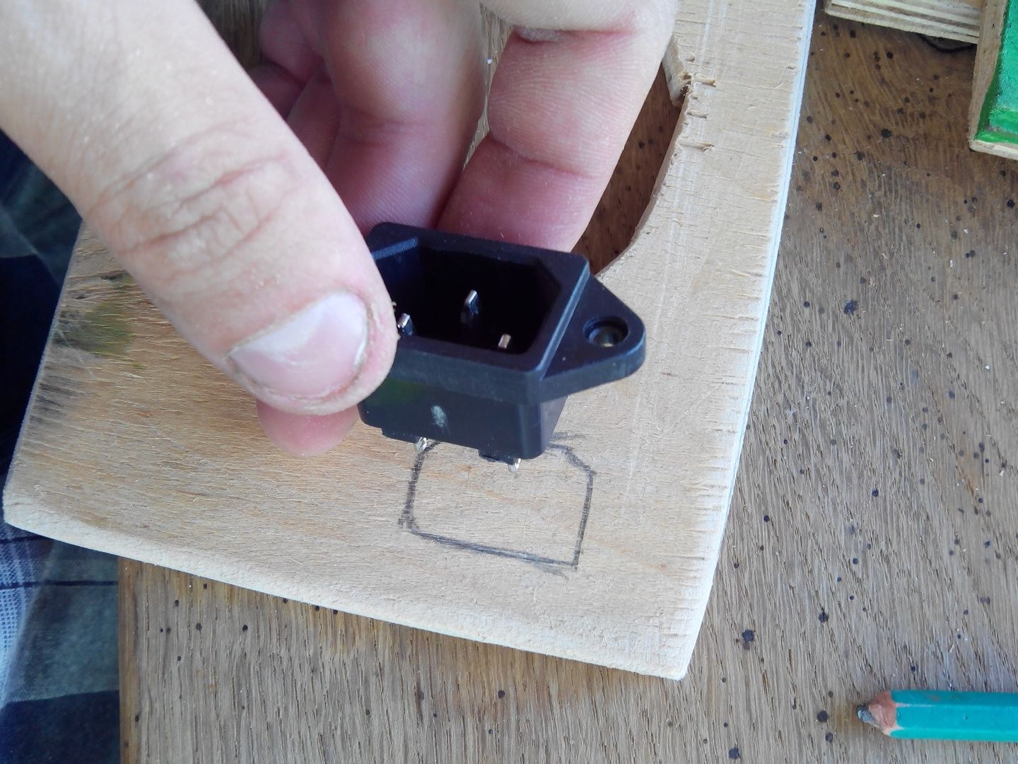
Saw it with the same jigsaw, done.
Tighten the plug-plug with two standard bolts.
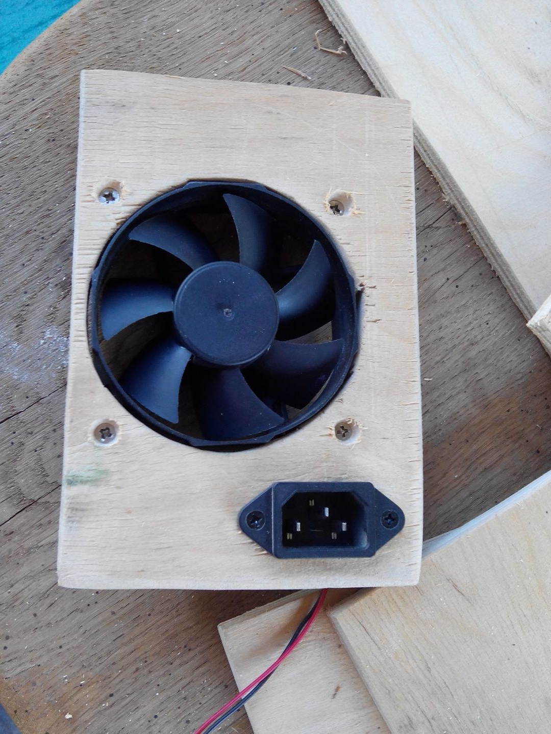
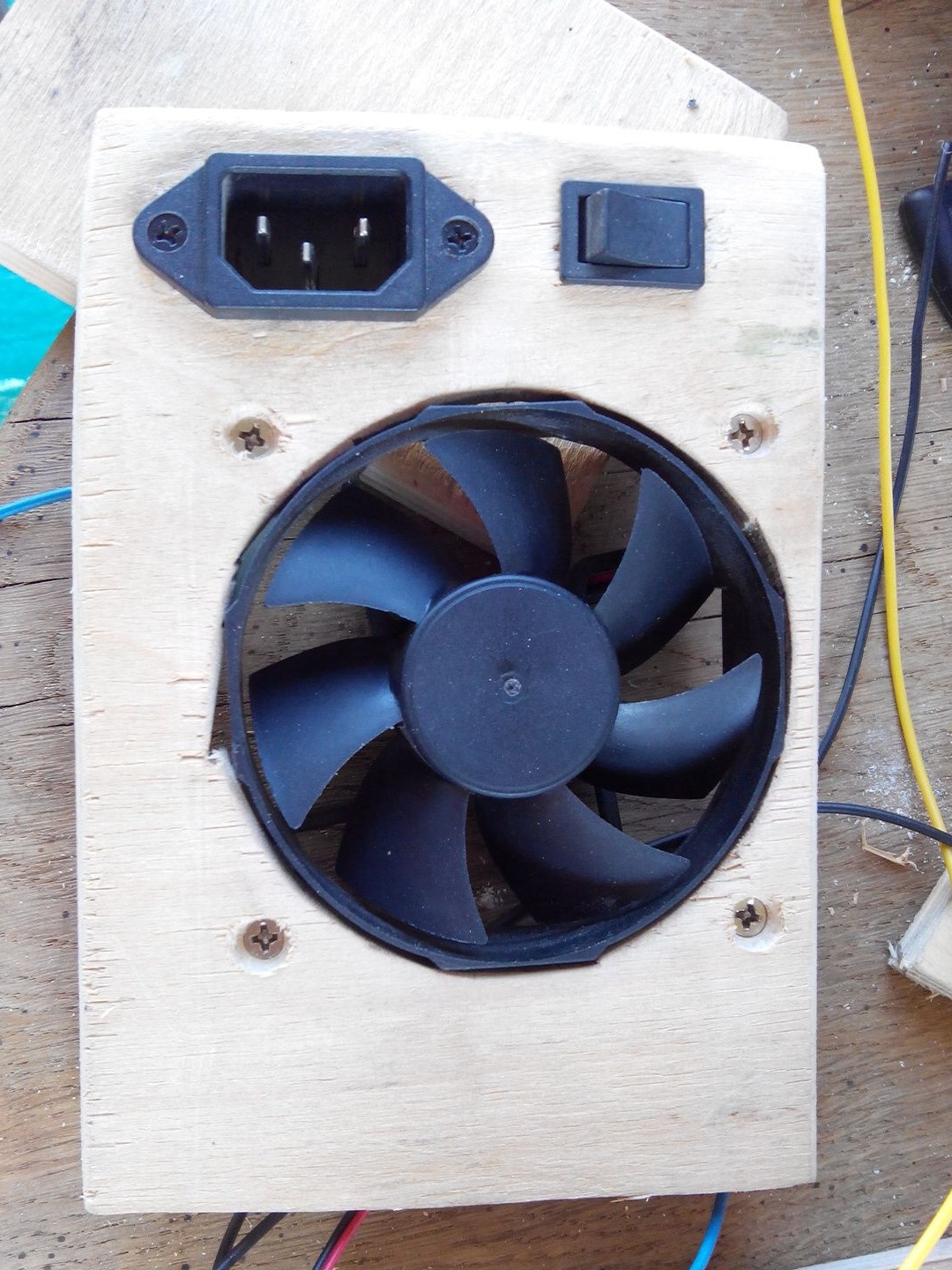
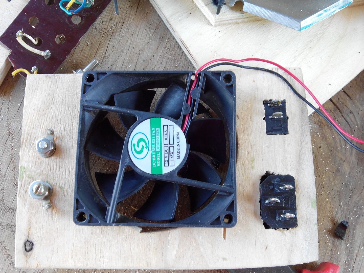
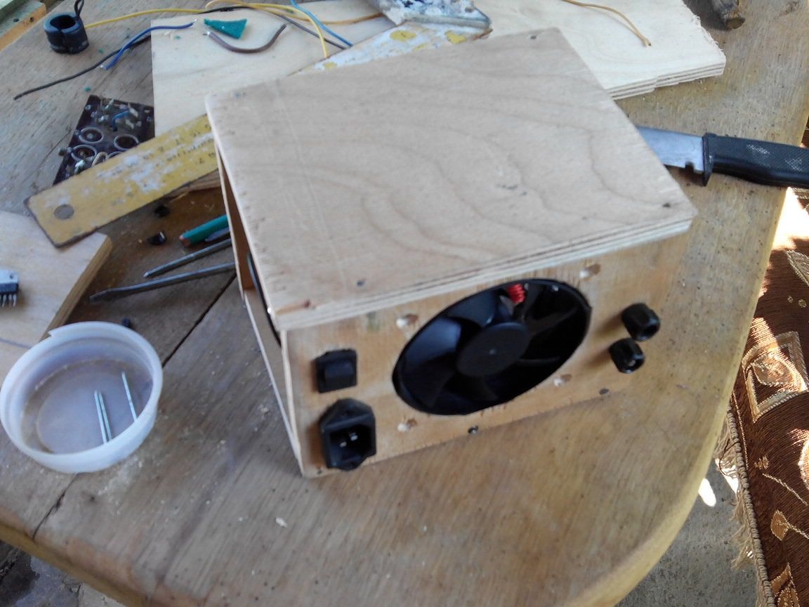
After making deep holes in the front panel under the bolts, we fasten the cooler.
Let's see how it all looks, it seems to look good, of course I'm not a designer).
We nail the lower and front sides of our block into two nails with a small hat.
Since our unit will turn on and off, it also needs a switch, I placed it next to the plug for the plug.
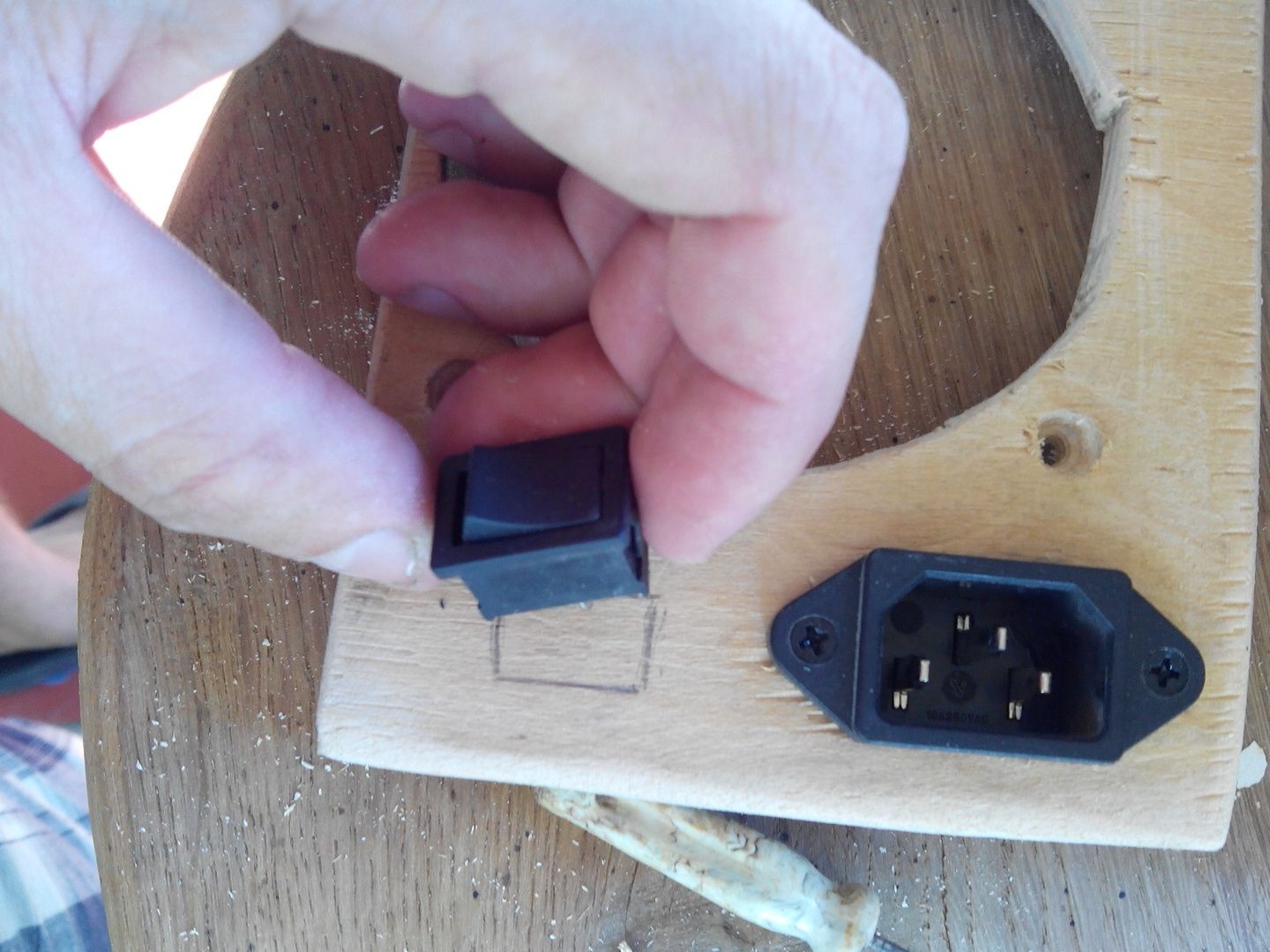
We make a place for the switch, the main thing here is not to overdo it, then it will just hang out, which is not very good.
The switch sat tight and does not play.
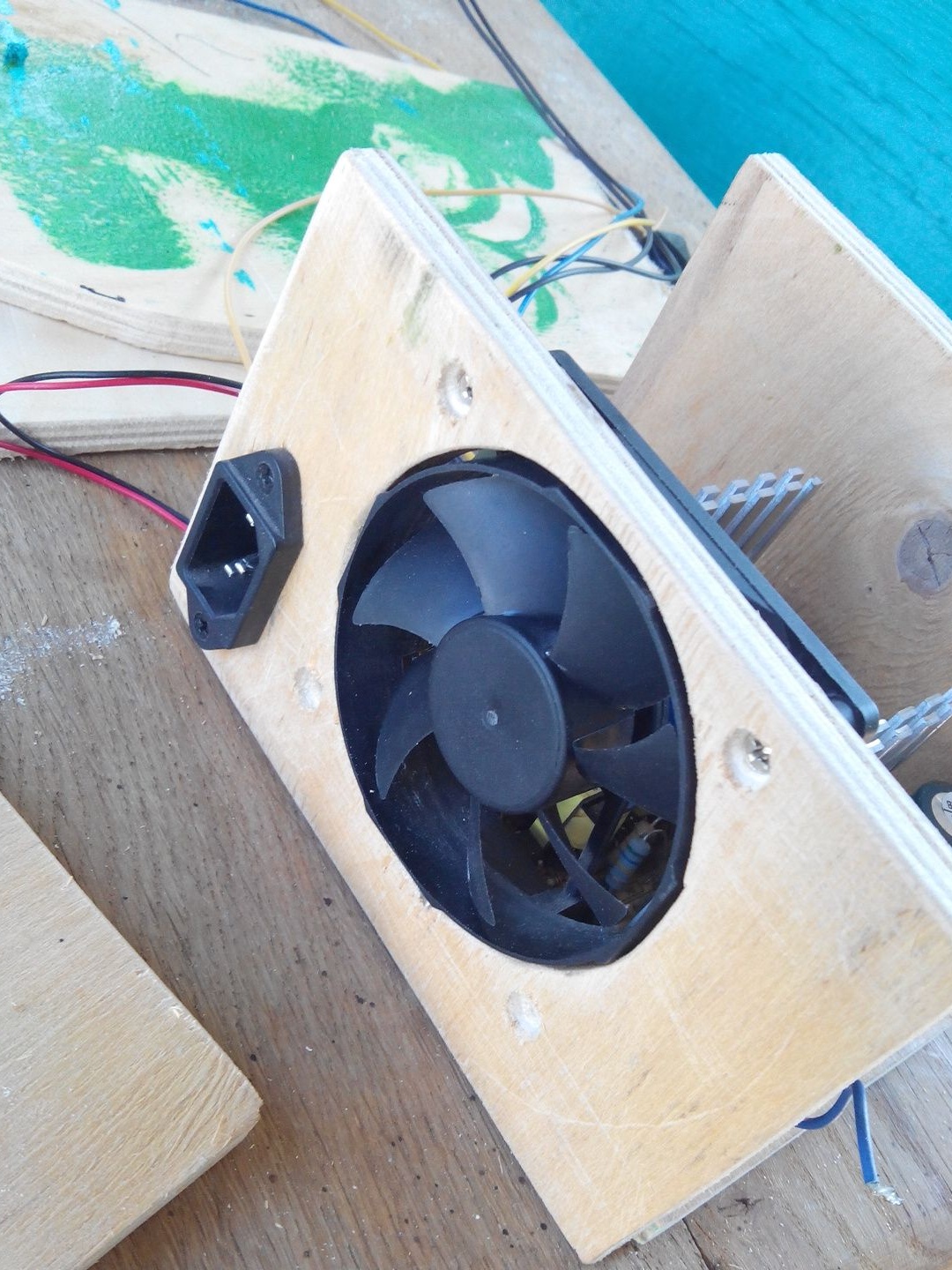
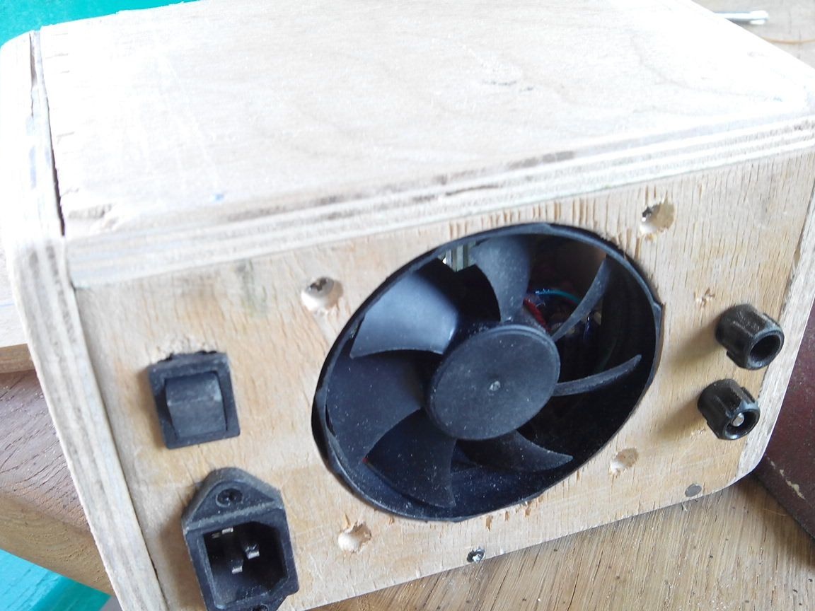
With the cooler installed, the front panel looks like this.
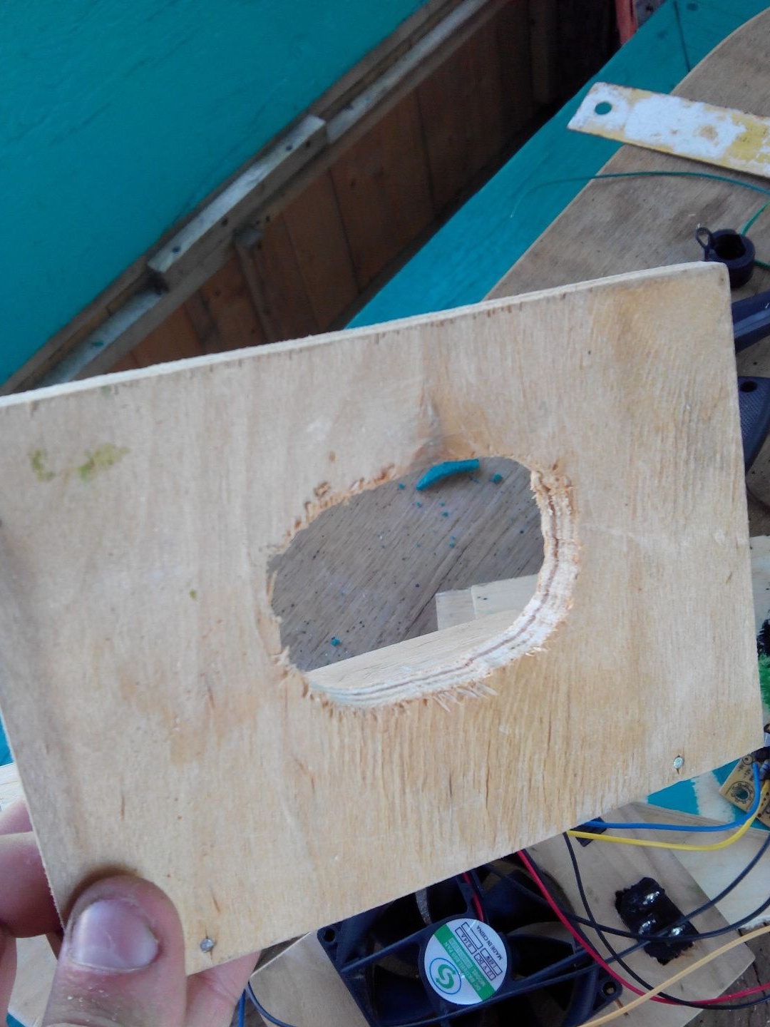
Since the back panel must have a ventilation outlet, we make an oval blow using a jigsaw.
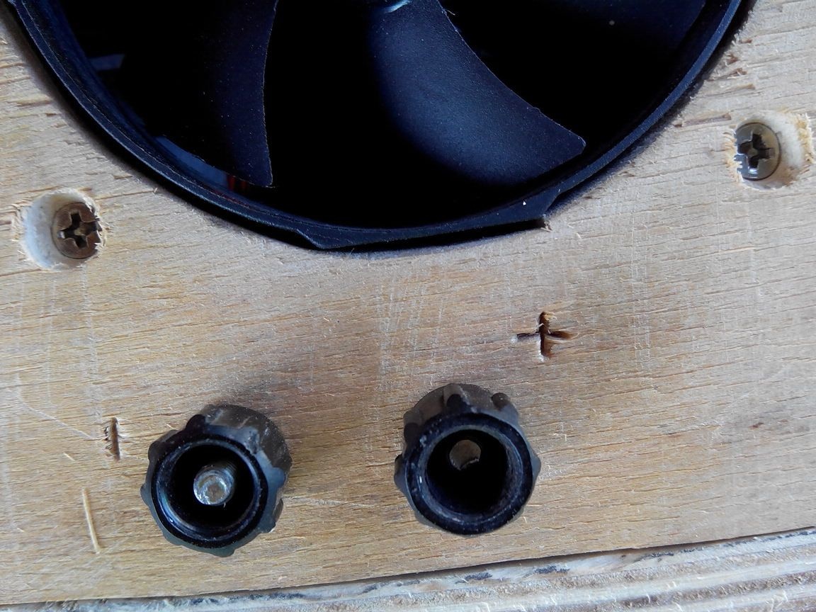
To connect the various devices that will be used with this unit, terminal blocks are needed, I found them from a school resistor.
On the reverse side everything is tightened with a nut and a plate with tinned contact is pressed with its help.
It took two of these terminal blocks, one goes to plus power, the other to minus.
And it looks like the front panel from the outside.
Having put the back panel, we nail it to the back with the front panel already fixed.
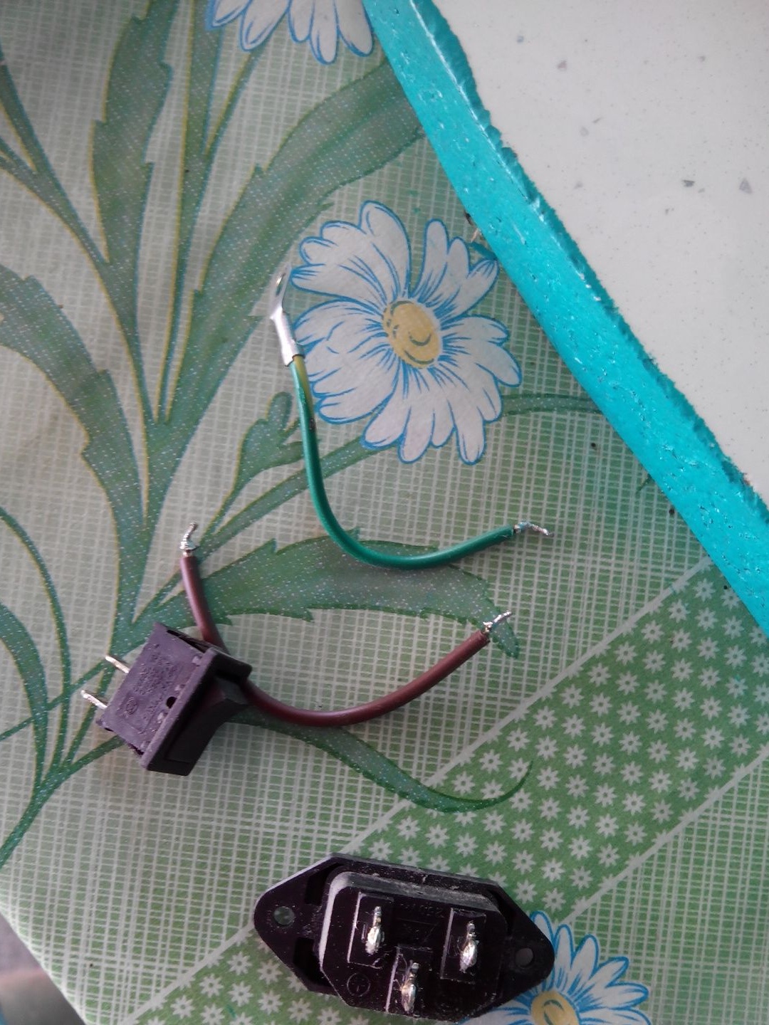
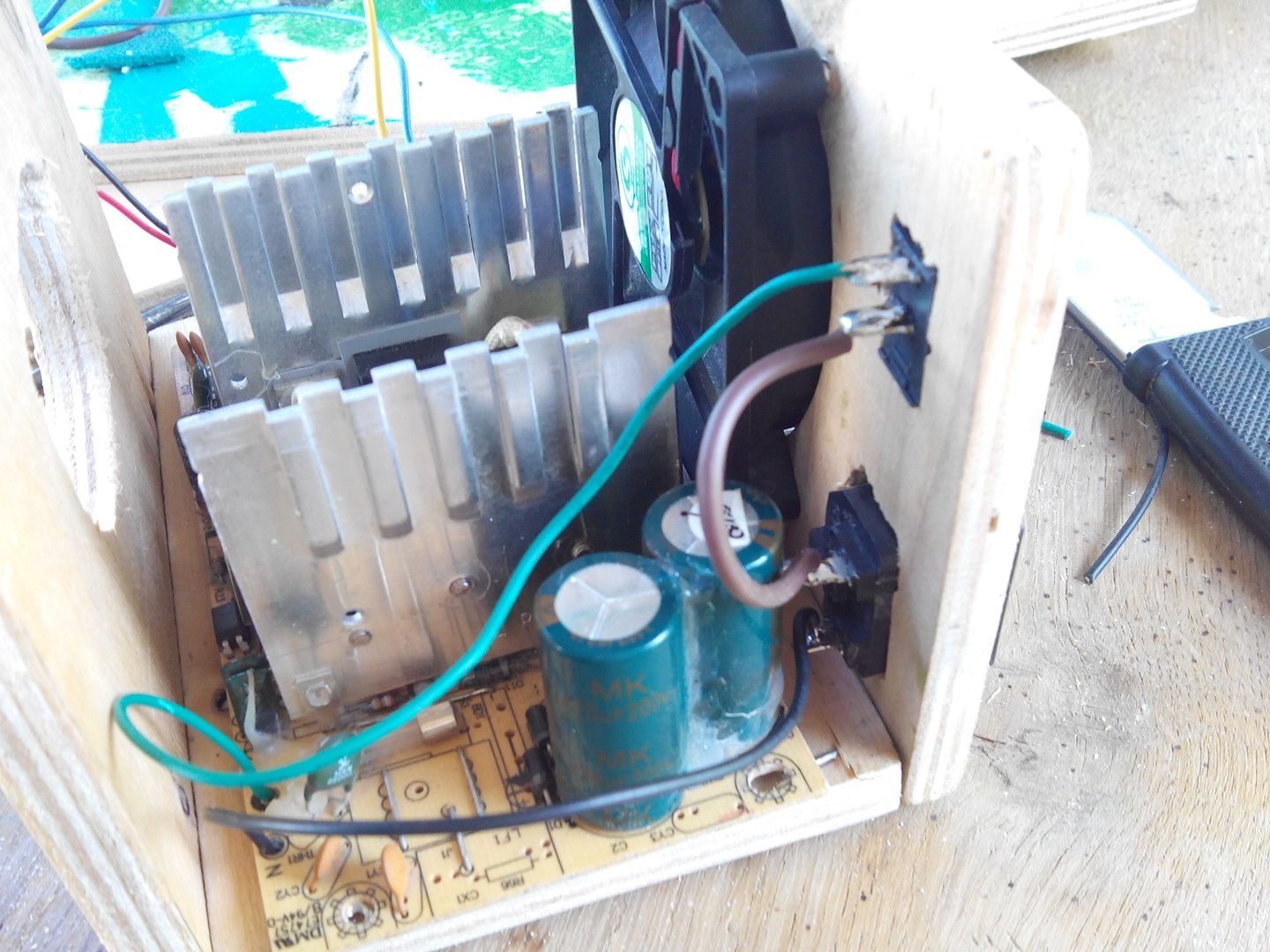
Since initially I did not think that the 220 V connection wires in my native case were short, so I had to replace them with longer ones along the way.
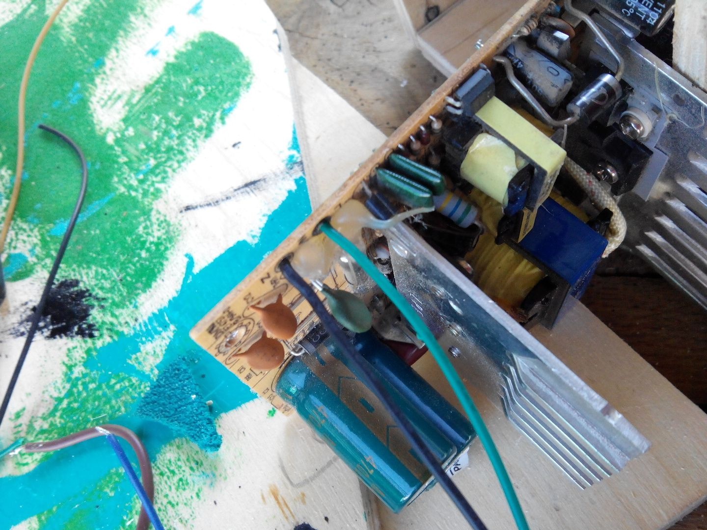
I soldered one wire to the plug, and the other through the switch.
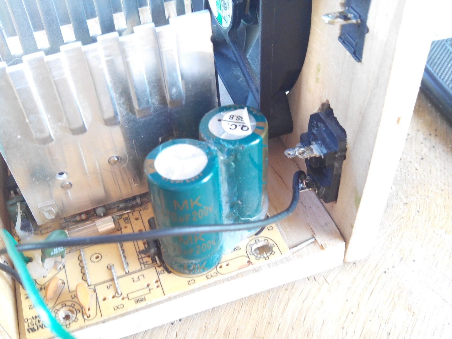
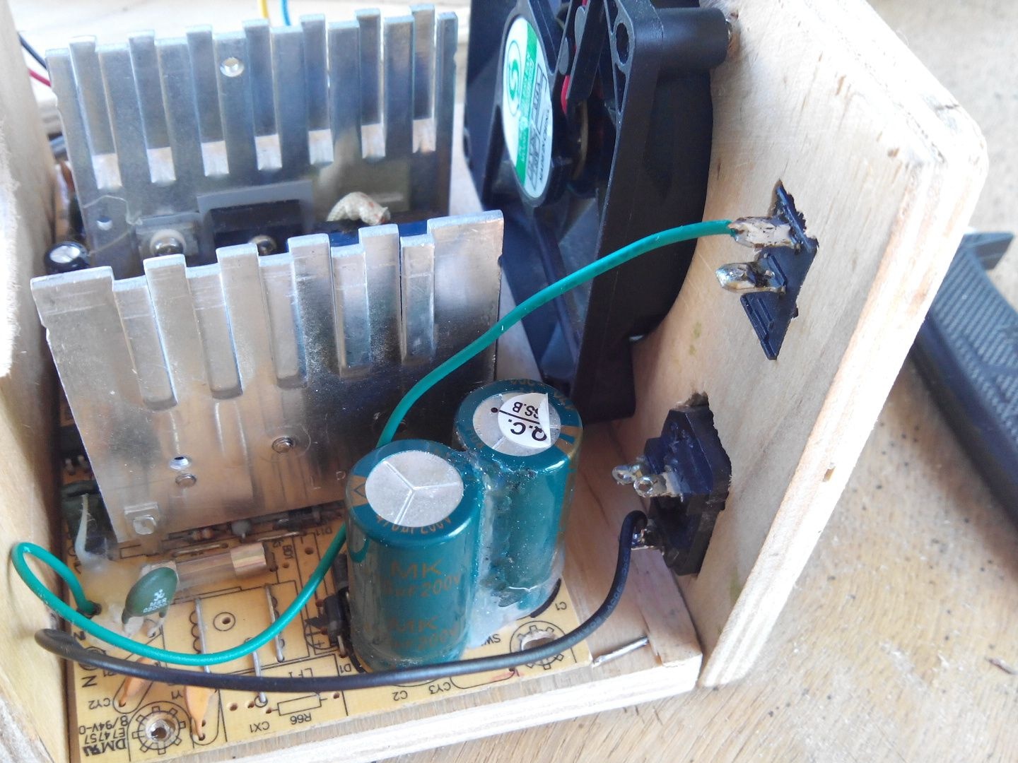
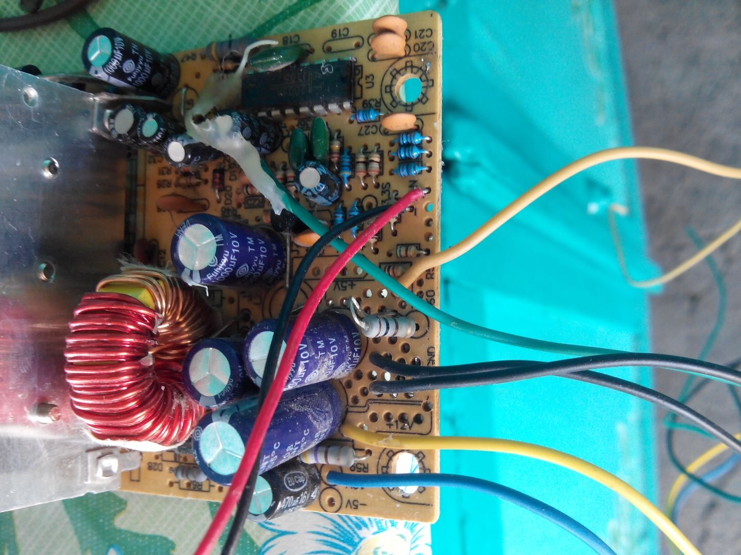
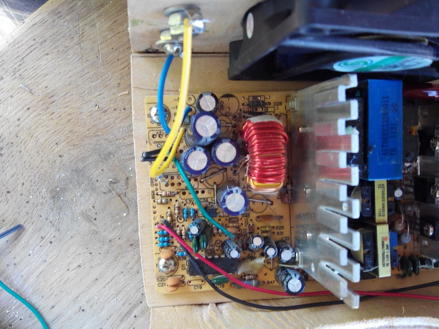
The power supply was marked that the blue wire is minus 12 volt lines, and the yellow wire is plus the same line.
Plus, I soldered higher, minus is located on the bottom.
We fasten the board to four bolts.
The front panel is now equipped with electronics, so it remains only to make the top and secure the sides.
By analogy with the bottom, we also cut the top cover. We fix it on four nails along the edges.
We hammer in two side covers, also for 4 nails.
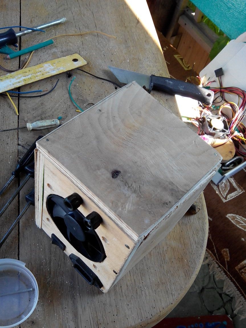
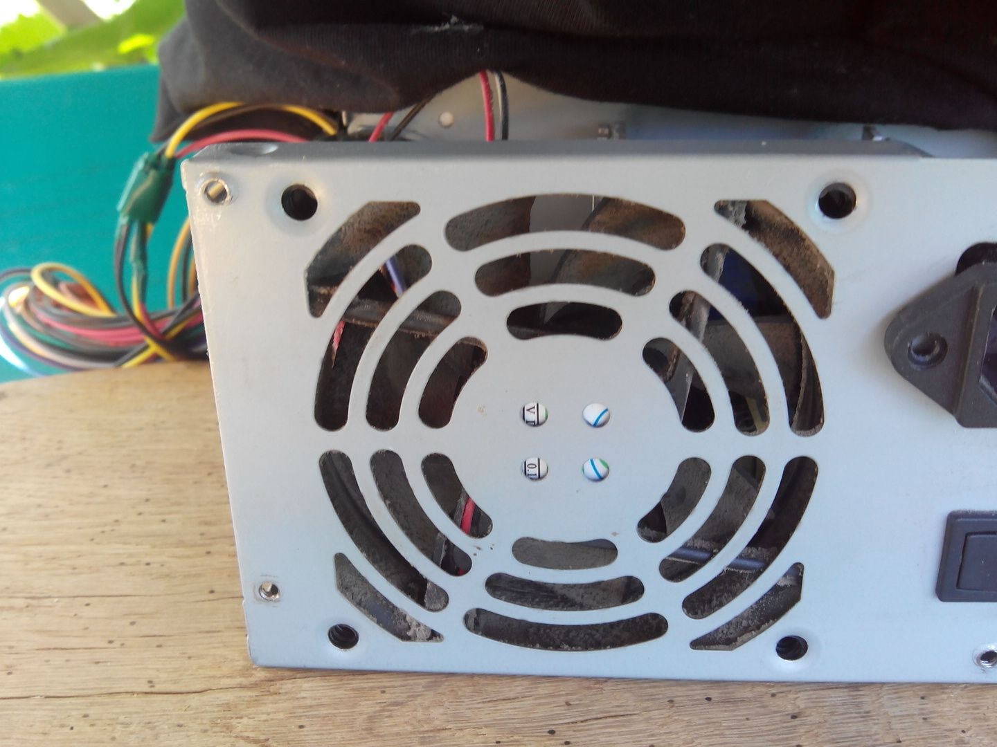
In order not to make a mistake with the polarity when connecting, I made clarifying icons with a screwdriver, plus and minus, now certainly without errors.
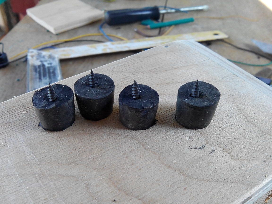
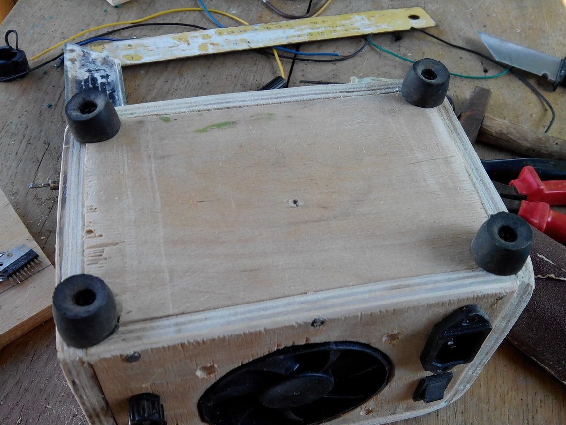
In conclusion, I added 4 legs to the bottom side, made of corks for chemical tubes, I sawed them in half, as they were high and tightened it with 4 screws, one for each leg.
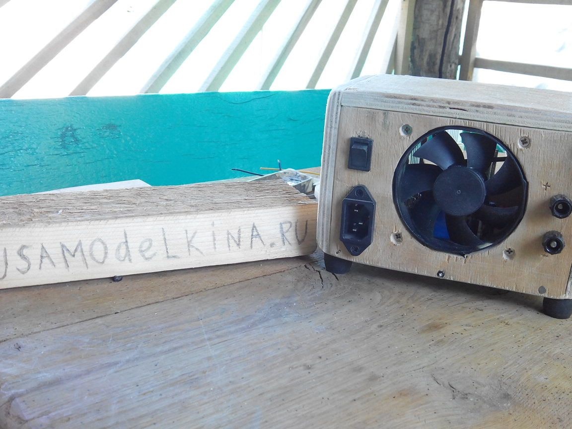
On this, the laboratory power supply is ready, with its help you can listen to the car radio, check for light bulbs, power the car amplifier.
All successful homemade and interesting ideas.