
Arduino is a microcontroller board that you can program to control external devices. It interacts with the outside world through sensors, motors, LEDs, speakers ... and even the Internet, which makes it a flexible platform for various projects. There are quite a few microcontrollers, but Arduino is popular due to the fact that various projects are very actively laid out and discussed on the Internet. If you search on google or youtube, you will find millions of ideas and information to start exploring Arduino yourself.
Even if you don’t have experience programming microcontrollers - with Arduino you will quickly learn and learn something about electronics using experiments.
What do you need to get started?
Arduino Uno- 1pc
Usb cable-1pcs
Jumpers 1pc
1pcs development board
Red LED 4 pcs
220 ohm resistor 4pcs
Resistor 10 room 1 pc
Button without fixing
Potentiometer
RGB LED with common cathode
All this can be bought at a local radio store or ordered on the Internet.
An online simulator was used to demonstrate and simulate electrical circuits.
This simulator works best in the Chrome browser.
Let's take a closer look at the Arduino.
Arduino is not a large computer to which external circuits can connect. Arduino Uno uses Atmega 328P
This is the largest chip on the board. This chip executes programs that are stored in its memory. You can download the program via usb using the Arduino IDE. The usb port also provides power to the arduino.
There is a separate power connector. There are two outputs on the board, designated 5v and 3.3v, which are needed in order to power various devices. You will also find pins marked as GND, these are ground leads (ground is 0V). The Arduino platform also has 14 digital outputs (pins), marked with numbers from 0 to 13, which are connected to external nodes and have two states, high or low (on or off). These contacts can work as outputs or as inputs, i.e. they can either transmit some data and control external devices, or receive data from devices. The following conclusions on the board are designated A0-A5. These are analog inputs that can receive data from various sensors. This is especially convenient when you need to measure a range, such as temperature. The analog inputs have additional functions that can be activated separately.

How to use a breadboard.
A breadboard is needed to temporarily connect the parts, to check how the device works, before you solder everything together.
All of the following examples are collected on a breadboard so that you can quickly make changes to the circuit and reuse parts without bothering with soldering.
The breadboard has rows of holes in which you can insert parts and wires. Some of these holes are electrically connected to each other.
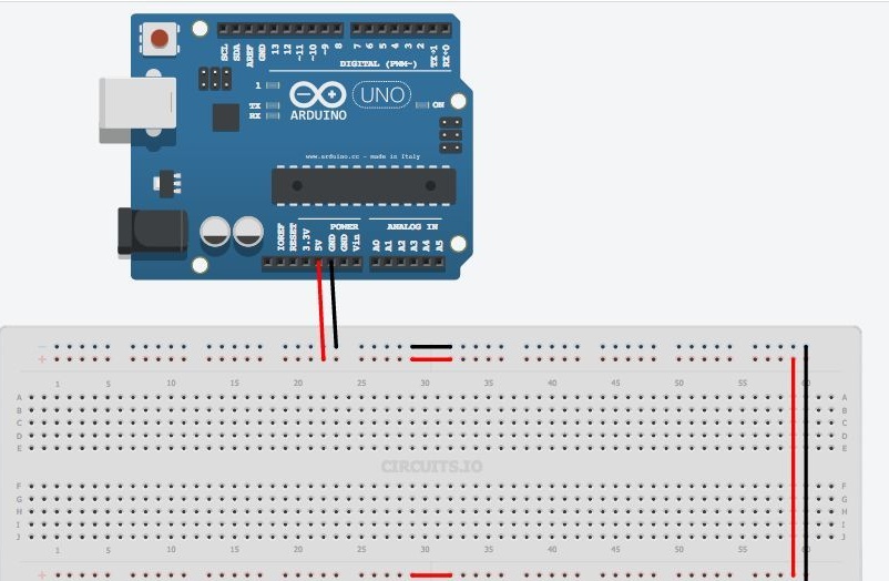
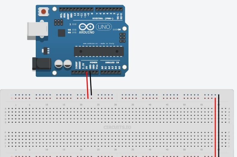
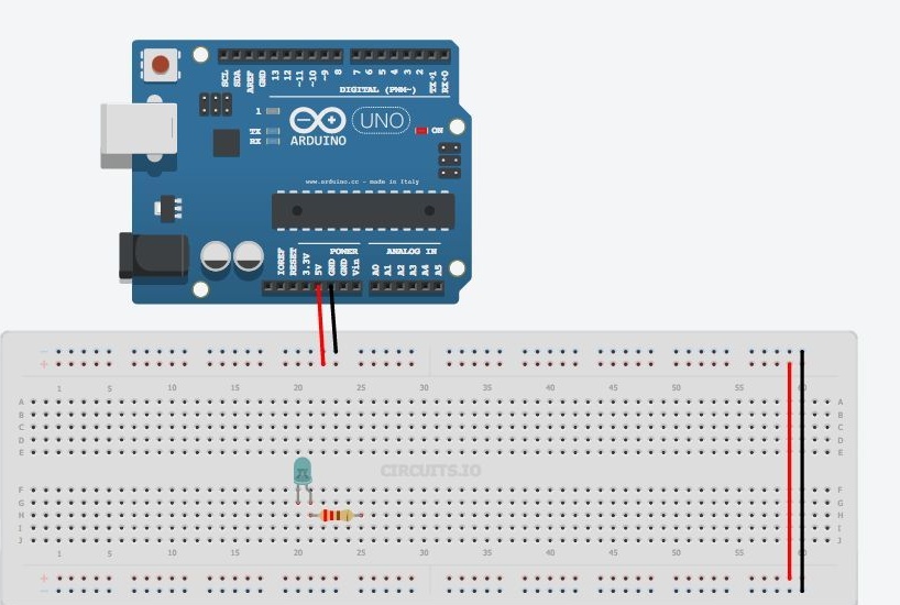
The two upper and lower rows are connected in series along the entire board. These rows are used to power the circuit. It can be 5v or 3.3v, but in any case, the first thing you need to do is connect 5v and GND to the breadboard, as shown in the figure. Sometimes these row connections can be interrupted in the middle of the board, then if you need to, you can connect them, as shown in the figure.
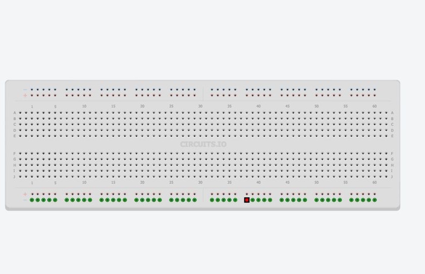
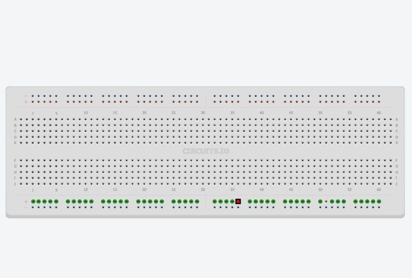

The remaining holes located in the middle of the board are grouped into five holes. They are used to connect circuit parts.
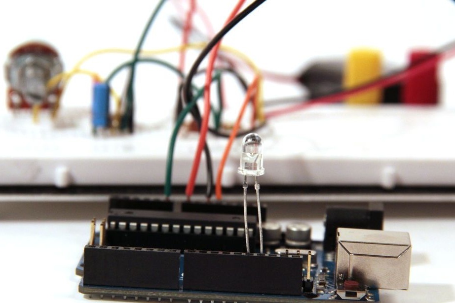
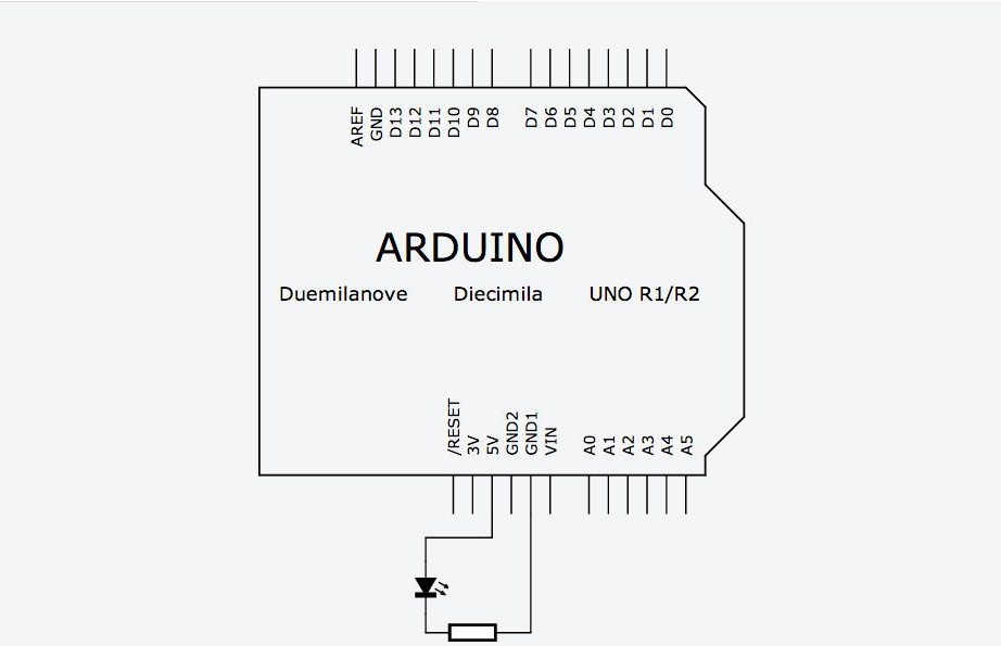
The first thing we connect to our microcontroller is the LED. The electrical connection diagram is shown in the picture.
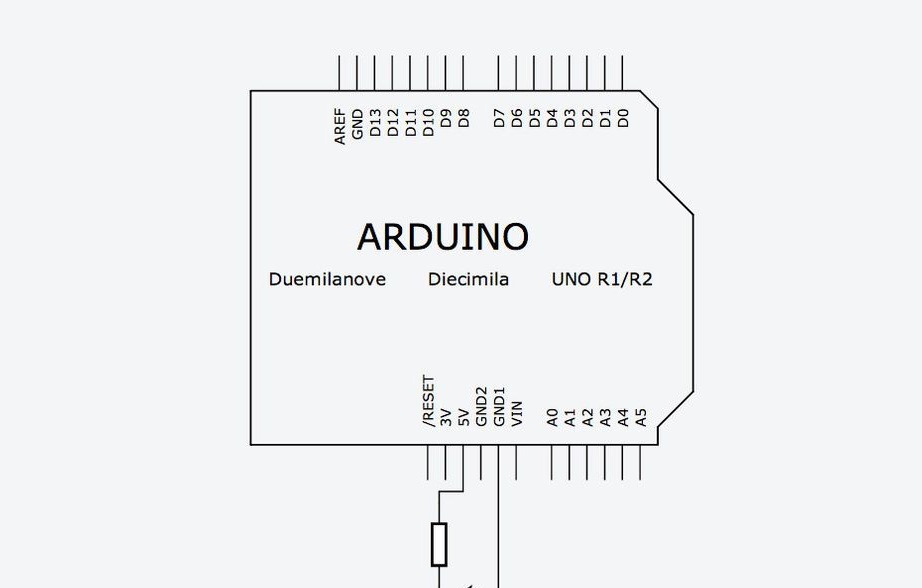
Why do I need a resistor in the circuit? In this case, it limits the current that passes through the LED. Each LED is designed for a specific current, and if this current is greater, then the LED will fail. Find out what value the resistor should be using the Ohm law. For those who do not know or have forgotten, Ohm's law says that there is a linear dependence of current on voltage. That is, the more we apply voltage to the resistor, the more current will flow through it.
V = I * R
Where V-voltage across the resistor
I- current through the resistor
R- resistance to be found.
First, we need to find out the voltage across the resistor. Most of the 3mm or 5mm LEDs that you will use have a 3V operating voltage. So, on the resistor we need to pay off 5-3 = 2v.
Then we calculate the current passing through the resistor.
Most 3 and 5mm LEDs glow at full brightness at a current of 20mA. A current more than this can disable them, and a current of lesser strength will reduce their brightness, without causing any harm.
So, we want to turn on the LED in the 5v circuit so that it has a current of 20mA. Since all the parts are included in one circuit, the resistor will also have a current of 20 mA.
We get
2V = 20 mA * R
2V = 0.02A * R
R = 100 ohms
100 Ohms is the minimum resistance, it is better to use a little more, because the LEDs have some variation in characteristics.
In this example, a 220 ohm resistor is used. Just because the author has a lot of them: wink:.
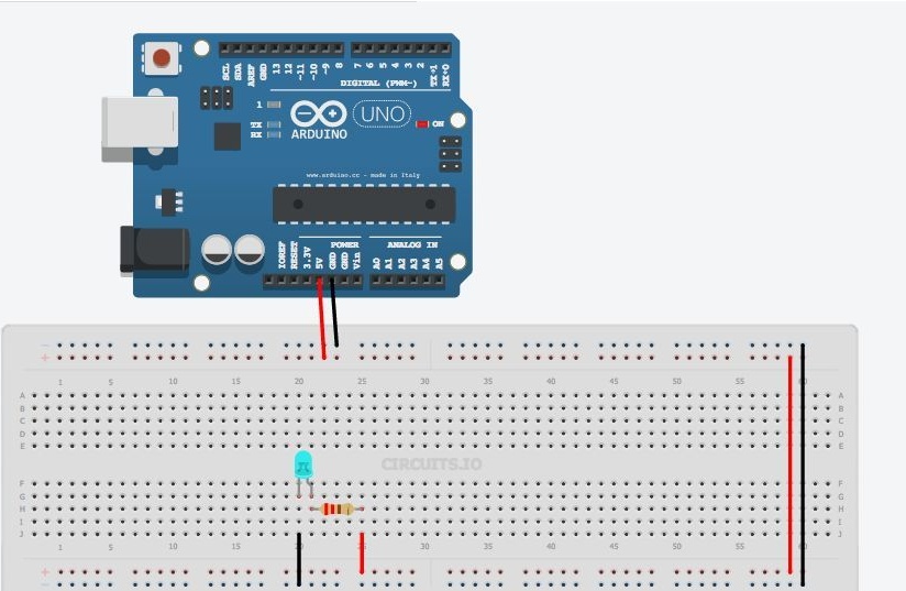
Insert the LED into the holes in the middle of the board so that its long terminal is connected to one of the terminals of the resistor. Connect the second end of the resistor to 5V, and connect the second output of the LED to GND. The LED should light up.
Please note that there is a difference in how to connect the LED. Current flows from a longer terminal to a shorter one. In the diagram it can be imagined that the current flows in the direction where the triangle is directed. Try flipping the LED and you will see that it will not light up.
But how you connect the resistor, there is no difference at all. You can turn it over or try connecting it to the other output of the LED, this will not affect the operation of the circuit. It will still limit the current through the LED.
Anatomy of an Arduino Sketch.
Programs for Arduino are called sketch. They consist of two main functions. Function setup and function loop
inside this function you will set all the basic settings. What conclusions will work on input or output, which libraries to connect, initialize variables. Function Setup () It starts only once during the sketch, when the program starts.
this is the main function that is executed after setup (). In fact, this is the program itself. This function will run indefinitely until you turn off the power.
Arduino flashing LED
In this example, we will connect a circuit with an LED to one of the Arduino digital pins and turn it on and off using the program, and you will also learn several useful functions.
- this function is used in setup () parts of the program and serves to initialize the conclusions that you will use as input (INPUT) or exit (OUTPUT). You cannot read or write data from the pin until you set it accordingly to pinMode. This function has two arguments: pinNumber- This is the pin number that you will use.
Mode- sets how the pin will work. At the entrance (INPUT) or exit (OUTPUT). To light the LED we must give a signal OF Arduino To do this, we configure the pin to exit.
- this function serves to set the state (state) pina (pinNumber). There are two main states (in general there are 3), one is High, the pin will be 5v, another is Low and the pin will be 0v. So, to light up the LED, we need to set a high level on the pin connected to the LED High.
- delay. Serves to delay the program for a specified period in ms.
Below is the code that causes the LED to flash.
// LED Blink

int ledPin = 7; // Arduino pin to which the LED is connected

void setup () {
  pinMode (ledPin, OUTPUT); // set the pin as EXIT
}

void loop () {
  digitalWrite (ledPin, HIGH); // light the LED
  delay (1000); // delay 1000 ms (1 sec)
  digitalWrite (ledPin, LOW); // Turn off the LED
  delay (1000); // wait 1 sec
}
A little explanation on the code.
Lines that begin with "//" are comments by Arduino that ignore them.
All commands end with a semicolon; if you forget them, you will receive an error message.
ledpinis a variable. Variables are used in programs to store values. In this example, the variable ledpin assigned a value of 7, this is the pin number of the Arduino. When the Arduino in the program encounters a string with a variable ledpin , it will use the value that we specified earlier.
So record pinMode (ledPin, OUTPUT) similar to record pinMode (7, OUTPUT).
But in the first case, it’s enough for you to change the variable and it will change in each line where it is used, and in the second case, in order to change the variable, you have to make changes in the pens in each command.
in the first line indicates the type of variable. When programming Arduino, it is important to always declare the type of variables. For now, it’s enough for you to know that INT announces negative and positive numbers.
Below is presented modeling sketch. Press start to view the operation of the circuit.

As expected, the LED turns off and lights up after one second. Try changing the delay to see how it works.
Management of several LEDs.
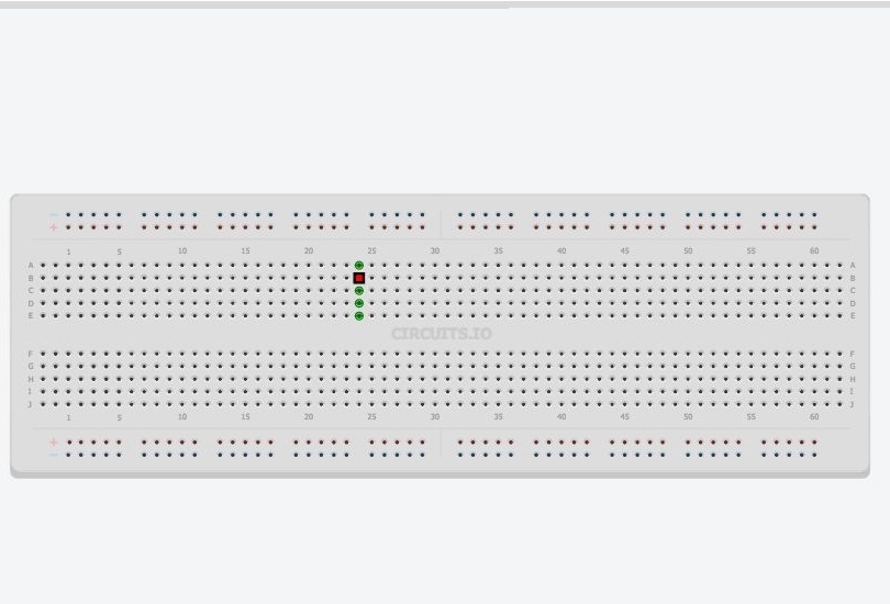
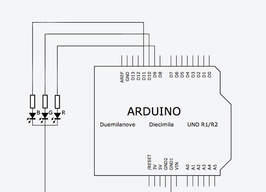
In this example, you will learn how to control multiple LEDs. To do this, install 3 more LEDs on the board and connect them to the Arduino resistors and pins, as shown below.
In order to turn on and off the LEDs in turn, you need to write a program like this:
// Multi LED Blink

int led1Pin = 4;
int led2Pin = 5;
int led3Pin = 6;
int led4Pin = 7;

void setup () {
  // set pins as EXIT
  pinMode (led1Pin, OUTPUT);
  pinMode (led2Pin, OUTPUT);
  pinMode (led3Pin, OUTPUT);
  pinMode (led4Pin, OUTPUT);
}

void loop () {
  digitalWrite (led1Pin, HIGH); // light the LED
  delay (1000); // delay 1 sec
  digitalWrite (led1Pin, LOW); // put out the LED
  delay (1000); // delay 1 sec

  // do the same for the other 3 LEDs
  digitalWrite (led2Pin, HIGH); // light the LED
  delay (1000); // delay 1 sec
  digitalWrite (led2Pin, LOW); // put out the LED
  delay (1000); // delay 1 sec

  digitalWrite (led3Pin, HIGH); // light the LED
  delay (1000); // delay 1 sec
  digitalWrite (led3Pin, LOW); // put out the LED
  delay (1000); // delay 1 sec

  digitalWrite (led4Pin, HIGH); // light the LED
  delay (1000); // delay 1 sec
  digitalWrite (led4Pin, LOW); // put out the LED
  delay (1000); // delay 1 sec
}
This program will work fine, but this is not the most rational solution. The code needs to be changed. In order for the program to work over and over again, we will use the construct called.
Cycles are convenient when you need to repeat the same action several times. In the code above, we repeat the lines
digitalWrite (led4Pin, HIGH);
delay (1000);
digitalWrite (led4Pin, LOW);
delay (1000);
full sketch code in the attachment
LED brightness adjustment
Sometimes you will need to change the brightness of the LEDs in the program. This can be done using the command analogWrite (). This command turns the LED on and off so quickly that the eye does not see this flicker. If the LED is turned on half the time and half off, it will visually appear that it is lit at half its brightness. This is called pulse width modulation (PWM or PWM in English). PWM is used quite often, since it can be used to control the “analog” component using a digital code. Not all Arduino pins are suitable for these purposes. Only those conclusions around which such designation is drawn "~"You will see it next to pins 3,5,6,9,10,11.
Connect one of your LEDs to one of the PWM outputs (for the author, this is pin 9). Now run the sketch flashing LED, but first change the command digitalWrite () on the analogWrite (). analogWrite () It has two arguments: the first is the pin number, and the second is the PWM value (0-255), as applied to LEDs, this will be their brightness, and for electric motors, rotation speed. Below is an example code for different LED brightness.
// Change the brightness of the LED

int ledPin = 9; // LED connected to this pin
void setup () {
  pinMode (ledPin, OUTPUT); // initialize the pin to output
}

void loop () {
  analogWrite (ledPin, 255); // full brightness (255/255 = 1)
  delay (1000); // pause 1 sec
  digitalWrite (ledPin, LOW); // turn off the LED
  delay (1000); // pause 1 sec

  analogWrite (ledPin, 191); // brightness at 3/4 (191/255 ~ = 0.75)
  delay (1000); // pause 1 sec
  digitalWrite (ledPin, LOW); // turn off the LED
  delay (1000); // pause 1 sec

  analogWrite (ledPin, 127); // half brightness (127/255 ~ = 0.5)
  delay (1000); // pause 1 sec
  digitalWrite (ledPin, LOW); // turn off the LED
  delay (1000); // pause 1 sec

  analogWrite (ledPin, 63); // quarter brightness (63/255 ~ = 0.25)
  delay (1000); // pause 1 sec
  digitalWrite (ledPin, LOW); // turn off the LED
  delay (1000); // pause 1 sec
}
Try changing the PWM value in the command analogWrite ()to see how it affects brightness.
Next, you will learn how to adjust the brightness smoothly from full to zero. You can, of course, copy a piece of code 255 times
analogWrite (ledPin, brightness);
delay (5); // short delay
brightness = brightness + 1;
But, you understand - it will not be practical. To do this, it is best to use the FOR loop that was used previously.
The following example uses two cycles, one to reduce brightness from 255 to 0
for (int brightness = 0; brightness = 0; brightness -) {

analogWrite (ledPin, brightness);
delay (5);

}
delay (5) used to slow down the rate of rise and fall of brightness 5 * 256 = 1280 ms = 1.28 sec.)
The first line uses "brightness-"so that the brightness value decreases by 1, each time the cycle repeats. Please note that the cycle will work as long as brightness> = 0. Replacing the sign > on the sign >= we included 0 in the brightness range. This sketch is modeled below.
// smoothly change the brightness

int ledPin = 9; // LED is connected to this pin

void setup () {
  pinMode (ledPin, OUTPUT); // initialize the pin to exit
}

void loop () {
  // gradually increase the brightness (0 to 255)
  for (int brightness = 0; brightness = 0; brightness -) {
    analogWrite (ledPin, brightness);
    delay (5);
  }

  delay (1000); // wait 1 sec
 // smoothly decrease the brightness (255 to 0)
  for (int brightness = 255; brightness> = 0; brightness -) {
    analogWrite (ledPin, brightness);
    delay (5);
  }

  delay (1000); // wait 1 sec
}
}
This is not very visible, but the idea is clear.
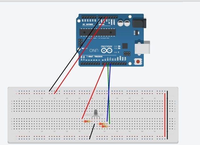
RGB LED and Arduino
The RGB LED is actually three LEDs of different colors in one housing.
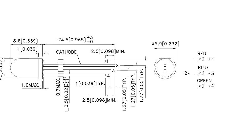
Including different LEDs with different brightness, you can combine and get different colors. For Arduino, where the number of gradations of brightness is 256, you get 256 ^ 3 = 16581375 possible colors. In reality, of course, there will be fewer of them.
The LED that we will use is the common cathode. Those. all three LEDs are structurally connected by cathodes to one terminal. We will connect this pin to the GND pin. The remaining terminals, through the limiting resistors, must be connected to the PWM terminals. The author used conclusions 9-11. Thus, it will be possible to control each LED separately. The first sketch shows how to turn on each LED separately.
// RGB LED - test

// pin connections
int red = 9;
int green = 10;
int blue = 11;

void setup () {
  pinMode (red, OUTPUT);
  pinMode (blue, OUTPUT);
  pinMode (green, OUTPUT);
}

void loop () {
  // turn on / off the red LED
  digitalWrite (red, HIGH);
  delay (500);
  digitalWrite (red, LOW);
  delay (500);

  // turn on / off the green LED
  digitalWrite (green, HIGH);
  delay (500);
  digitalWrite (green, LOW);
  delay (500);

  // turn on / off the blue LED
  digitalWrite (blue, HIGH);
  delay (500);
  digitalWrite (blue, LOW);
  delay (500);
}
The following example uses the commands analogWrite () and to get various random brightness values for LEDs. You will see different colors changing randomly.
// RGB LED - random colors

// pin connections
int red = 9;
int green = 10;
int blue = 11;
void setup () {
  pinMode (red, OUTPUT);
  pinMode (blue, OUTPUT);
  pinMode (green, OUTPUT);
}
void loop () {
  // pick a random color
  analogWrite (red, random (256));
  analogWrite (blue, random (256));
  analogWrite (green, random (256));
  delay (1000); // wait one second
}
Random (256)-Returns a random number in the range from 0 to 255.
There is a sketch in the attached file, which will demonstrate smooth transitions of colors from red to green, then to blue, red, green, etc.
An example sketch works, but there is a lot of repeating code. You can simplify the code by writing your own helper function, which will smoothly change one color to another.
Here's what it will look like:
Let's look at the definition of a function in parts. Function called fader and has two arguments. Each argument is separated by a comma and has a type declared in the first line of the function definition: void fader (int color1, int color2). You see that both arguments are declared as int, and they are given names color1 and color2 as conditional variables for defining a function. Void means that the function does not return any values, it simply executes commands. If it were necessary to write a function that returned the result of the multiplication, it would look like this:
int multiplier (int number1, int number2) {

int product = number1 * number2;
return product;

}
Notice how we declared Type int as return type instead
void.
Inside the function there are commands that you already used in the previous sketch, only the pin numbers were replaced by color1 and color2. Function called fader, its arguments are calculated as color1 = red and color2 = green. The archive full sketch using functions
Button
In the next sketch, a button with normally open contacts will be used, without fixing.
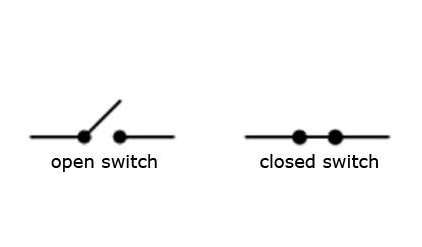
This means that while the button is not pressed, the current does not flow through it, and after releasing, the button returns to its original position.
In the circuit, in addition to the button, a resistor is used. In this case, it does not limit the current, but "pulls" the button to 0v (GND). Those. until the button is pressed on the pin of the Arduino to which it is connected, the level will be low. The resistor used in the 10 kΩ circuit.
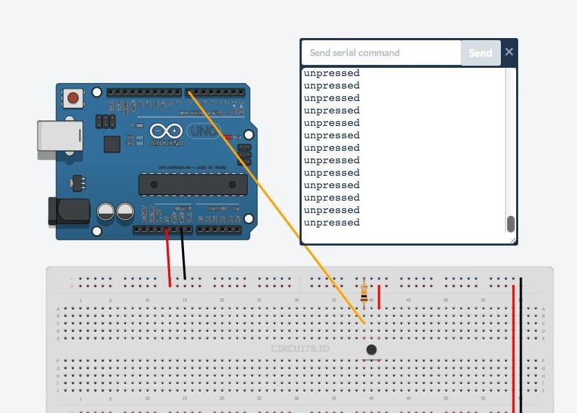
// define the button click
int buttonPin = 7;
void setup () {
  pinMode (buttonPin, INPUT); // initialize the input pin
  Serial.begin (9600); // initialize the serial port
}
void loop () {
  if (digitalRead (buttonPin) == HIGH) {// if the button is pressed
    Serial.println ("pressed"); // print "pressed"
  } else {
    Serial.println ("unpressed"); // otherwise "unpressed"
  }
}
There are several new teams in this sketch.
-This command takes the value High (high level) and low (low level) of the output that we are checking. Previously, in setup (), this output must be configured for input.
; // where buttonPin is the pin number where the button is connected.
The serial port allows you to send Arduino messages to the computer, while the controller itself runs the program. This is useful for debugging a program, sending messages to other devices or applications. To enable data transfer via the serial port (also known as UART or USART), you must initialize it in setup ()
Serial.begin () has only one argument is the data transfer rate between the Arduino and the computer.
sketch, a command is used to display a message on the screen in the Arduino IDE (Tools >> Serial Monitor).
- the design allows you to control the progress of the program by combining several checks in one place.
If (if) digitalRead returns HIGH, then the word "pressed" is displayed on the monitor. Else (otherwise) the word "squeezed" is displayed on the monitor. Now you can try turning the LED on and off at the touch of a button.
// button press detection with LED output
int buttonPin = 7;
int ledPin = 8;
void setup () {
  pinMode (buttonPin, INPUT); // this time we will set button pin as INPUT
  pinMode (ledPin, OUTPUT);
  Serial.begin (9600);
}
void loop () {
  if (digitalRead (buttonPin) == HIGH) {
    digitalWrite (ledPin, HIGH);
    Serial.println ("pressed");
  } else {
    digitalWrite (ledPin, LOW);
    Serial.println ("unpressed");
  }
}Analog input.
analogRead allows you to read data from one of the Arduino analog pins and displays a value in the range from 0 (0V) to 1023 (5V). If the voltage at the analog input is 2.5V, then 2.5 / 5 * 1023 = 512 will be printed
analogRead has only one argument- This is the analog input number (A0-A5). The following sketch provides a code for reading voltage from a potentiometer. To do this, connect a variable resistor, the extreme pins to pins 5V and GND, and the middle pin to input A0.

Run the following code and look in the serial monitor how the values change depending on the rotation of the resistor knob.
// analog input

int potPin = A0; // the central output of the potentiometer is connected to this pin

void setup () {
  // the analog pin is enabled by input by default, so initialization is not needed
  Serial.begin (9600);
}

void loop () {
  int potVal = analogRead (potPin); // potVal is a number between 0 and 1023
  Serial.println (potVal);
}
The next sketch combines a button-click sketch and a LED brightness control sketch. The LED will turn on from the button, and the potentiometer will control the brightness of the glow.
// button press detection with LED output and variable intensity
int buttonPin = 7;
int ledPin = 9;
int potPin = A0;
void setup () {
  pinMode (buttonPin, INPUT);
  pinMode (ledPin, OUTPUT);
  Serial.begin (9600);
}
void loop () {
  if (digitalRead (buttonPin) == HIGH) {// if button pressed
    int analogVal = analogRead (potPin);
    int scaledVal = map (analogVal, 0, 1023, 0, 255);
    analogWrite (ledPin, scaledVal); // turn on led with intensity set by pot
    Serial.println ("pressed");
  } else {
    digitalWrite (ledPin, LOW); // turn off if button is not pressed
    Serial.println ("unpressed");
  }
}