
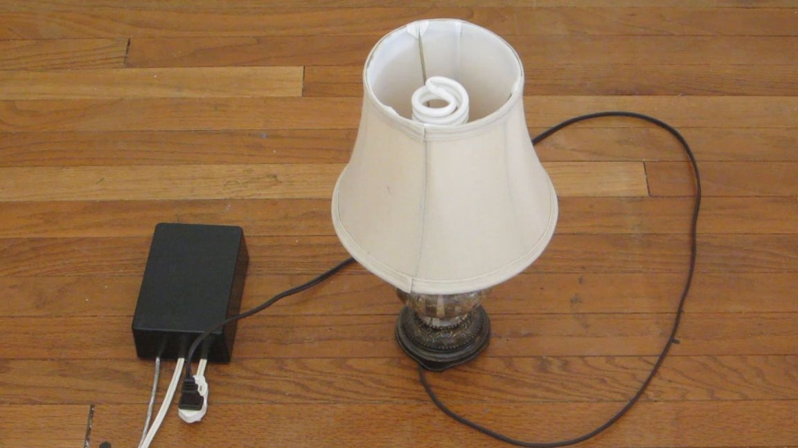
Clapper (from the English clap) was popular in the 80s and 90s. The device allows you to control the light with ordinary clap. However, the invention was not perfect, and had some limitations. The clapper was triggered by various noise, and accidentally turned off the lights and devices, it was also not possible to control more than one device.
By creating a similar device based on Arduino, allows you to set a code for each device, and eliminates false positives, it will also be able to control several outlets at the same time. Each device will operate on a different sequence of pops.
Arduino will provide the ability to set the time interval for turning on and off the outlet. For example, to reboot the router, you need to program the socket to turn off for 10 seconds and then turn it back on. Or, you can turn on heating for the desired number of minutes, and then automatically turn it off.
Materials:
- Arduino Uno
- Field effect transistor 1 pc
- Diode 1 pc
- Capacitor 0.1 uF 1 pc
- Resistor 10 kOhm 2 pcs
- Resistor 100 kOhm 1 pc
- Electret microphone 1 pc
- Relay 1 pc
- 1 pc switch
- Socket 1 pc
- fork 1 pc
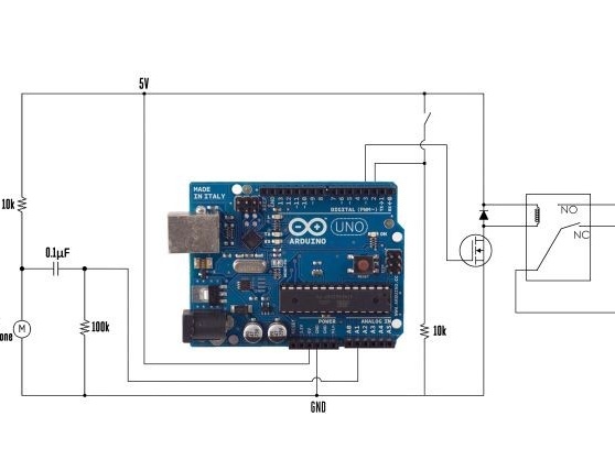
Step one. Scheme.
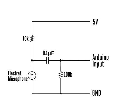
The microphone control circuit is a microphone itself, a condenser and two resistors. At that moment, when the microphone catches the vibration of sound, then the output voltage changes. The signal is fed to the analog output of the Arduino board and is already being processed there.
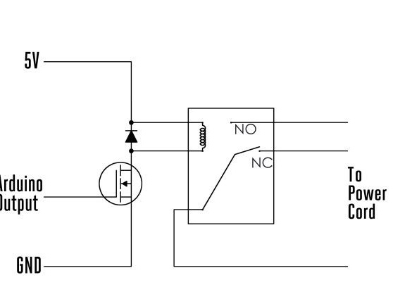
The relay module contains a relay, a diode, and a MOSFET. A power transistor has been added to the circuit, since the relay requires more current than the Arduino microcontroller produces. Therefore, the signal issued by the board will activate the transistor, in turn, it will supply power to the relay to turn it on. The relay acts as an AC switch, and turns on the power outlet. The blocking element is a diode, which protects the Arduino from a voltage surge when the device is turned off. In order not to assemble the relay module, you can use the PowerSwitch Tail board or an industrial relay shield.
To reprogram the clap sequence without modifying the code, connect the switch to the second pin. It connects the second pin to ground in operating mode, and to 5V power to make changes in program mode.
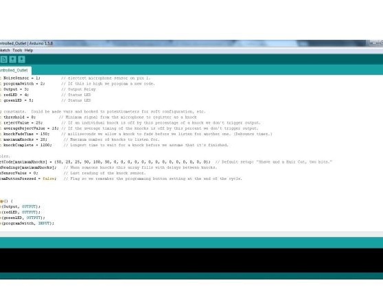
Step Two Program code.
The code can be downloaded attached under the article without changes. If there is a desire, threshold values are changed that will determine the sensitivity of the sensor.
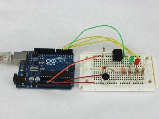
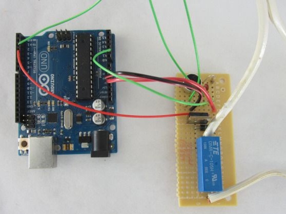
Step Three Prototype circuitry on a breadboard.
Before soldering on a printed circuit board, the author assembles a project on a breadboard. This gives him the opportunity to make the necessary settings and changes in the program code.
First of all, he checks the microphone control circuit together with the microcontroller. For this, LEDs are connected to the 3, 4 and 5 pins. The LEDs light up with the correct sequence of pops.
Also adjusts the microphone sensitivity. In the program code, the value of the threshold variable changes.
When the author was sure that this unit was working correctly, he set about assembling the relay module. No additional adjustments are required in this part of the circuit.
Note: Do not connect the device to an AC source until the board is placed in the protective case.
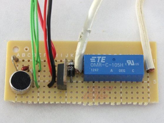
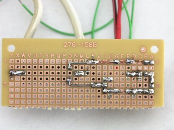
The fourth step. PCB soldering.
After a complete check of the circuit's operability, it is soldered on the printed circuit board (perforated can be used). Next, the board is connected to the Arduino using wire jumpers.
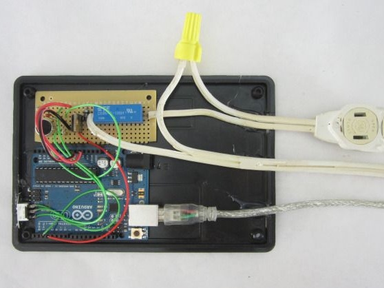
Step Five Installing components in a chassis.
The case for this device must be insulated electrically, because the voltage of 120 VAC (voltage of outlets in the country of the author) is very dangerous.
To fix the board inside, the author uses hot glue.
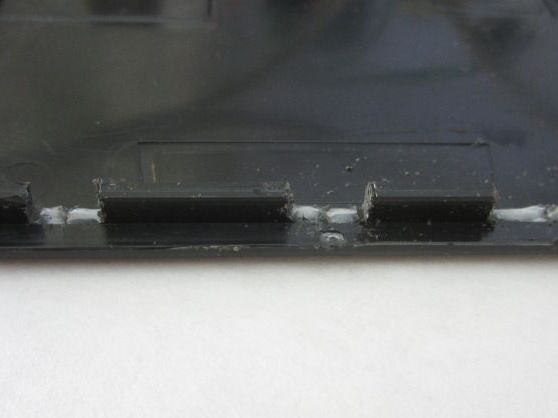
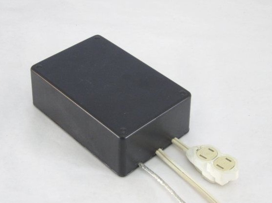
In the case, you need to cut openings for cables. Cables and the circuit breaker are in place, their position is marked on both sides. Using a nail file for thin cuts, cut out slots a little larger than the diameter of the wires. Another slot is made for the switch. The wires with the switch are placed in the places prepared for them, and fixed with hot glue, after which the case is closed.
If the sensor does not work, you may need to drill more holes so that the sound reaches the microphone better.
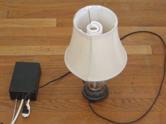
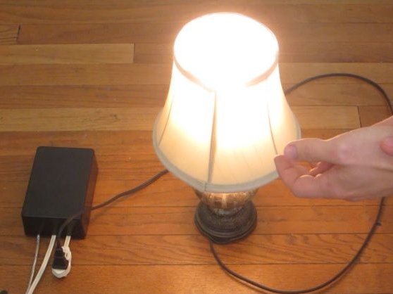
Step Six Device management.
Now the most interesting part at the end of the work done. An electrical device is connected and an encoded sequence of pops is produced. You can activate the outlet not only with a pop, but also with other noise that exceeds the threshold value. By default, in the test code, the clap sequence is similar to a “dog waltz”. In this code, the device should turn on for 10 seconds, and then turn off automatically. The code can be modified independently, for example, to increase the duration of inclusion, it all depends on your preferences.
Due to the fact that the outlet is activated by a certain sequence of pops, this makes it possible to control several outlets using one microcontroller. It is also possible to control several relay modules. There is an option to power the main circuit from an AC source via a 5V USB converter, which is installed inside the case. Please note that all connections must be securely insulated.
Video with the assembly and operation of the device: