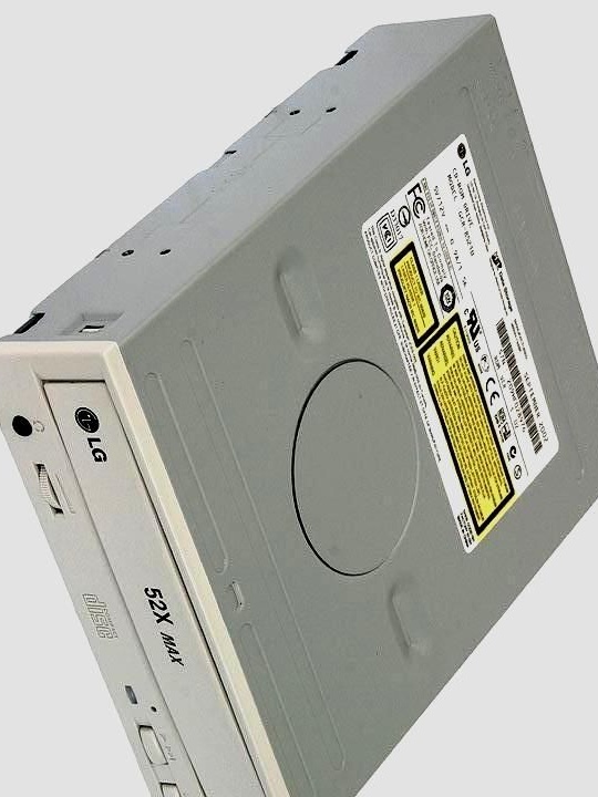
This article will discuss how to make a device that facilitates the manufacture of printed circuit boards from a CD or DVD drive. For his device, the author used a CD-ROM from LG.
Tools and materials:
-CD-ROM;
- Metal sleeve with internal thread;
-Clerical paper clip;
-Two terminals;
-Resistor 330-1pcs;
-Resistor 1k-2pcs;
Transistor KT805BM;
Transistor C945;
Capacitor 0.1 uF;
-Diode;
-Light-emitting diode;
-Connector;
-Zener diode BZX85C6V8;
-Wire;
-Heat-shrink tubing;
-Soldering iron;
- metalwork tool;
-Power Supply;
Step One: Disassembly
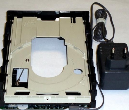
First, the author disassembles the drive. For the device, it leaves the front board, movable tray, plastic base, motor and gearbox. The remaining parts are not needed and the author deletes them.
Step Two: Mechanical
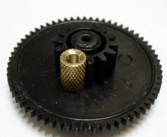
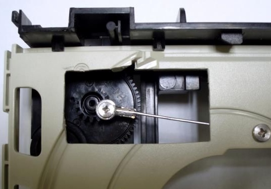
Removes gears. Removes two teeth from the large gear, which transmitted force to the tray rail. In place of the removed teeth, a threaded sleeve is attached.
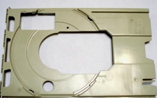
Cuts the rail from the tray.
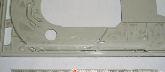
Then in the tray makes a hole 20 * 40 mm.
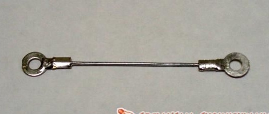
A connecting rod is made of a paper clip and two terminals. For durability, tin-off joints.
Assembles a gearbox.
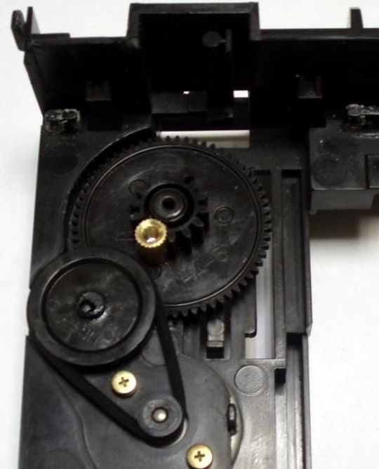
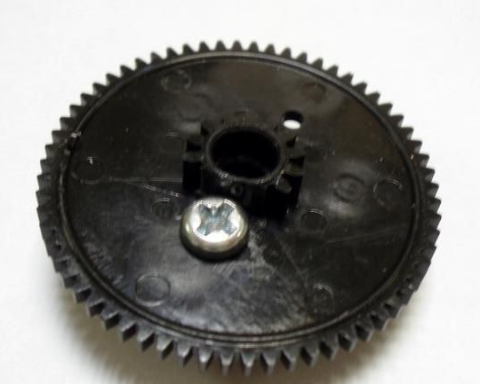
Fastens the connecting rod. The screw that is screwed into the bushing should be so long that it would abut when tightening and the connecting rod eye would spin freely around it. The second eye is firmly attached to the tray. It checks the operation of the mechanical part, adjusts the parts if necessary, so that no matter where or what clings.
Step Three: The Electrical Part
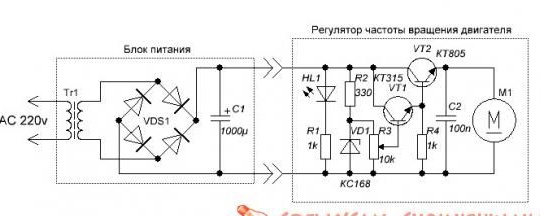
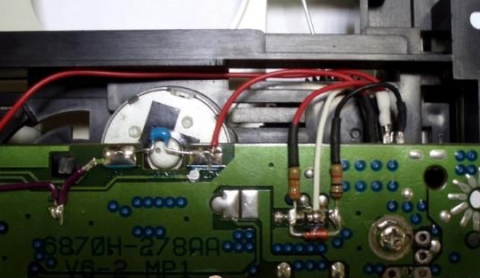
Further, the author collects a stabilizer, with voltage adjustment from 0 to 6.5V, according to the diagram below.
To do this, removes all components from the board except for the variable resistor.
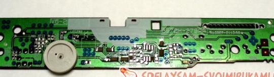
The circuit collects mounted installation. Unused tracks must be torn.
The author connects two sections of the resistor in parallel. Due to the fact that the current is small, you can do without additional cooling of the regulator transistors.
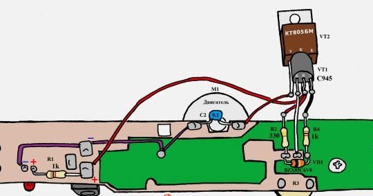
Transistors are installed on the reverse side of the board, the ends are insulated by heat shrink.
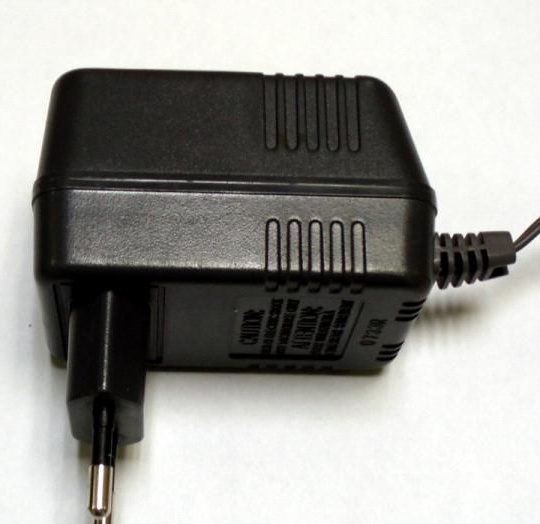
The author used the power supply from the base of the phone. The parameters of the power supply should be in the range of 7.5-12 volts.
The device is ready.For the solution, the author used plastic ice cream trays. About 150 ml of solution was poured into the bath.
From the author’s experience in using the device:
-reducing etching time of boards
etching uniformity
- the absence of "poisons" and "overshoots"