

In connection with the requirements of the "Rules of the Road", all cars must move with the dipped headlights on. In the daytime, the indication lamps for the inclusion of outdoor lighting on the instrument panel of the car are practically not visible, and the sound indication is most often absent.
Therefore, some motorists, due to carelessness, sometimes have problems. Some simply forget to turn on the light at the beginning of the movement and therefore are punished by the traffic police inspector. Or they forget to turn off the headlights when the engine is stopped, which, when parked for a long time, leads to a significant discharge of the battery so much that it will not be possible to start the engine.
Citizens on foreign cars, this topic is irrelevant, their problems prevented the hardworking inhabitants of the Middle Kingdom. But to some motorists of the domestic auto industry, to date, these "misunderstandings" periodically spoil a lot of nerves. For them, it is proposed to manufacture a simple compact and economical warning sound indication device. It reminds the driver of the need to turn on the low beam at the beginning of the movement, and also warns about the headlights not turned off when stopping.
Signaling modes:
The engine is on, the headlights are off - a periodic beep reminds the driver to turn on the headlights.
When you turn on the headlights and the engine is running - the sound signal stops and the LED indicator for the presence of a dipped beam lights up.
The engine is turned off, but the headlights are on - a periodic sound signal for 20 seconds, the LED indicator for the presence of low beam (until the headlights turn off) lights up. The timer is configurable, it is possible to disable the timer.
An additional function is the appearance of a periodic sound signal (of a different frequency) when a sensor is triggered (reverse, open door, ...). A sound appears in this signaling device and its LED indicator lights up when the hand brake is applied when the engine is running (short stop - traffic light, railway crossing).
When the ignition is turned off and the dipped beam, the indicator does not consume current.
The circuit of this signaling device is made on simple logic, does not contain imported, special and expensive components; it will not be difficult to make it yourself.
Alarm circuit
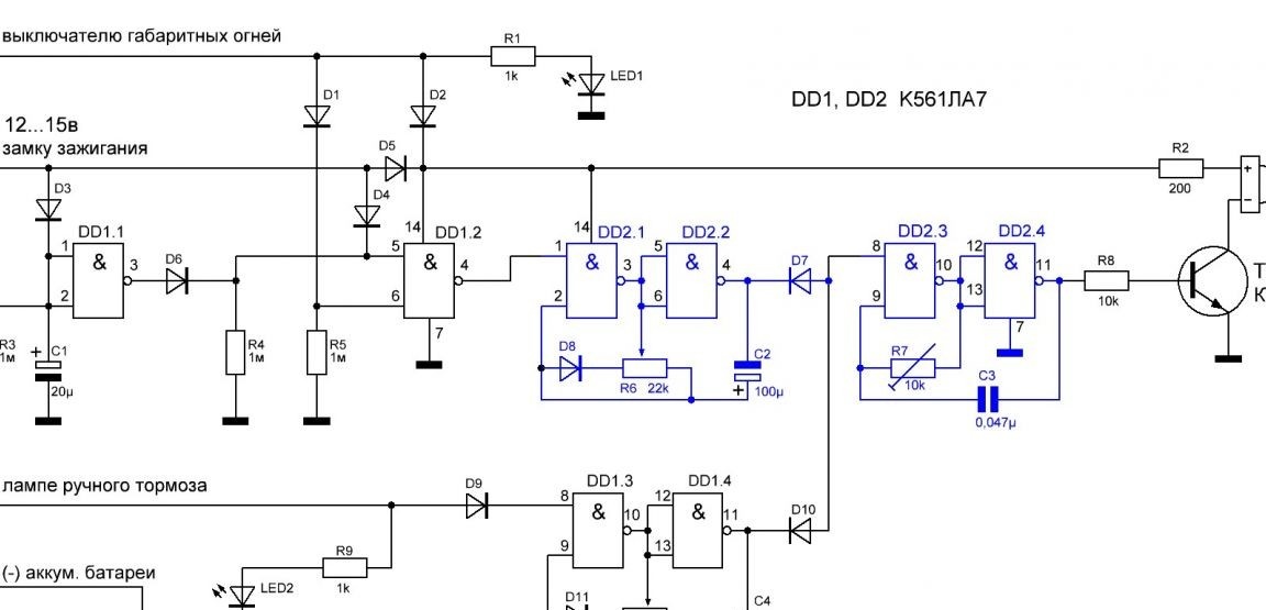
The signaling device is assembled on two K561LA7 microcircuits, which maintain their operability at a supply voltage of 5 to 15 ... 18 V. On the Internet, signaling devices with similar functions performed on a single microcircuit are offered. But saving on the second microcircuit 20-30 rubles, we get annoying constant sound with limited tuning and the lack of additional signaling capabilities.
Element DD1.1 with resistor R3 and capacitor C1 is a timer that limits the duration of the sound generator so that the driver can leave the vehicle's side lights on without a sound signal, for example, during night parking. Element DD1.2 acts as a control element that enables the operation of the generator. On the elements of the chip DD2 assembled a generator of a periodic sound signal.
Alarm Manufacturing
1. The operation of the sound generator.
The sound frequency generator (SP) is assembled according to a typical circuit on the logic elements DD2.3 and DD2.4. The frequency of the generator is determined by R7 and C3. To configure a pleasant timbre of sound, a build-in resistor R7 is installed. At the end of the setup, you can measure the resistance value with a tester and replace it with a constant resistor.
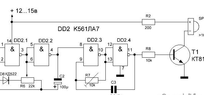
The operation of the SP generator is controlled by a second low-frequency generator on the elements DD2.1 and DD2.2. By selecting the capacitance C2 (100 - 220 μf) and adjusting the operation of the generator using a variable resistor R6, it is possible to form short (up to 0.5 sec) pulses with pauses of 1 ... 300 sec.
2. Assembly and tuning of the sound generator.
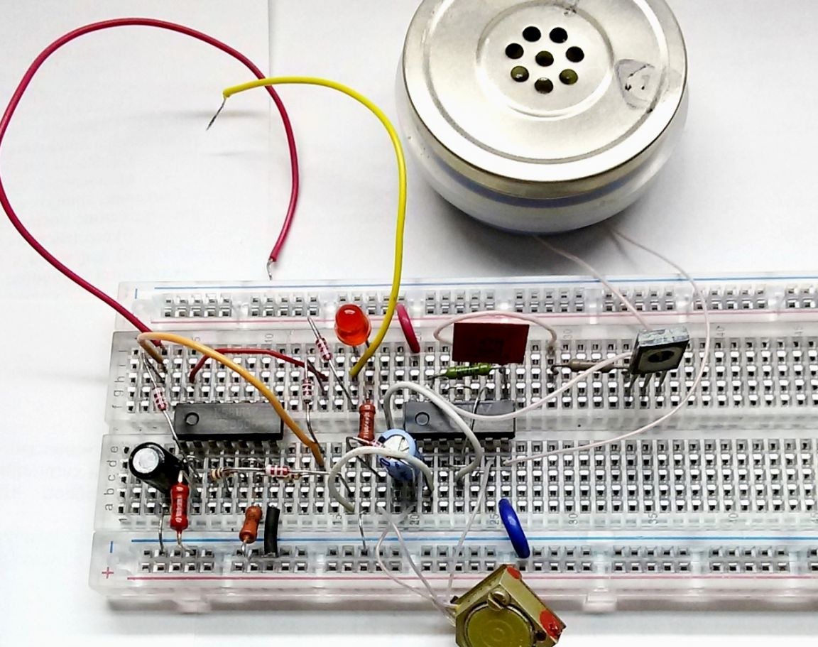
To check and configure the circuit, we collect both generators on the circuit board.
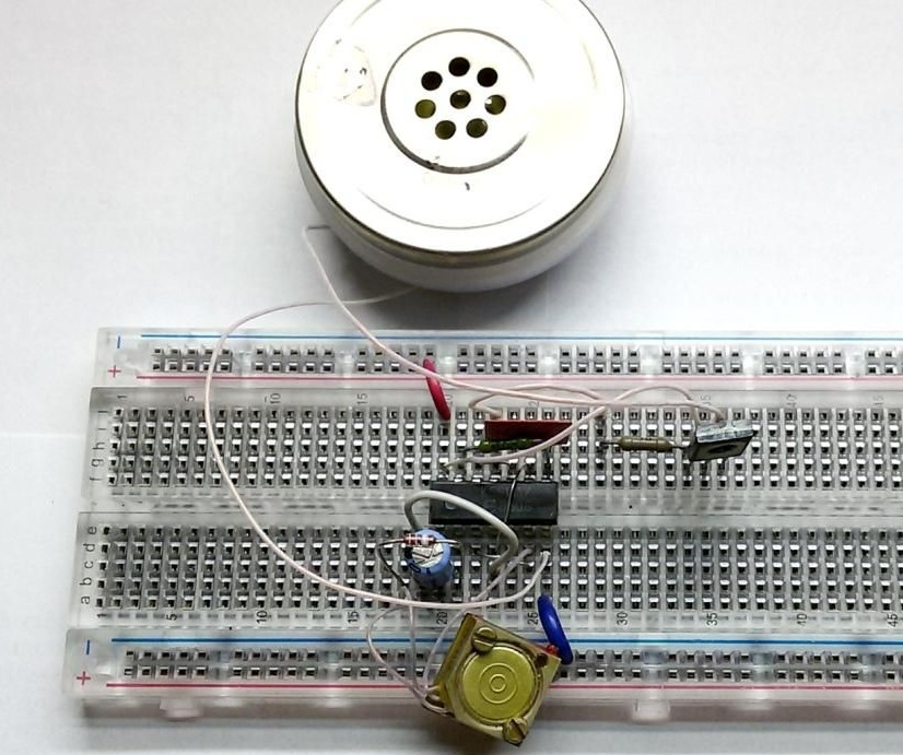
The volume of the signal is amplified by the transistor T1. As the load of the amplifier, you can use a dynamic head, earphone or head from an old handset with a resistance of 16 ... 50 ohms. When both generators work together, short tones are generated. We adjust the tone and frequency of the signals.
3. Assembly and debugging of the signaling device.
To check and debug the operation of the signaling device, we collect the rest of the circuit on the circuit board.
4. Check the operation of the alarm logic.
Upon receipt of the K561LA7 chip at both inputs, the logic is “1”, and its output will be a logical “0”. With other combinations of levels at the inputs - a logical "1" at the output.
When the ignition is turned on, the voltage of the on-board network goes to input 5 of the element DD1.2, i.e. a logical “1” appears on it. When the dipped beam and the side lights (hereinafter referred to as lighting) are switched off, there is a logical “0” at the input 6 of the DD1.2 element connected via R5 to the battery minus. As a result, at output 4, a logical “1” is set allowing the operation of the generator. Element DD1.1 does not affect the operation of the generator, because has an output log. "0". A periodic beep sounds to remind the driver to turn on the headlights.
When you turn on the lighting, at the input 6 of the element DD1.2, log. "0" is replaced with a log. “1”, and output 4 sets the log. "0" prohibiting the operation of the generator. The signaling device is "silent." The dipped beam LED is on.
When the ignition is turned off, a log is set at input 5 of the DD1.2 element. "0". Because when the lighting is not turned off, at the input 6 of the DD1.2 element the log remains. “1”, at output 4, the log level appears. "1" allowing the generator to work. A periodic beep sounds to remind the driver to turn off the headlights.
But this also stops the supply of voltage to the inputs DD1.1. The capacitor C1 is gradually discharged through the resistor R3. Upon reaching the inputs of the element DD1.1 level log. "0", at output 3, the log level appears. "1", prohibiting the operation of the generator. With the ratings C1 and R3 indicated on the diagram, the generator operating time is approximately 20 seconds, which is enough to remind the driver of the dipped beam on.
If the ignition is switched on when the ignition is switched on, the signal from the low-frequency generator on elements DD1.3, DD1. 4 (performed on the free elements of DD1) will allow the operation of the SP generator on the elements DD2.3, DD2.4. To avoid confusion of the source, the frequency of this signal is individually set using R10, D11 and C4.
When the lighting and ignition are turned off, the power supply to the microcircuits through the diodes D2 and D5 ceases, the signaling device is turned off.
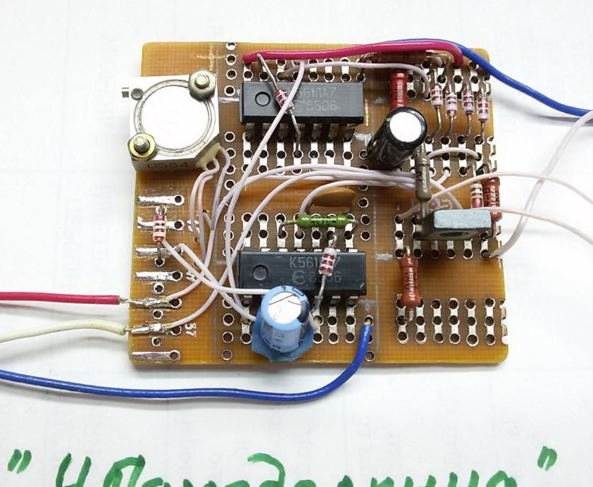
5. Installation of the debugged circuit of the signaling device on the working board.
We are preparing a board for mounting and soldering parts. To do this, cut out the required size from the universal board, clean and tidy the contact tracks.

We transfer the parts from the circuit board to the working one, solder the parts, perform the missing wiring of the connections with a thin mounting wire.
The signaling device can be assembled in any convenient way, including hinged mounting. When installed without errors and serviceable parts, it starts working immediately after switching on.
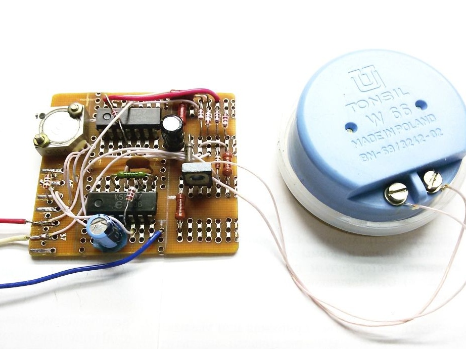
We connect the sound head and test the operation of the signaling device.
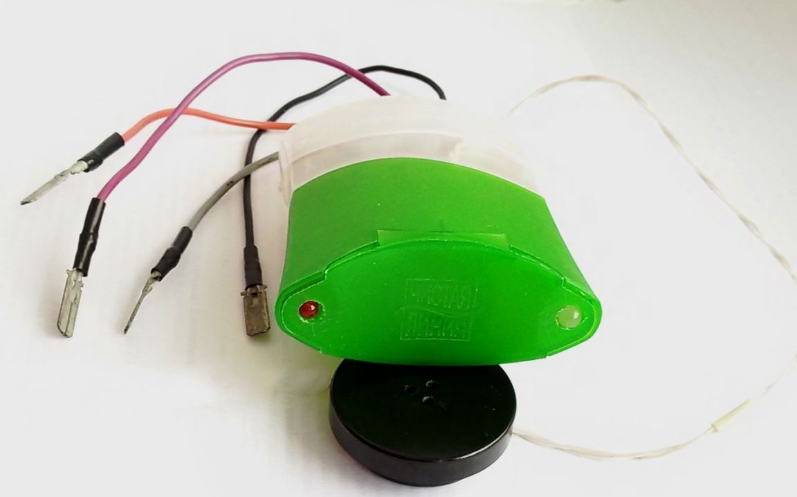
6. Installing the alarm board into the housing.
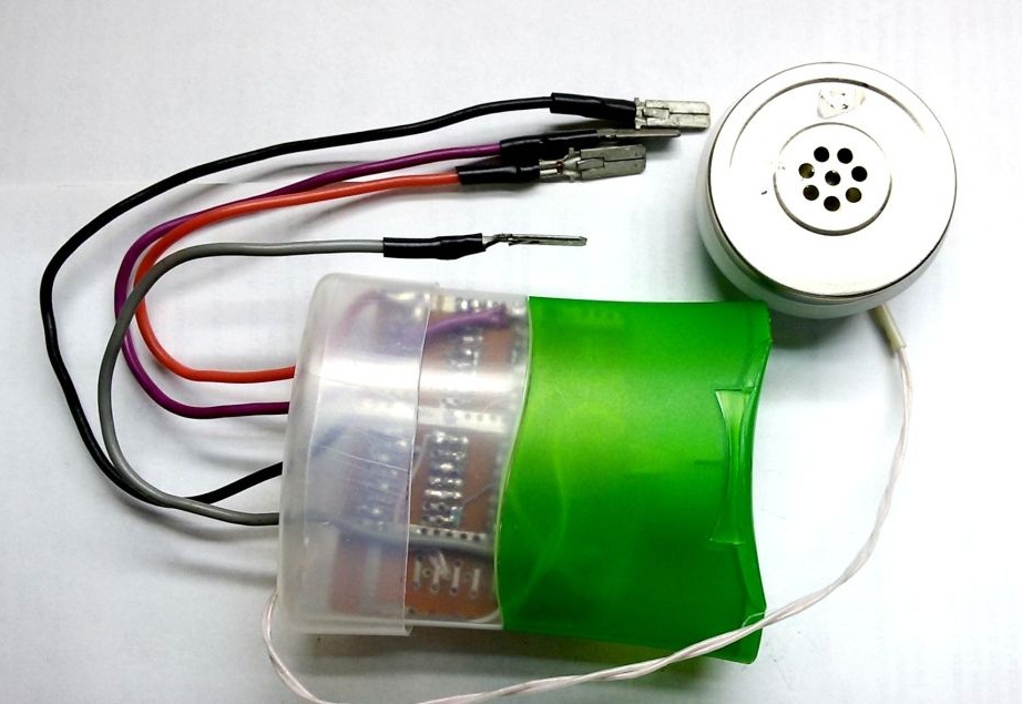
If the results are positive, we select the appropriate housing sizes to protect the detector circuitry from dust. In this case, a bottle of shampoo was used.
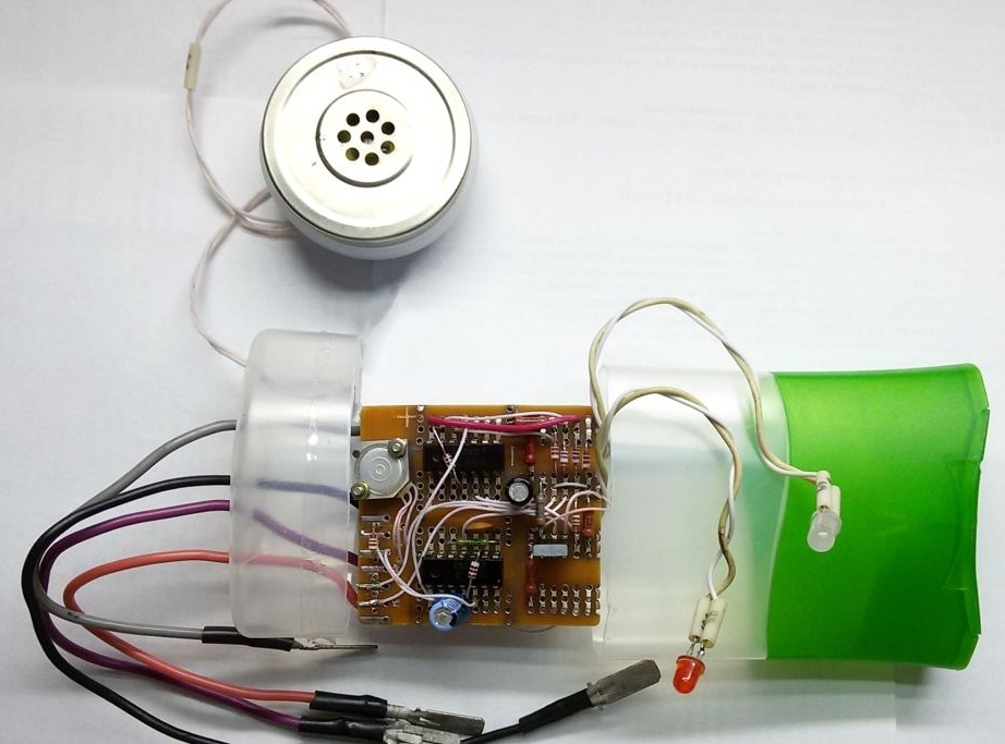
LED indicators are displayed on the front side.
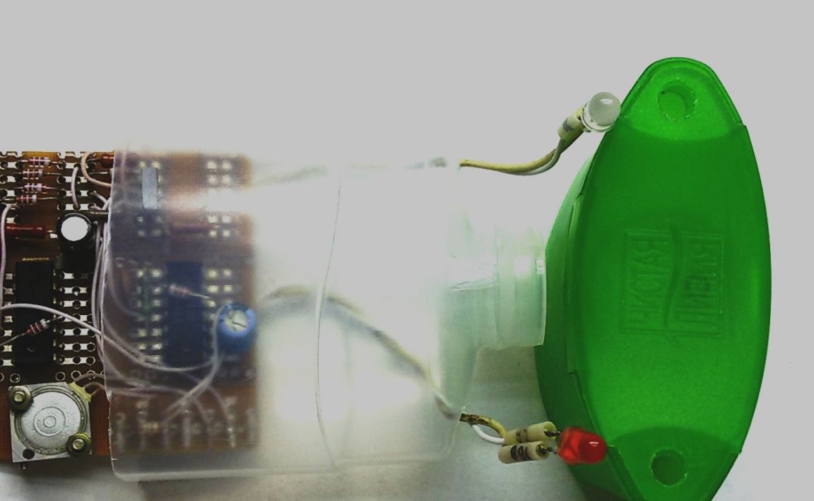
The sound head (in this case) is installed separately.
The design of the signaling device used low-power silicon diodes KD521, KD522 or others, with an allowable current of 100 mA and a voltage of at least 20 volts. It is not recommended to replace the K561LA7 chip with the K176LA7 series chip, because it may fail with a supply voltage of more than 12 V.