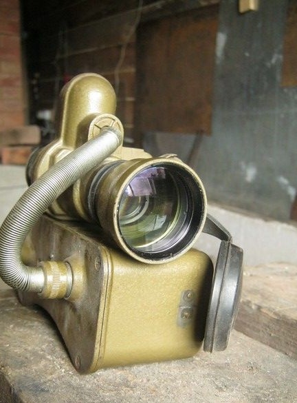
I got something like this on the occasion of such a night vision device. Relative garage when moving, dismantled and gave. PNV-57E is called. Of the first, probably, dad told me how in the army with such a thing on his head, he drove an APC at night. Years in the 60s probably.

What is he like? Let’s take a look on the Internet. Well, it is - for drivers of vehicles, all kinds, military. In principle, it is understandable by the lack of portable power, a headset and a set of cables. Yes, there is also PNV-57A, it differs significantly from "E" - it works only with IR illumination. In ours, it is quite possible to navigate in meager natural light, when, with the naked eye, practically, no dog is visible.
I only had a device with a converter, and the complete set is somewhat more extensive.
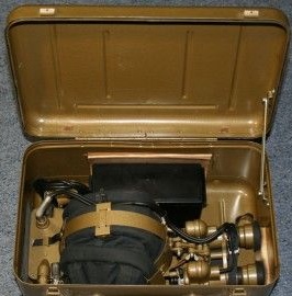
It also includes at least a helmet, like a tank one, on which all this economy is attached - binoculars in front of the eyes, a power supply on the back of the head, by the way, which is why it is so concave in shape. All this economy was dressed on his head and kept itself. Hands were free. I saw a schematic picture of how it should look like - a nightmare. Actually, the main purpose of the device became clear: to hide in it and sneak up to the adversary in the dark ... pat him on the shoulder, and when he turns around, after pausing after Stanislavsky, say ... boo.
We return, however, to the technical side.
What was used from the tool.
A set of tools for small radio installations, of course a soldering iron with accessories, a multimeter is useful. Something for drilling holes.
Power Supply.
The first thing to try is to power it from anything ... Power, as it turned out, the device is suitable for anything that can happen on a driving, crawling or flying technique, car, tank, armored personnel carrier, helicopter, from 12 to 30 volts. A cable with adapters was attached for connection, and in the power supply there was a stabilizer with a module, which, in the case of a higher voltage, included a relay with an additional quenching resistor.
Where OGN is a voltage limiter, STN is a voltage stabilizer, PPN is a voltage converter, V is a rectifier.
It operates in two voltage ranges 12 ... 15.5V and 24 ... 30.5V. It switches automatically. The output is 19.5kV. Not khukh-mukhra.
So, turn it on. There was a 12 volt power supply, oh! The converter was beeping, one channel of the “binoculars” was lit green. Already forward. We climb to see what does not glow in the left.
Binoculars.
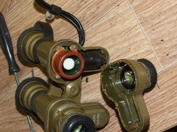
Wow, an ambush. Pieces of glass poured from the insides ... hello to the photomultiplier. We are curious what brought him to such a life, huh ...
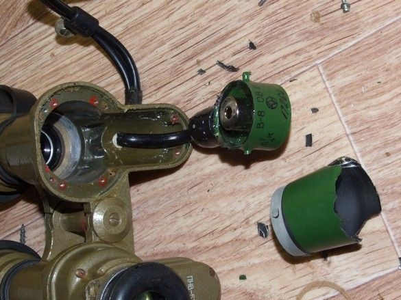
Such a brown clip made of textolite must be assumed, and the mounting screws are slightly twisted, literally a millimeter. The glass hung a little, it seems that the binoculars dropped or blurted out on something solid, where it was well fixed, the photomultiplier survived, and where it hung out to smithereens. Well, well, that’s what they say ... It’s curious that the whole device doesn’t seem to be repaired, from the factory, there all the notches for the screws, on top of the heads were filled with some kind of compound ... It seems like paraffin in half with TsIATIM or Vaseline. It does not seem to be smeared, but such as butter. And inside the power supplies at the joints. For tightness see. Well, it is clear that no one was picking. How OTC in the defense industry missed. They have it severe. And maybe they picked it and put it back on, but it doesn’t matter. One eye still doesn't work. I was curious on the Internet, it turns out you can still get such a photomultiplier, but it was a pity to give 1500r to bring the toy to mind.
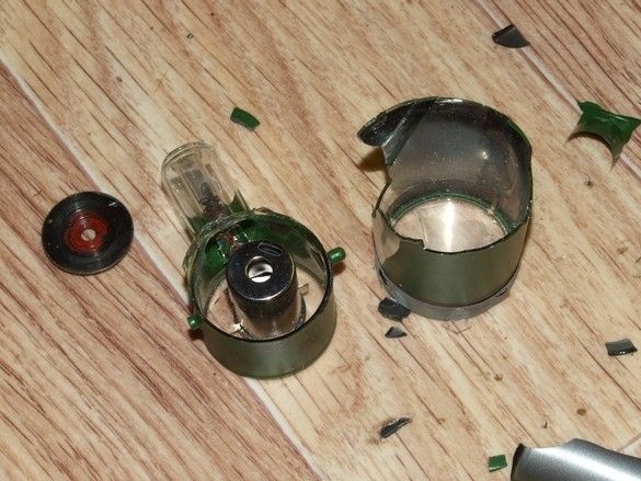
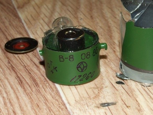
Then he figured out how to give the product some completeness. I took apart the binoculars in half, since it turned out to be a simple and inoperative channel, in a box in the attic, in case the image intensifier tube falls into place of the broken one.
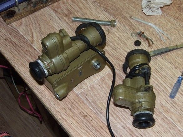
High-voltage wires had to be redone. As soon as there was only one eye left, it was decided to place and carry the transducer nearby, therefore, the wires would have to be, one to be disconnected, the other remaining, to be substantially shortened.
We disassemble the plug-in connection of high-voltage wires to the converter, along with the converter itself.
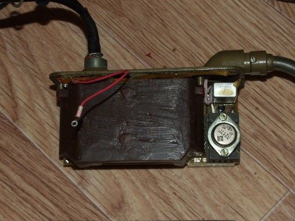
Here, at the bottom of the casing, the circuit is basic, so as not to run, not to look.
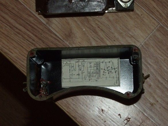
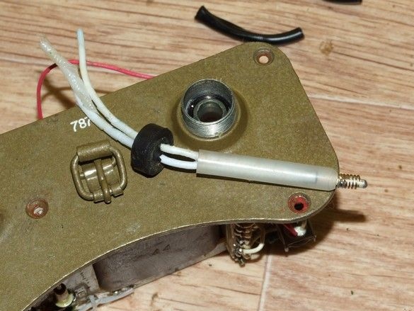
A special applause deserves the construct of a high-voltage converter. Here, evaluate in the photo how the cable was connected so that the kilovolts do not "sew" onto the case (and with regular use, the power supply unit hangs on the back of the head and wires all over the head). And the multiplier is cool to mount, a separate flooded module is jammed onto the transformer and only contacts through the spring.
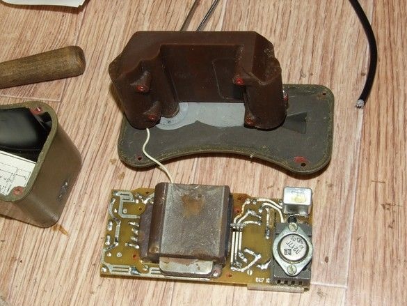
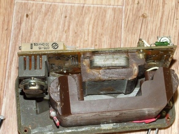
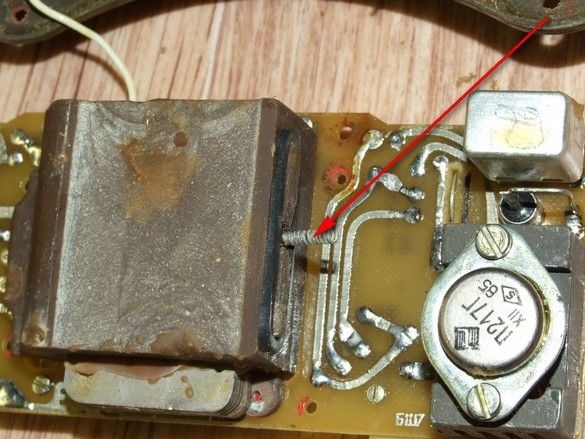
Maintainability, again at the height. Replacing a critical part in terms of reliability is a matter of five minutes with one screwdriver.
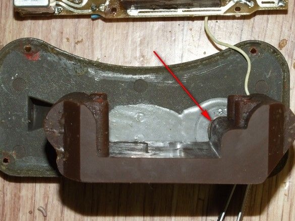
The socket for the “probe” with high-voltage wires is made integrally with the case of the multiplier. The angle in the photo indicated by the arrow is what it is. Outside, through the hole, a plug is inserted into it. Contact deep in the hull.

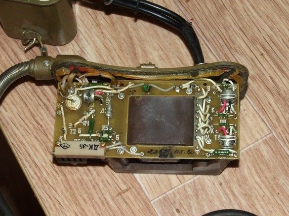
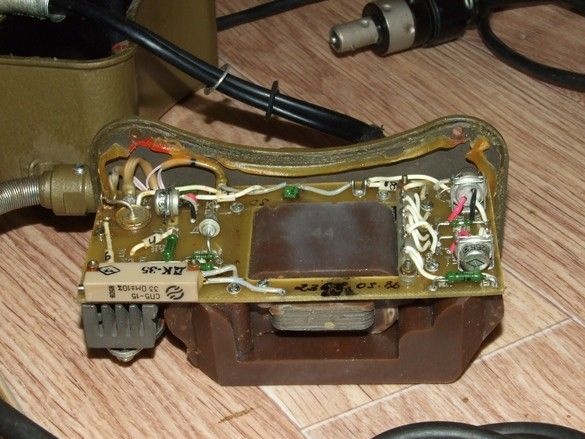
Pay attention to isolation of conclusions and fastening of elements. Everything is attached to death, no vibration is terrible. As usual, three layers of urethane varnish. The high-voltage wire to the “binoculars” has insulation from the layers of the fluoroplastic tape, on top of which is a rubber sheath. Extremely flexible - convenient.
Soooo, now with an external power supply. It is somehow inconvenient to supply power from the network adapter, it is tied to the outlet. What can be done.
Hmm, curious, so what is in our diagram ...
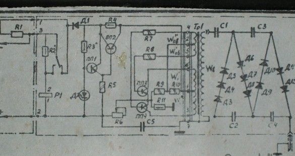
Well, the input voltage switch, then the classic compensation stabilizer with a transistor on the radiator ... a reference zener diode, how much, you say? Oh, at 9 volts, well, here’s the solution - the elements of the stabilizer, plus the relay, are deleted, and since they occupy a fair amount of space and in one corner, the pocket for the battery and the tiny toggle switch is released.
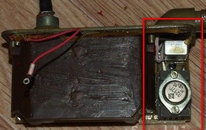
In the diagram, this is -
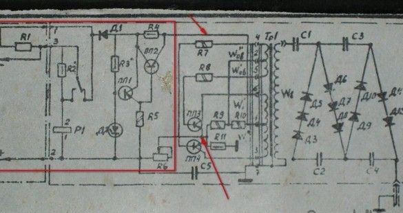
The arrows indicate the points where the Krona battery is connected. 9 volts. In the gap of the positive wire we put the power switch. First things first, I bit inside the wires from the external power cable and unscrewed the cable itself.All elements marked with a rectangle neatly evaporated. An aluminum radiator, trimmer resistor, all unnecessary rivets and fasteners are also removed. Elements on the board are signed, it’s convenient to navigate.
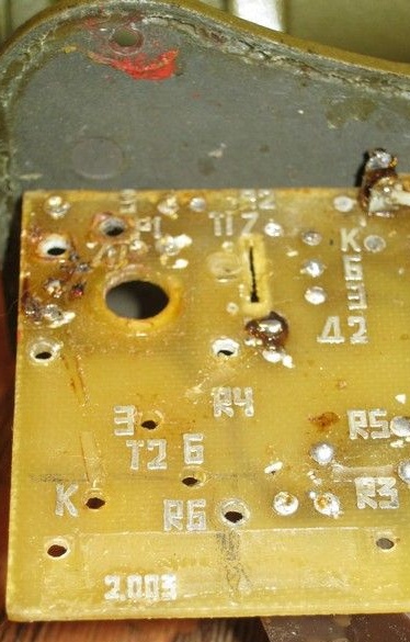
The angle in which there was a switch and a stabilizer becomes empty, only the tracks of the printed circuit board remain. They will not interfere.
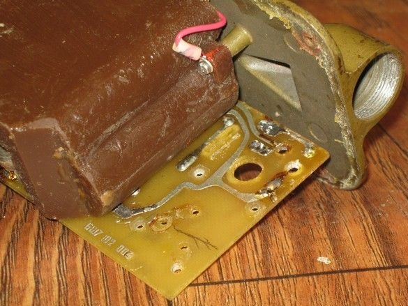
Then, turning the power supply case in one way and another, I found out where it would be convenient to place the power on switch so that it would fit and switch on inside. Scheduled, drilled.
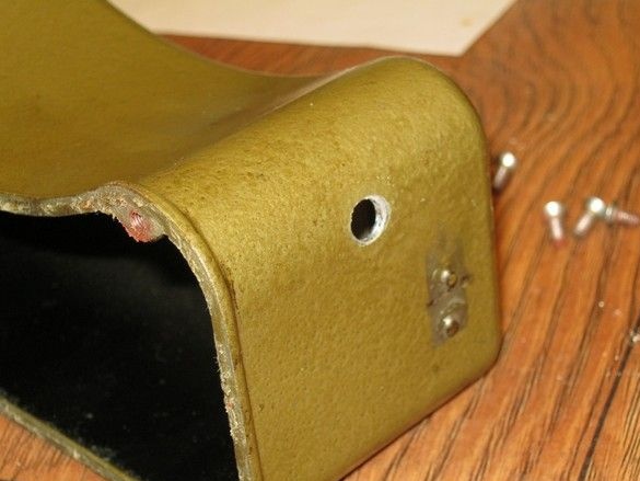
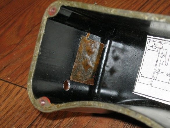
The specific Krona battery block was picked out from the same discharged battery. The contacts are soldered segments of the installation wire. The plastic block and solder should be a fairly powerful, well-heated soldering iron. Otherwise, the risk of melting the insulator is great and the contacts will not fasten on the battery.
The battery with the switch is connected at two points (see the diagram above), one of them is marked by an arrow in the photo below.
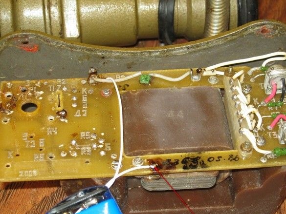
To access the second, I had to disassemble the power supply - disconnect the high-voltage cable from the outside, remove the multiplier and transformer of the converter. It should once again pay tribute to the designer - maintainability at a height.
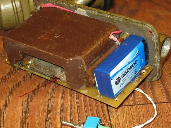
We see how conveniently the battery is located. It remains to wash the remaining flux with alcohol or an alcohol-gasoline mixture and can be collected. The switch is in place. Dressed and fixed casing.
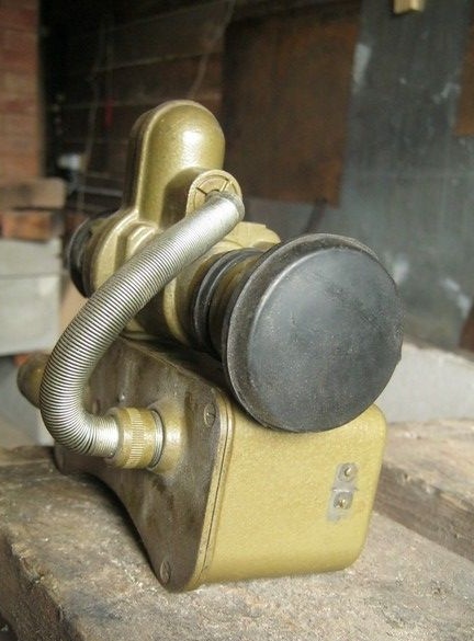

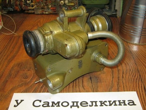
It remains to make and attach a nameplate, hmm ... "All-seeing eye" or "Looking into the darkness." The latter is certainly gothic.
Yes, here's another, there were several other photos, a picture through such a device. To explore the possibilities.

View through a window to an unlit street. Several lights are visible, but nothing more.
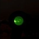
View of the same place through the working PNV-57E.
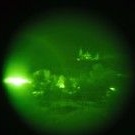
A little bigger. It can be seen that the resolution is quite satisfactory. You can confidently navigate.


