» Electronics » Power supplies »Adjustable power supply - very simple, even a schoolboy can do. In detail

An adjustable power supply is very simple, even a schoolboy can do. In detail

And again, I am glad to welcome You Dear master friends!


Today, I want to talk with you about old and seemingly worthless dusting in the corner of an apartment or the garagecompleting your old computer. In particular, about an old computer power supply unit, not working people in your eyes, but still issuing its own 12V DC voltage.

The computer power supply, I can say with great confidence, is the perfect device for any master. From a computer power supply, you can make a good regulated source of constant voltage.

Today, the price of a laboratory power supply reaches ten thousand rubles. But, there is a good option, just remake the computer power supply into an adjustable laboratory power supply. Of course, it will not be so accurate, but it is quite suitable for the work of a home master. And it will cost YOU about 350-400 rubles. Having spent one and a half to two hours of your time, you will get a power supply for: 3.3 V, 5 V and an adjustable voltage of 12-35 Volts, a pretty decent power.

Adjustable power supplies are good in that they enable the master, the master, and simply the consumer, to regulate the output voltage. Such power supplies can be used for various purposes, for example: for checking incandescent lamps, LEDs, charging batteries and for powering various electrical and electronic devices in your workshop.

And to summarize, a power supply with voltage regulation at this modern stage is an absolutely necessary thing for any real man, with his hands growing not from n @ py. This simple device, due to its technical properties, can easily convert the voltage and current available in your electrical network to a level that is suitable for the consumption of a particular electronic device.

I want to offer a budget option for an adjustable power supply, as noted above, for accessories, it will cost you 350-400 rubles, agree 400 rubles is much less than 10 thousand.

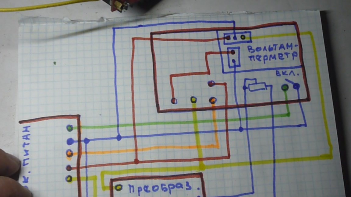
This power supply, I’m sure, can be done by any novice master who has at least the idea that the current runs through the wires. In the article I will describe in detail the manufacturing process of the power supply, and if you are interested in this device, I will conduct detailed installation of all the wires and systems of this device in the video clip of the instruction.
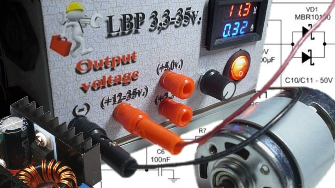
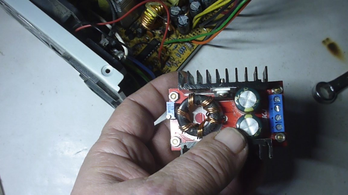
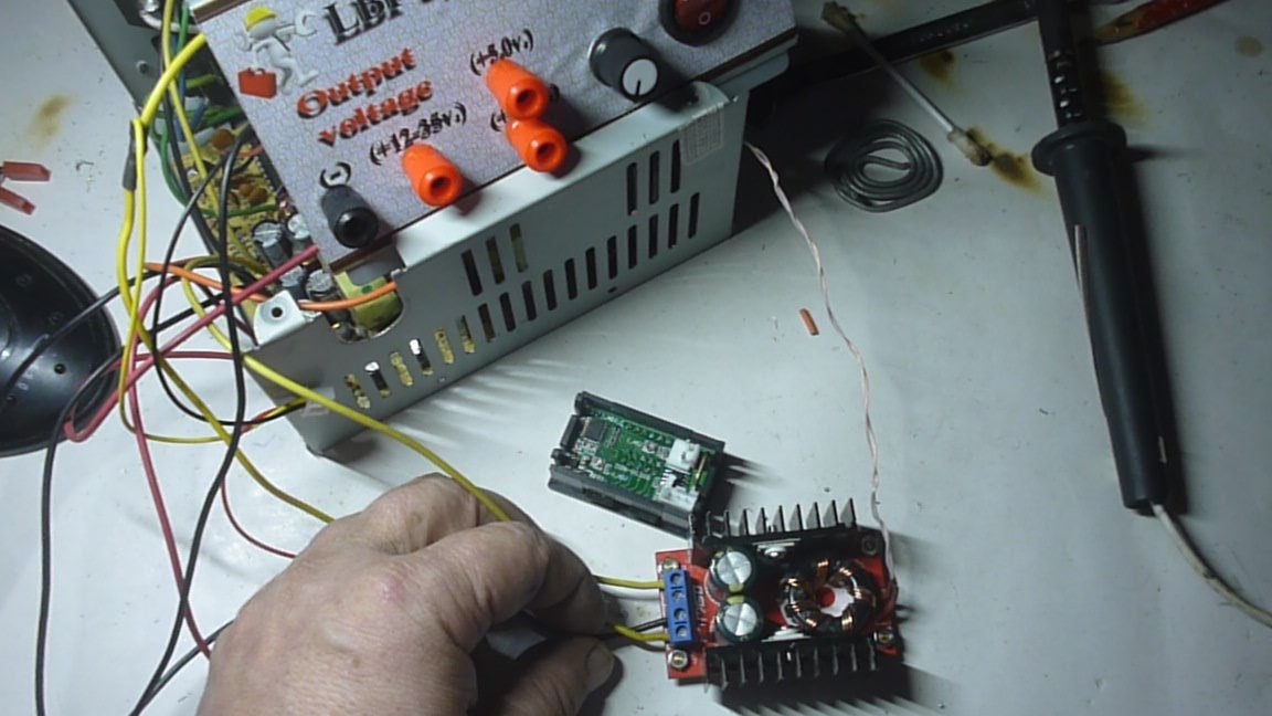
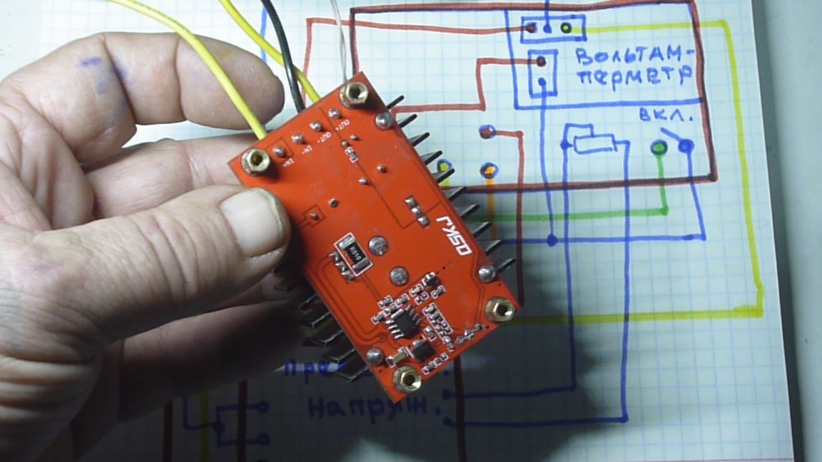
The idea of ​​an adjustable power supply is very simple. Now in Chinese online stores appeared DC / DC converters. In our case, the boost converter with the declared power of 150 watts is taken as the basis. (Our Chinese friends, of course, as always overestimate these parameters, but there are probably 100 watts.), With a fixed power supply from 10 to 30V and an adjustable output voltage from 12 to 35V. Links to Aliexpress where you can purchase this converter and accessories for our power supply are available in the video clip.

Having powered this converter from our computer power supply unit with 12 volts of constant voltage, at the output we get an adjustable voltage of 12-35V. Also in the computer power supply there are fixed voltages 3.3V and 5V. We will also remove them on our device.

It has already become a tradition in our articles to talk a little about safety precautions. My advice to you: never check the availability of electricity in your tongue and you will have a wonderful Hollywood smile and a good, easily digestible speech. Do not stick your arms and legs in those places where the dog does not stick its tail, and you will still dance the gypsy and play the piano.
For safety, basically everything.

Getting to the production homemade.

In the beginning, for those who like to watch more than read, video clip instructions on how to make an adjustable power supply from an old computer unit:

Video clip of manufacturing a power supply:


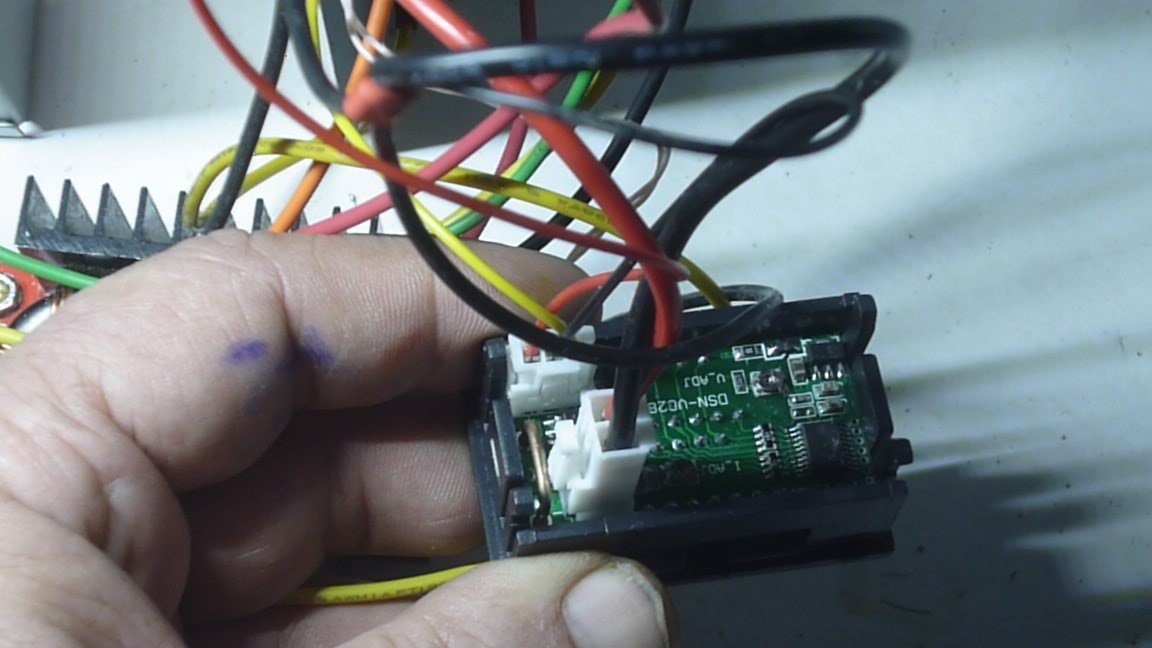
Video clip connecting a multimeter DSN-VC288

100V and 10A (a detailed description of the ladies in a separate article):


Tools that are useful in the manufacture of our device:


1. Soldering iron.
2. Screwdrivers.
3. Drilling machine or drill.
4. Drills.
5. File or file.
5. Emery cloth.
6. Stationery knife.
7. Wrenches.
8. Measuring tool, at least a ruler.
9. Descriptive tool, pencil.
10. Kerner.
11. Pliers or pliers.
12. Cutting machine (grinder) with a cutting wheel and grinding.

Consumables Required:


1. Solder.
2. Soldering acid.
3. Bolts and nuts.
4. Installation wires.
5. Step-up voltage converter.
6. Voltammeter 100V, 10A.
7. Plugs, connectors and other trifles.
8. The switch.
9. Variable resistor.
10. Heat shrink tubes.

The procedure for manufacturing an adjustable power supply:


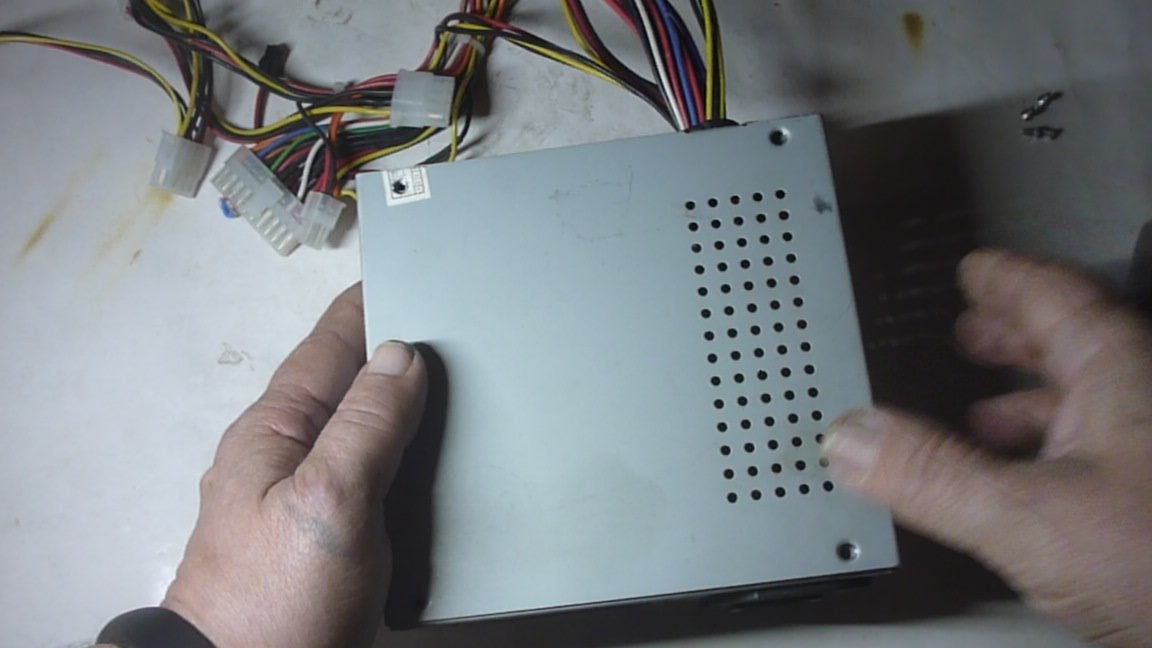
1. Find an old, working computer power supply.
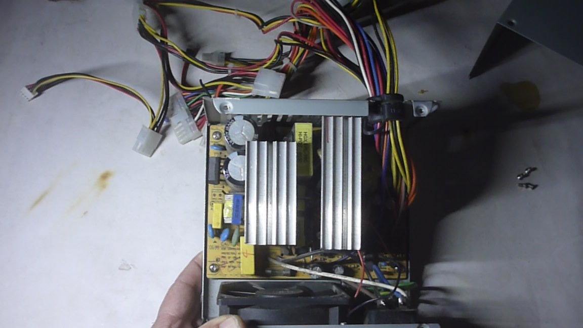
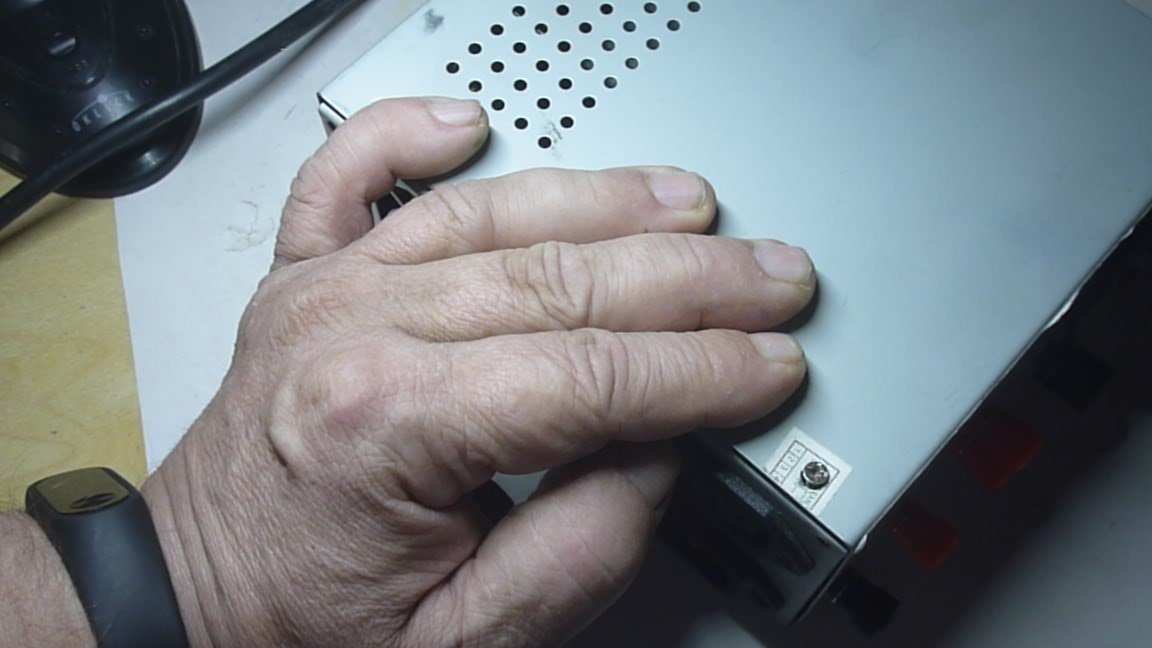
2. Open thoroughly but gently clean from accumulated dust and dirt.
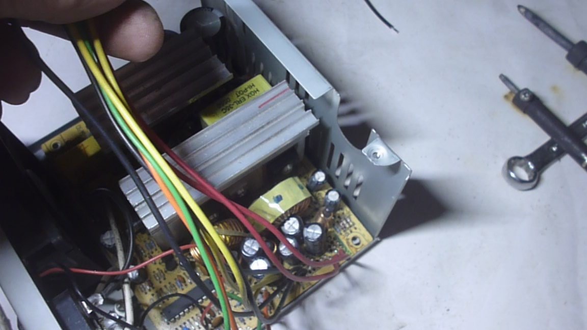
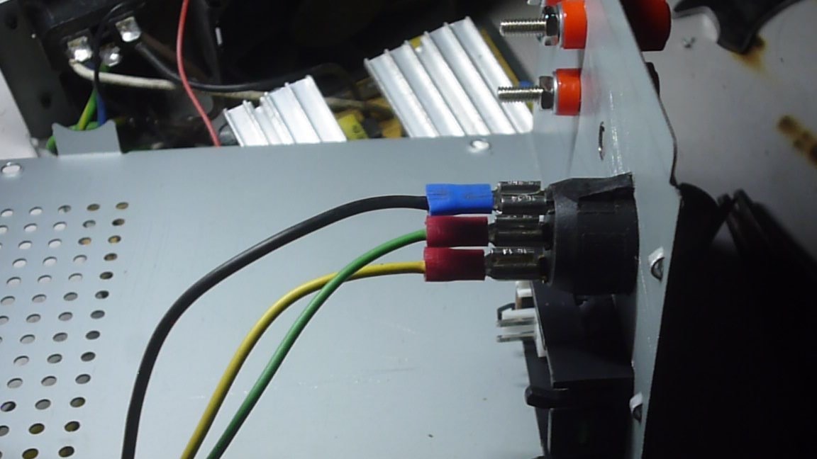
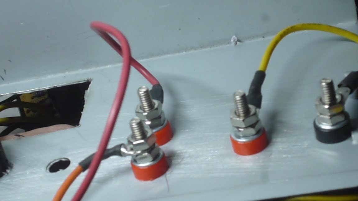
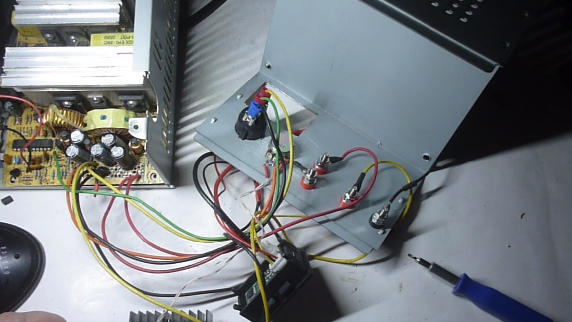
3. To remove excess wires from the bundle, leave black minus power, yellow 12V plus, orange 3.3V plus, red 5V plus, and green to turn on the power supply.
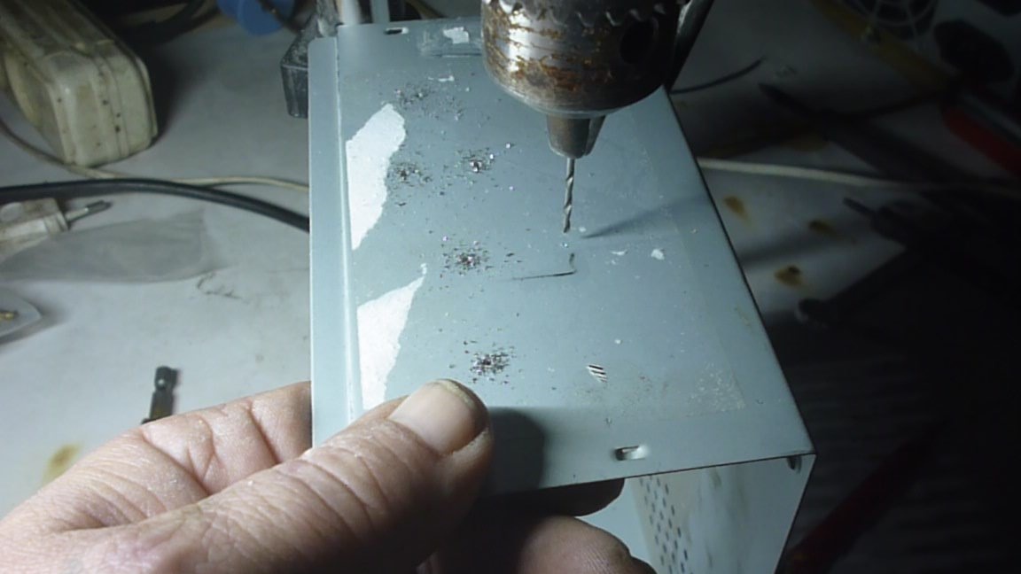
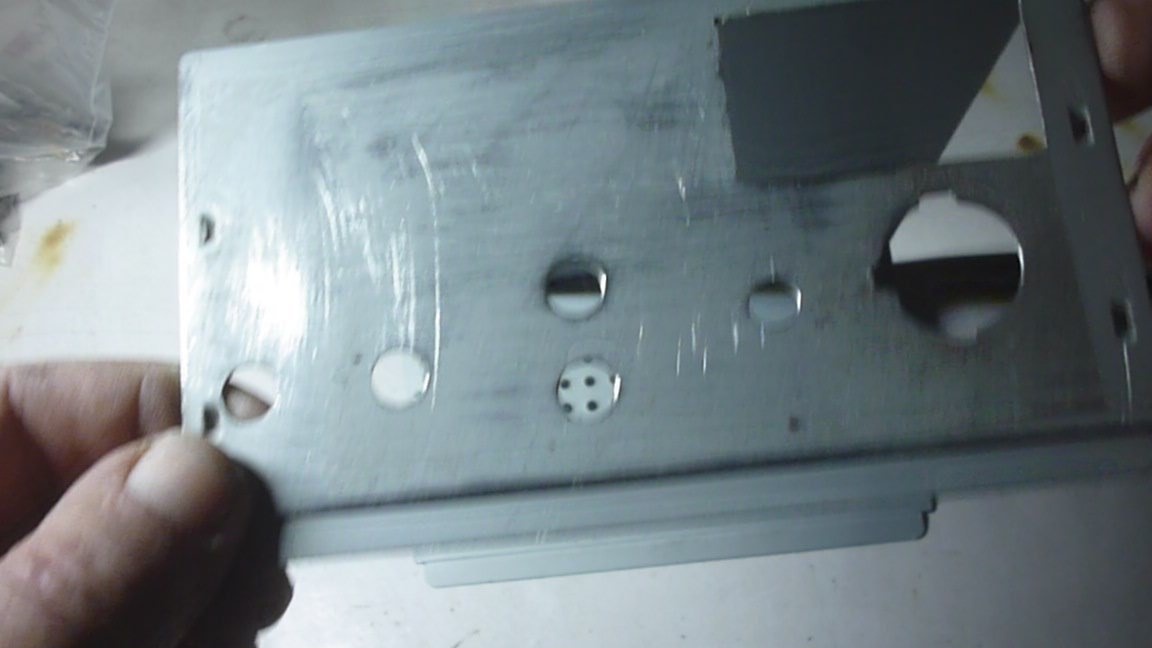
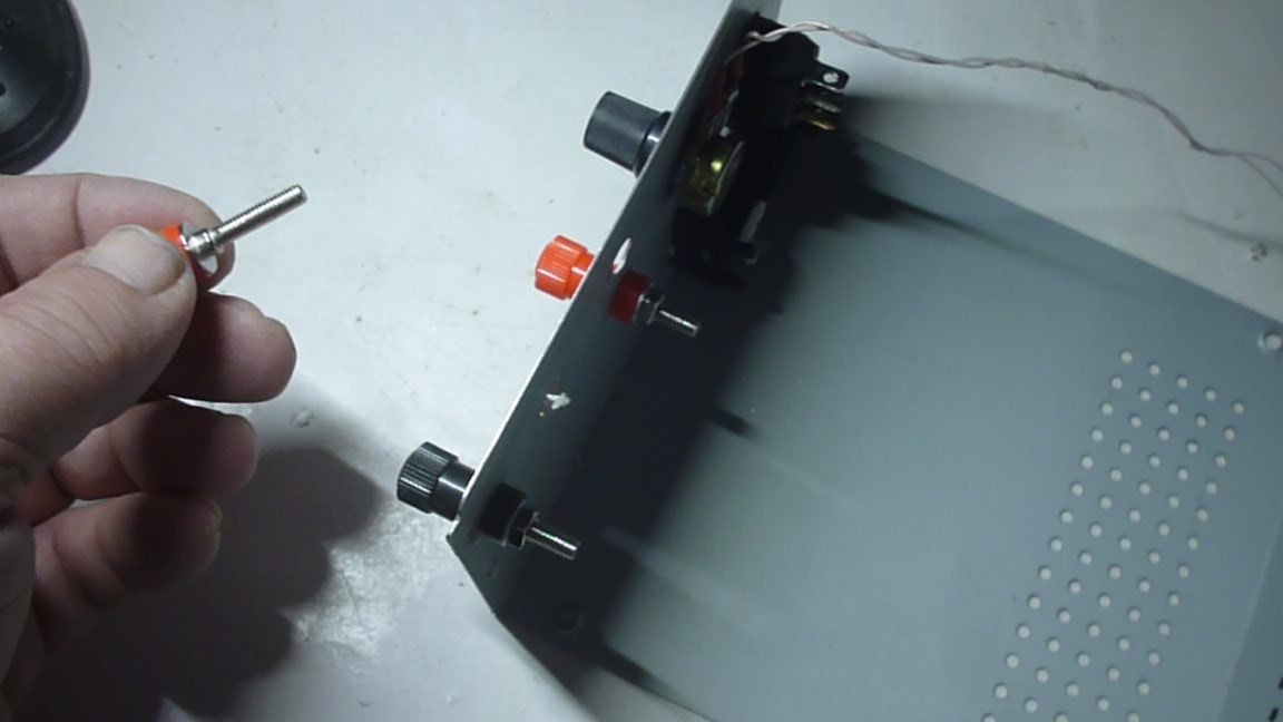
4. On the front panel of the power supply, drill and drill holes for mounting control devices, control knobs and voltage relieving connectors from our device.
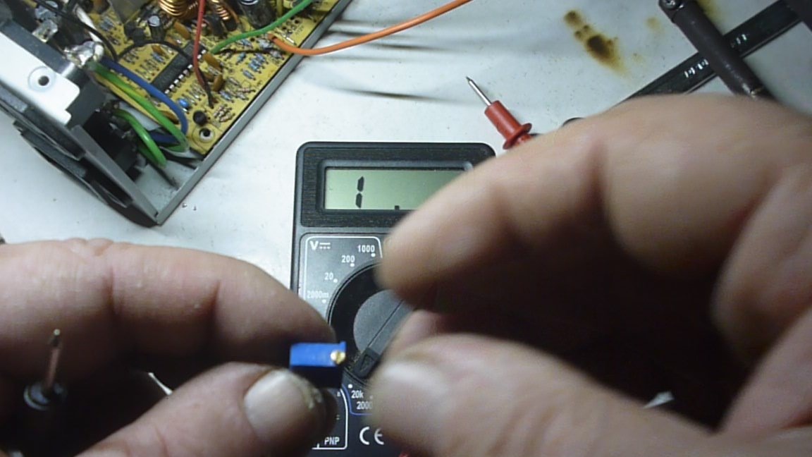
5. Solder the tuning resistor from the step-up voltage converter, solder a 10 kΩ variable resistor in its place.
6. Solder the wires of the power supply unit, it is shown in detail in the video clip, do not panic, everything is very simple, the main problem is not to burn your fingers with a soldering iron :-).
7. On the front panel, place and secure the multimeter, control knob, switch and voltage relieving connectors.
8. Connect the prepared wires to the multimeter, control knob, switch and relays.
9. Place and raise the step-up voltage converter connected to the power supply unit and fix it in our power supply unit. The full-time position is shown in the video.
10. Assemble the case of the resulting power supply.
11. Connect the power supply to the 220V network.
12. Click on the switch to turn on the device.
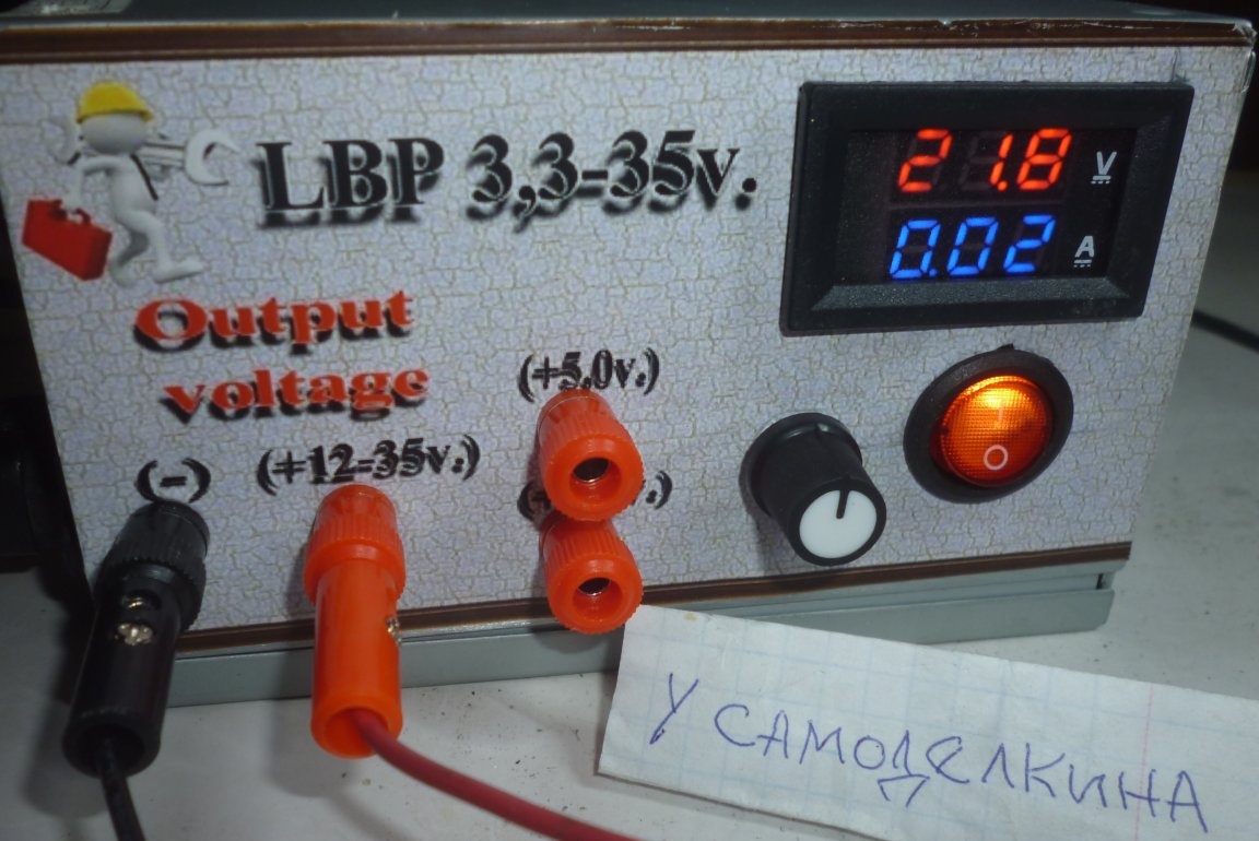
13. A voltage should be displayed on the multimeter.
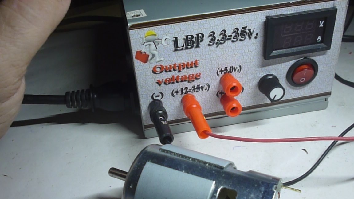
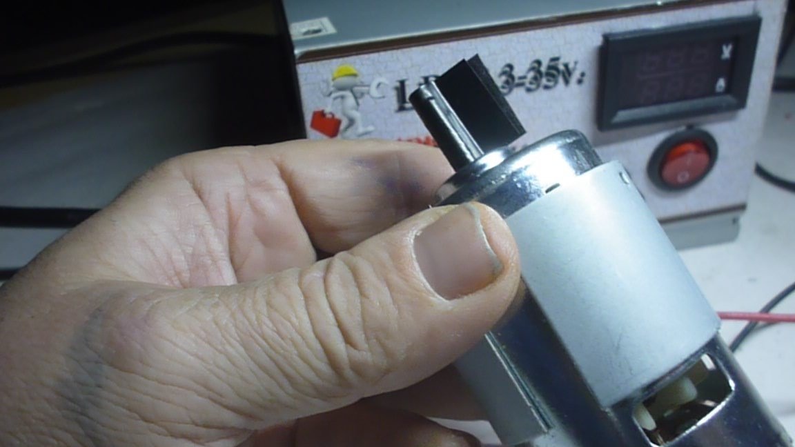
14. Set up and test the regulated power supply under load.

Technical analysis:


Pros:

1. budget costs for component structures.
2.sufficient compactness.
3. Easy to manufacture.
4. Easy operation.

Minuses:

1. Insufficient accuracy of the device, from 10 mA.
2. The voltage is adjustable from 12V. 3.3 and 5V fixed voltage. But we are working on it.


That's all for today! Good luck to you!
5.2
5.8
6.2

Add a comment

    • smilesmilesxaxaokdontknowyahoonea
      bossscratchfoolyesyes-yesaggressivesecret
      sorrydancedance2dance3pardonhelpdrinks
      stopfriendsgoodgoodgoodwhistleswoontongue
      smokeclappingcraydeclarederisivedon-t_mentiondownload
      heatirefullaugh1mdameetingmoskingnegative
      not_ipopcornpunishreadscarescaressearch
      tauntthank_youthisto_clueumnikacuteagree
      badbeeeblack_eyeblum3blushboastboredom
      censoredpleasantrysecret2threatenvictoryyusun_bespectacled
      shokrespektlolprevedwelcomekrutoyya_za
      ya_dobryihelperne_huliganne_othodifludbanclose
124 commentary
Identical and symmetrical are not the same thing, although the first one is more to my taste. (at one time he worked a lot with B5-46, -47). Nowhere is it said, but for some reason it came to me as if it was a question of one common rectifier. scratch
Ivan_Pokhmelev, You got ahead of me about two identical channels. They say the same thoughts happen in fool ... smart people. I wanted to offer at night, but fell asleep. At my work, about 30 years ago, there was such a power supply unit manufactured by MEPhI. So, he had 2 separate adjustable channels from 0 to 15 V. And we connected them in every way. And they got either two polar + -15V, or one polar 30V, or fed 2 separate devices.

That's what kind of power supply you need to blind. I WANT SUCH xaxa Here is the topic for homemade.
That's it, that "quasi". ;) It can be done differently: two completely identical modules, powered from separate transformer windings. We connect the minus of the first to the pole of the second - this will be the midpoint. And you can connect, for example, the minuses of both sources or the pros. In short, as it should - and connect. So normal two-channel LBPs do - with channels isolated from each other.
I agree, in terms of circuitry. Functionally, well, almost symmetrical. No wonder quasi. smile
I said "symmetrical." You get the OE output in one shoulder, and OK in the other.
Well, why?

According to the 1st picture, of course, it’s easier, the quasicomplete pair of the 2nd is a little more complicated.
That's just the point, which is problematic nea make a symmetrical bipolar PSU specifically with KT827 in both shoulders.
Anonimus
Why is 827 bad? normal transistors, though 825 and 827 will be more canonical.
Author
Quote: Guest Alexander
two DC-DC modules. 12v

I’m just waiting with aliexpress, as soon as I arrive I will collect almost as you indicated, but almost so.
Guest Alexander
Have a nice day! The LBP was assembled similarly, only in the output stage can part of the parts related to 5 and 3 volts be discarded. Activate the 12v output. On AliExpress we buy two DC-DC modules. 12v we feed on the first module XL4015 (boost) adjusted almost on MAX. On its output, sequentially, put XL4005 (lowering) We change its potentiometer to the usual one, as in the article, and display it on the panel. In this way we can adjust the voltage from 32v to 1v on a smooth scale. Depending on the connection of the potentiometer contacts, the adjustment changes from smaller to larger. Current no more than 5 amperes. (Long-term 3 amperes) If necessary, more power, you can use the XL-4016 modules. These are 8 and 10 Ampere (150-200 watts) modules. Install them instead of the cooler. I adapted a small cooler from the video card for cooling. (put on the side) Voltammeter as described. I have been using this power supply for about 5 years, and I have collected 3 of these friends and everyone is happy. There are even 300 wad modules, but they are expensive. 5 amperes - 50-70 rub. 8 amp-150rub. 10 ampere-220 rub.
Quote: Pronin
An automatic fire extinguishing station should also be placed nearby, since the reliability of such converters is low.

yeah unreliable, also burning .... scratch
They have been working in computers for years and no one has kept a fire extinguisher close by, although it happens that they die, there is nothing eternal.
Pronin , I also noticed that this, suddenly, another power supply caused 9 thousand views. Really all the students rushed to collect it? xaxa xaxa xaxa
2Dovakin
I once did this, 3 ... 35 V, a step switch for current limitation of 0.1 ... 2 A, an output to the KT808 (one channel in a quasi-complementary scheme), and later redid it to the KT818 ... 819. Bulky, bipolarity is rarely needed, in short, I gave it to the guys on the radio circle.
And about ... There is a complementary to KT827-th - KT825-th, and even import in bulk.
Author
Quote: Pronin
they are unreliable

Buy ready-made at the store ...
Dovakin
And I want bipolar And so that transistors are used as a regulatorditch voltage KT827. Weak?
In both shoulders CT 827? Want is not harmful! nea
"- it’s very simple, even a schoolboy can do it" and immediately 9 thousand views. declare
Faced with these "old computer power supplies." Often they do not give out the required output. parameters (voltage and current). And they are unreliable, maybe it's impulses. Add another impulse (boosting !!) and charge the car battery (12V) for 8 hours. Then you also need to put an automatic fire extinguishing station nearby, since the reliability of such converters is low.
Dovakin
Well yes! Everything you need is ready to have or to buy from Ali. And I want bipolar from zero to forty volts and not pulsed, but based on a toroidal transformer, two rectifier blocks with batteries of filtering capacitors. And so that transistors are used as voltage regulators KT827. Weak?
Author
Quote: Lyublyumyaso
which converter

Lyublyumyaso
And which converter was installed?
Author
Quote: Dzugkoyev astemir
is it possible

Can
Dzugkoyev astemir
is it possible to connect a step-up adjustable converter power and amperage to both power supplies from a computer?
Recently, I needed to power the car radio, connected it to a computer PSU, everything works. I removed all the extra wires, the PSU stopped starting! I looked carefully - from the 13th pin (+ 3.3V) of the connector, a thin wiring (not on all PSUs, sometimes orange, sometimes brown) returns to the PSU board at the point marked + 3.3V Seh. Threw a jumper directly on the board - it worked! yes
Author
Quote: EandV
Also, as an option, set the boost module for example 30V, and then connect another step-down

You are reading my mind, I'm already waiting from China for a 400 watts boost module. 10-60 volts at the output. I think to put two modules through switching. I still select a voltage-reducing from 1.2 to 10 volts, today I looked at XL4016 on aliexpress and ebay, in principle, what I need, I'm inclined to it, but I'm still thinking about looking for options. Decent price plug. I’ll assemble the device, lay it out. AND SO, YOU HAVE GIVEN EXACTLY IN A BUTTERFLY! :-)))
Good afternoon! I myself am the owner of a pulsed "lab" from the finished modules. Only with me it is made on the XL4016 step-down module. As a power source - a ready-made factory unit for 24V 5A. Of the advantages: a range of adjustment from zero to 24V (the most popular voltage I personally have in the range of 5-15V) + current regulation with stabilization (which allows you to use the unit as a charger). I’m all of this to the fact that it would be nice to add the above module with a separate line to your block. As an option, set the boost module for example 30V, and then connect another step-down and eventually get 0-30V adjustment + current regulation. But a double conversion (first raising, then lowering) is already a bit of a perversion, to be honest.

We advise you to read:

Hand it for the smartphone ...