
Hello friends the inhabitants of our site! In this article I will try to describe and show as much as possible the assembly of a kit for self-assembly, the so-called kit kit. This kit for self-assembly can be purchased in the aliexpress online store by clicking on this or the link at the end of the article. Namely in this article we will collect car on the radio control. Even a child can assemble this kit, and it is even better to collect this constructor together with the children; moreover, it will be safer for the child. It will be very interesting for the child to assemble his first car. This kit kit is different from many other Chinese kit kits in its simplicity and lack of small parts. This kit can be used as a methodical designer for schoolchildren in schools so that children understand the simplest principle of electrical appliances.
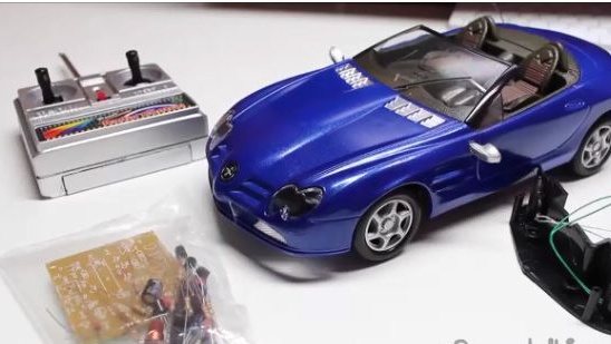
Included in the kit of this constructor.
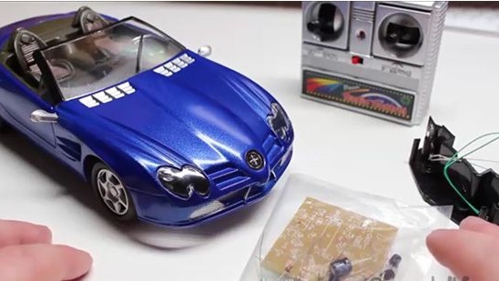
1- Radio remote control.
2- A bag with many elements.
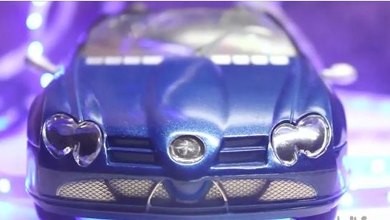
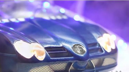
3- Front optics.
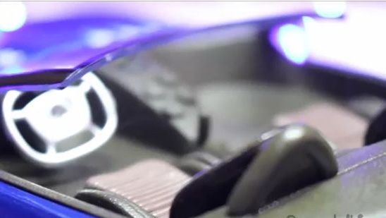
4- The body of the machine itself with a passenger compartment and transparent plastic windows.
5- Car frame with electric motors.
6- Main circuit board.
7- Two electric motors.
8- Battery connector.
9- Switch.
10- Rubber tires.
Assembling a car for radio control:
1- Well, let’s not take the time and start assembling the car model right now.
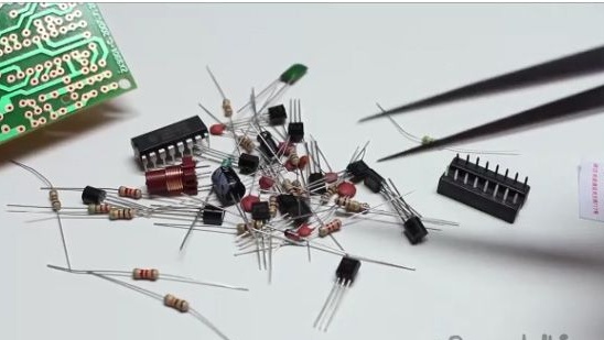
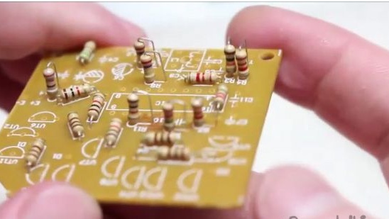
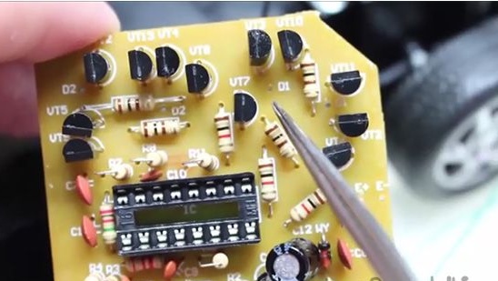
2- Naturally, the assembly of this designer will need to start with the soldering of the printed circuit board. Let's start, we will regret as usual with the installation of resistors on a printed circuit board. The biggest difficulty is that the resistors do not have their face values, so it would be a dream to recognize the name of the resistors on their own. You can find out the resistor count in the old fashioned way with a multimeter, or with the help of a mobile application that can be downloaded from the mobile app store by typing in the search engine “find out the resistor count”

3- I sorted all the resistors, and I advise you to do it as it is shown in the photo below, you need to do this in order not to mix up the values during assembly.
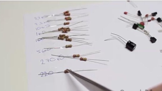
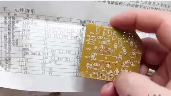
4- The values of all the inscriptions on the printed circuit board can be seen on the diagram that comes with the designer. For example, 100 ohm resistors will be installed in places R15, R16, R17, R18. And in the same way we will install all subsequent elements on a printed circuit board.
5- Install the resistors in their places. It should be understood that some resistors from the close distance of the holes in the printed circuit board will need to be installed vertically relative to the printed circuit board.
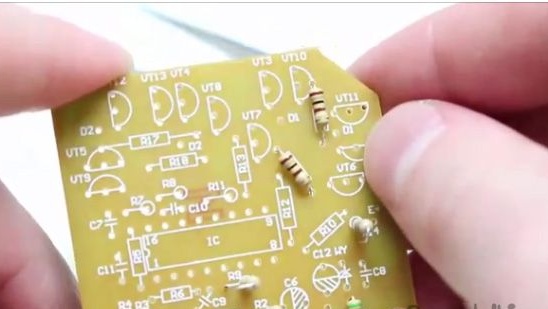
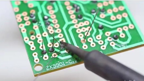
6- Solder the newly installed resistors and bite off the extra legs.
7- This is what the printed circuit board should look like at this stage (see photo below).

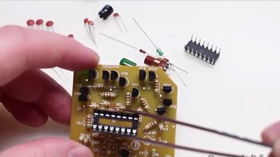
8- After which we proceed to the installation of transistors. The main thing is not to mix them up. The kit includes five s9014 transistors, four ss8050 transistors and four 8550 transistors. And according to this scheme, we install and solder them to the printed circuit board.
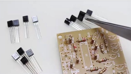
9- At this stage, the printed circuit board should look something like this, as shown in the photo below.
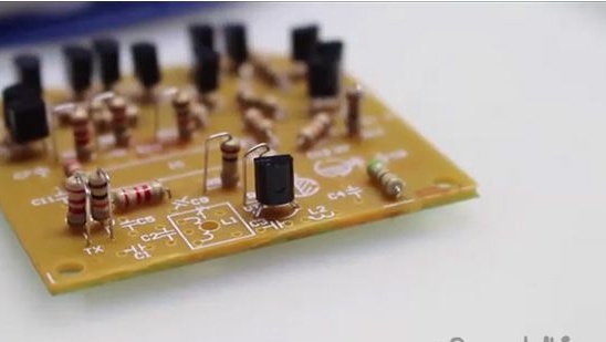
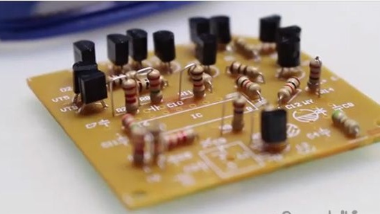
10- Transistors are installed. It remains to install several polar non-polar capacitors, an inductor, which acts as an antenna, a diode, inductance, a shoe under the chip and, accordingly, the chip itself.

11- We install all the above-mentioned elements in their places according to the scheme, not forgetting that the block for the microcircuit should be installed according to the key that is printed on the circuit board and marked on the block itself.
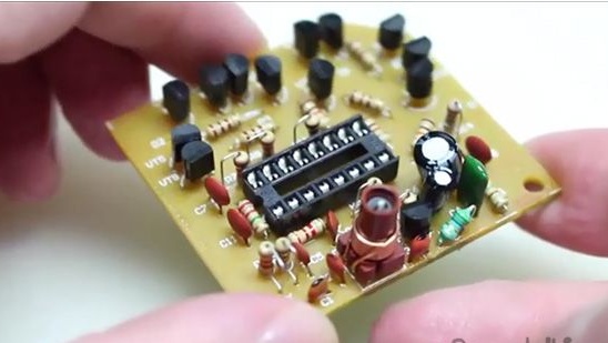
12- Something like this should work after installing the above elements.
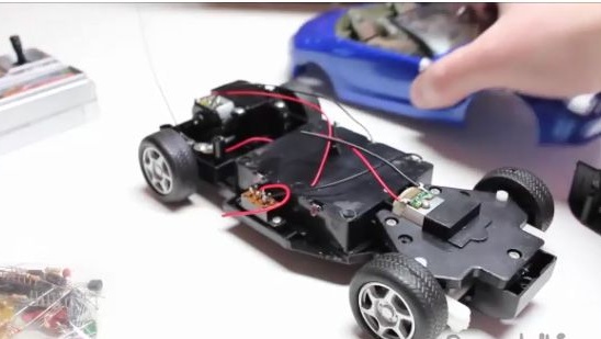
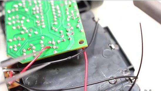
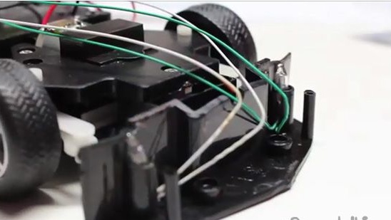
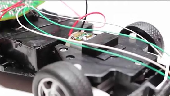
13- Then we will deal with the car’s chassis itself. What we have, and we have the following. Namely, two electric motors, one of which acts as a rotary mechanism, and the second electric motor, respectively, is responsible for moving the car forward and backward. There are also positive and negative contacts from the batteries and the switch. And from out of nowhere a small red wire sticks out, which is an antenna. And also we have front LED optics of the car, from which two wires from each LED come out.
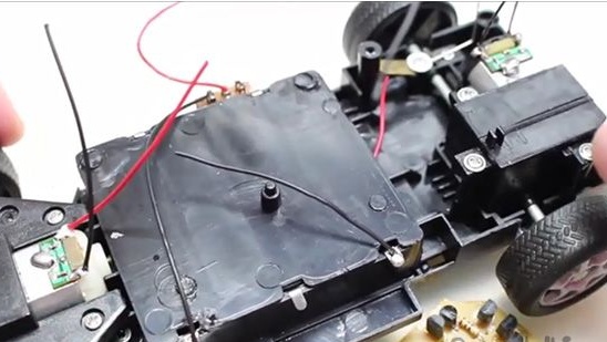
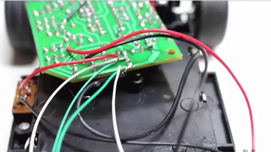
14- Now we begin to connect the car wiring to the printed circuit board. In the instructions, of course, everything is in Chinese and it’s really difficult to figure it out, but I figured out where to solder it by typing. So we remember, to the contacts d1 we solder the electric motor of the front axis, to the contacts d2 the electric motor of the rear axle, we solder the optics to the same place and solder the power to the circuit board from the batteries.
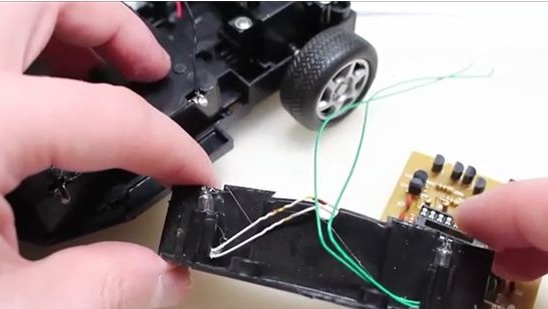
15- Solder.
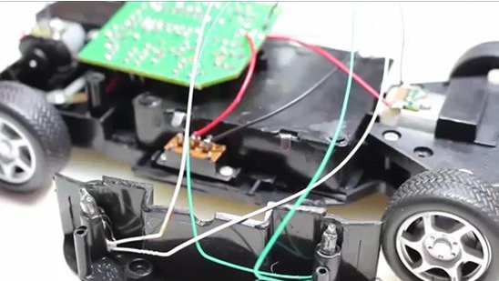
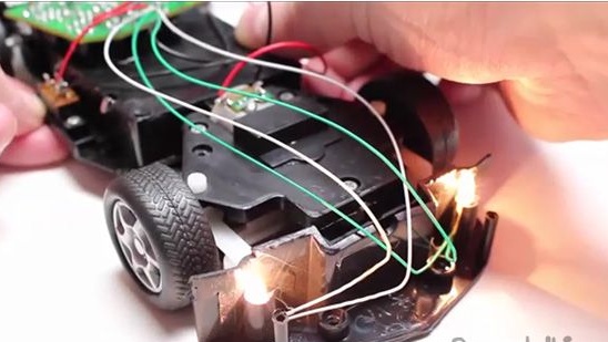
16- Ready. We insert the batteries into the remote control and install the batteries into the newly assembled car itself.
Conclusion:
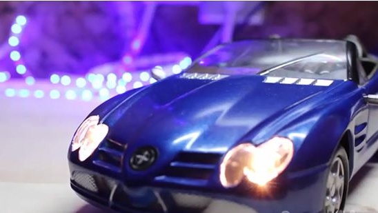
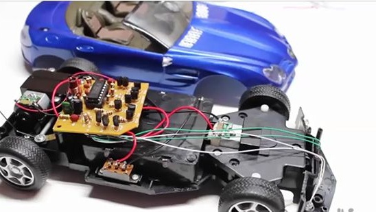
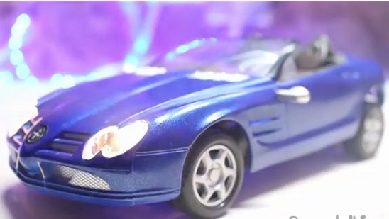
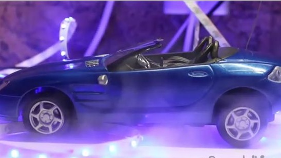
After we assembled this car we got an invaluable soldering experience that is always useful to us in everyday life. And also we got a wonderful car on the radio control, which is not a shame to give the child well or play on our own. And if you assembled this kit with your child, then he will definitely get unforgettable impressions of the assembly and a great time with you, and even as a result, you will get a car that can move around.
This set is characterized by low, but not stable cost in Chinese stores. This set is profitable to buy up to four hundred rubles.
Also, you have a wonderful opportunity to watch a video assembly of this homemade product.
[media = https: //www.youtube.com/watch? v = 0w-A8VbTY_A & t = 5s]