
Hello to all lovers homemade. Probably every beginner amateur radio fan dreamed of assembling his first sound amplifier with good quality, which could later be used for some of his purposes or to create a homemade product. In this article I will tell you how to make a sound amplifier on a TDA 2030 chip with good sound performance do it yourself using the kit kit, which can be ordered by the link at the end of the article.
Before reading this article, I suggest watching a video that details the assembly of this amplifier and checking the sound on different speakers.
In order to make a sound amplifier on a TDA 2030 chip with your own hands, you will need:
* Kit
* Soldering iron, solder, flux
* Side cutters
* A speaker with a power of at least 10 W and a resistance of 4 ohms
* Home-made clip for fixing boards
* Power supply for 12-15V
* Multimeter
* Crosshead screwdriver
Step one.
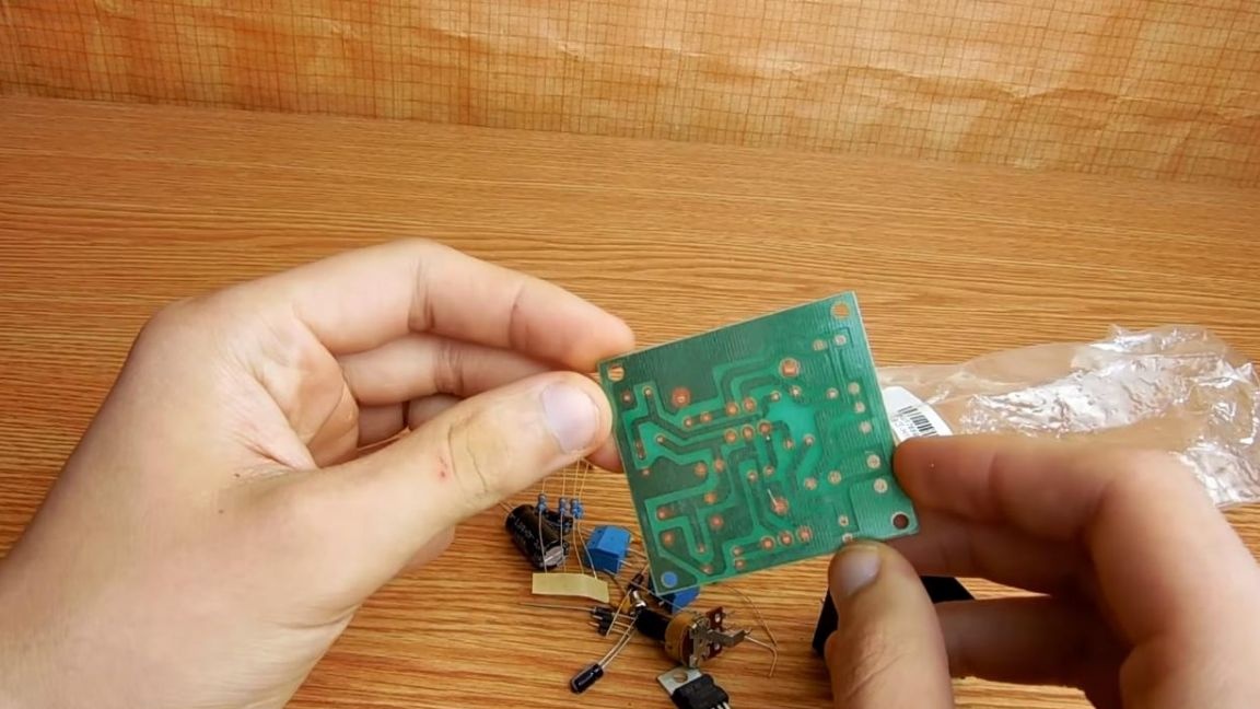
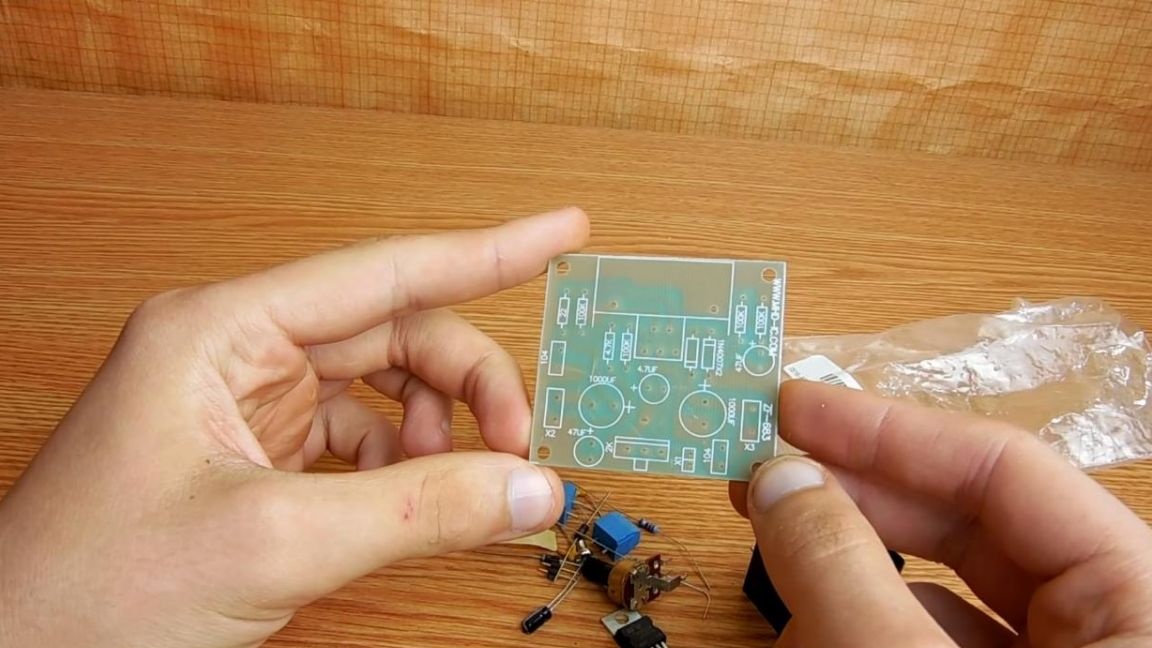
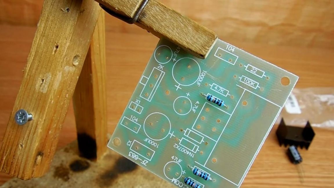
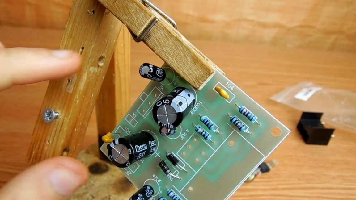
First of all, you need to inspect the board, its quality can be considered quite good, in this case it is one-sided and all details are marked on its upper part, which is very good.
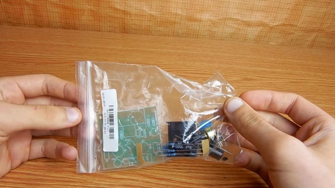
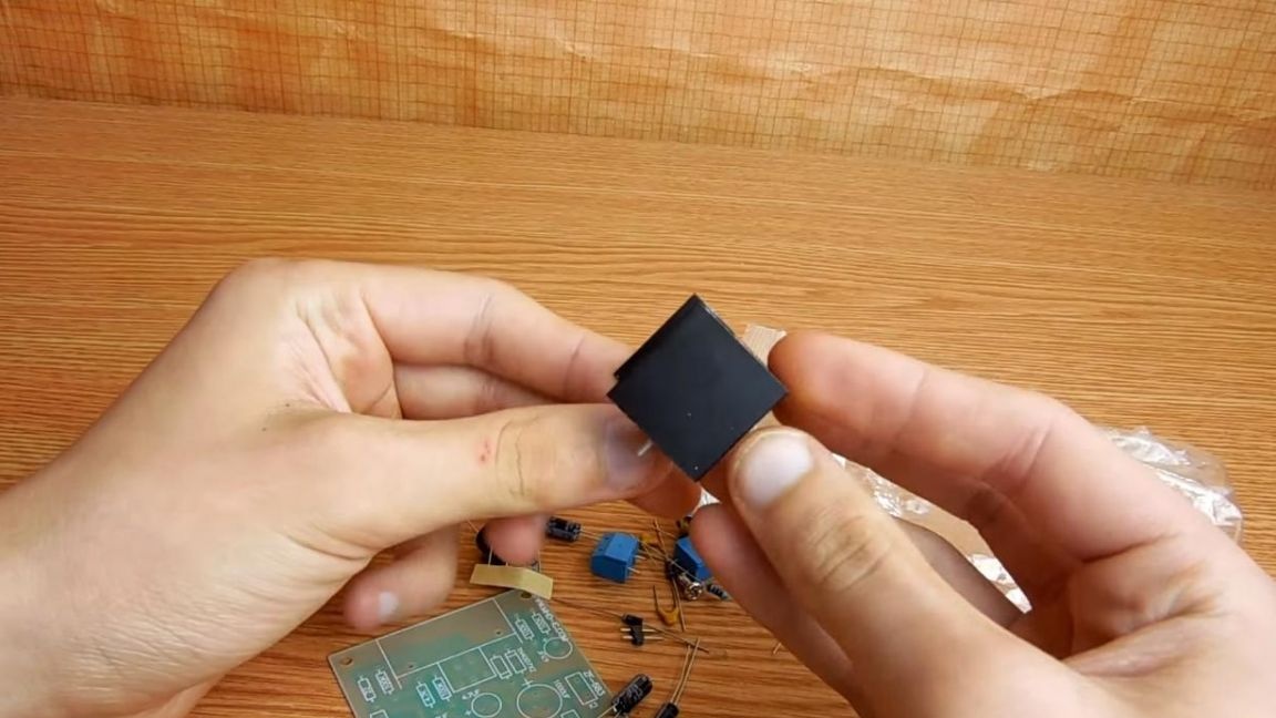
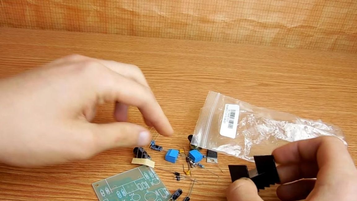
In the kit we are met by many components, as well as a TDA 2030 chip with an aluminum radiator and a variable resistor with a handle will be here as a volume control.
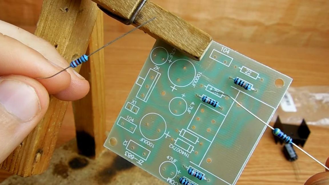
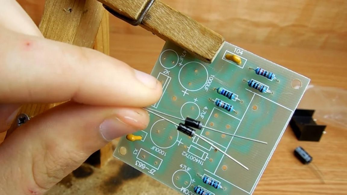
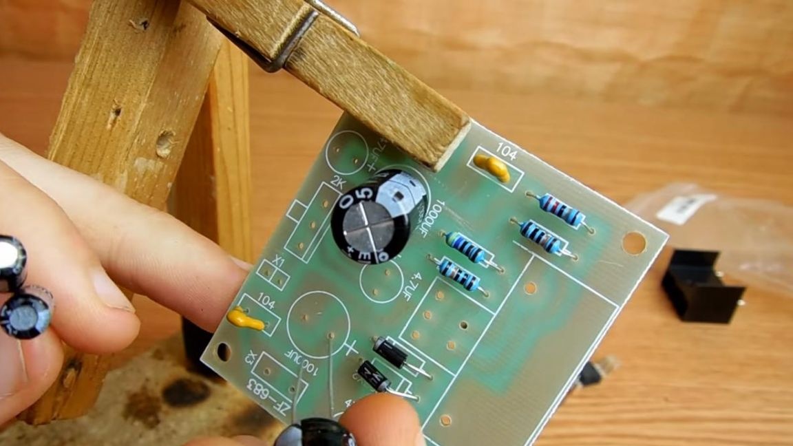
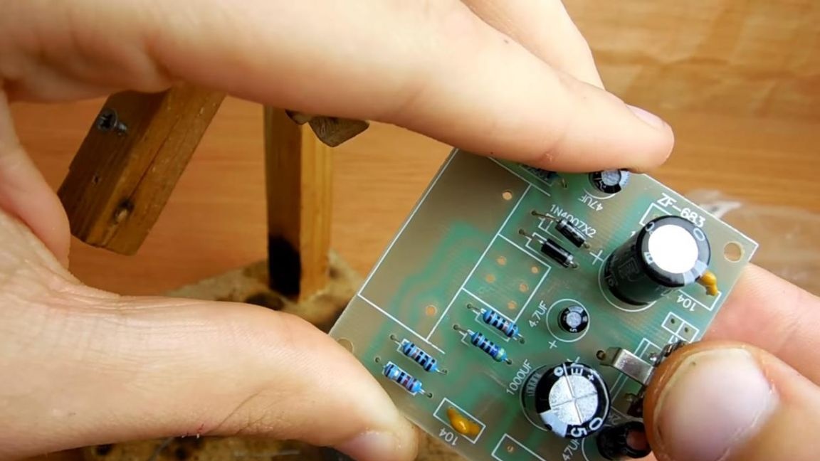
Let's start the assembly process. The first components that need to be installed on the board are resistors, there are 6 of them in the circuit and 4 of them have the same rating, namely 100 kOhm, so first we install 4 resistors with the same color strips.
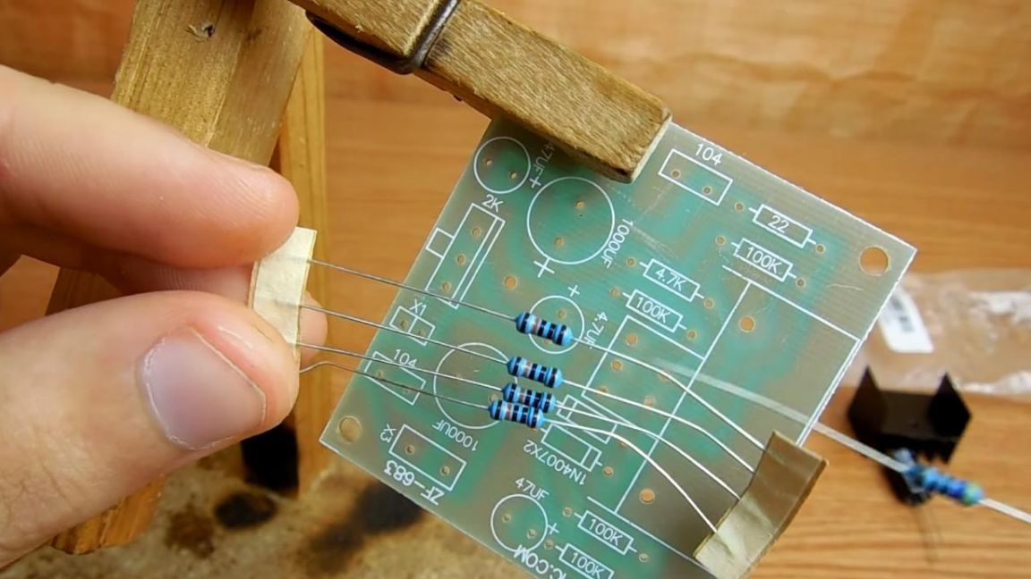
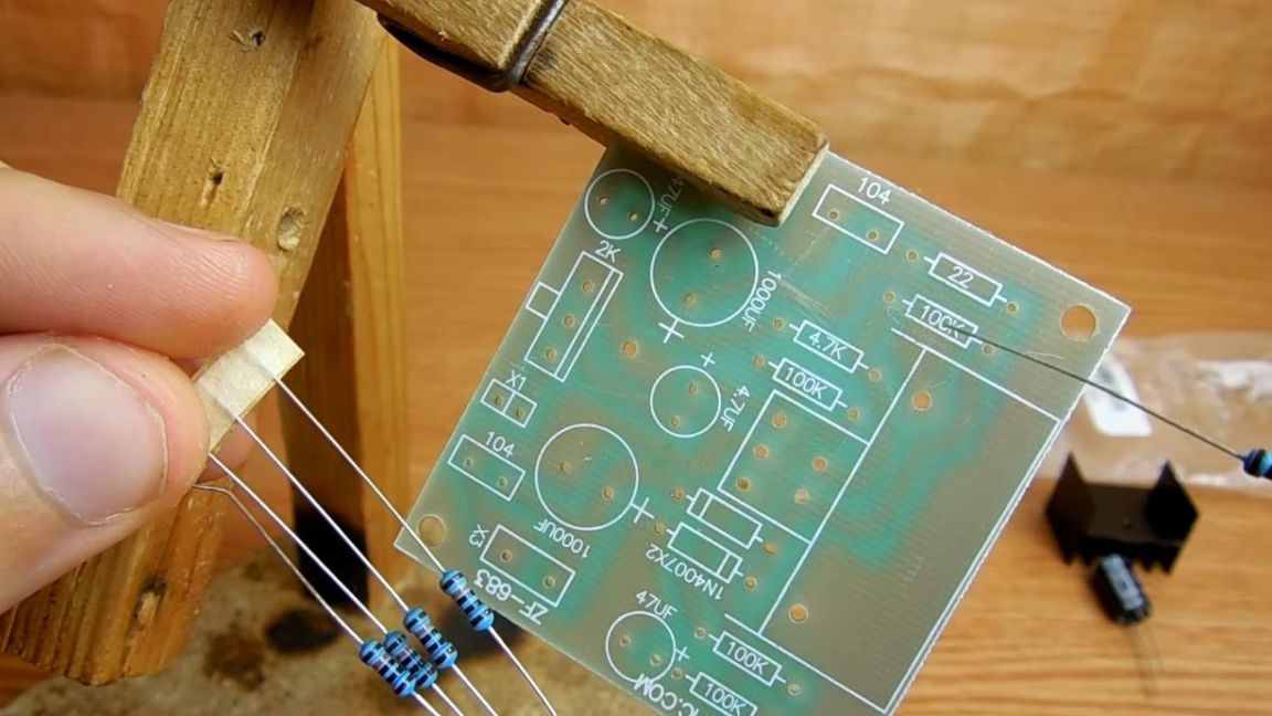
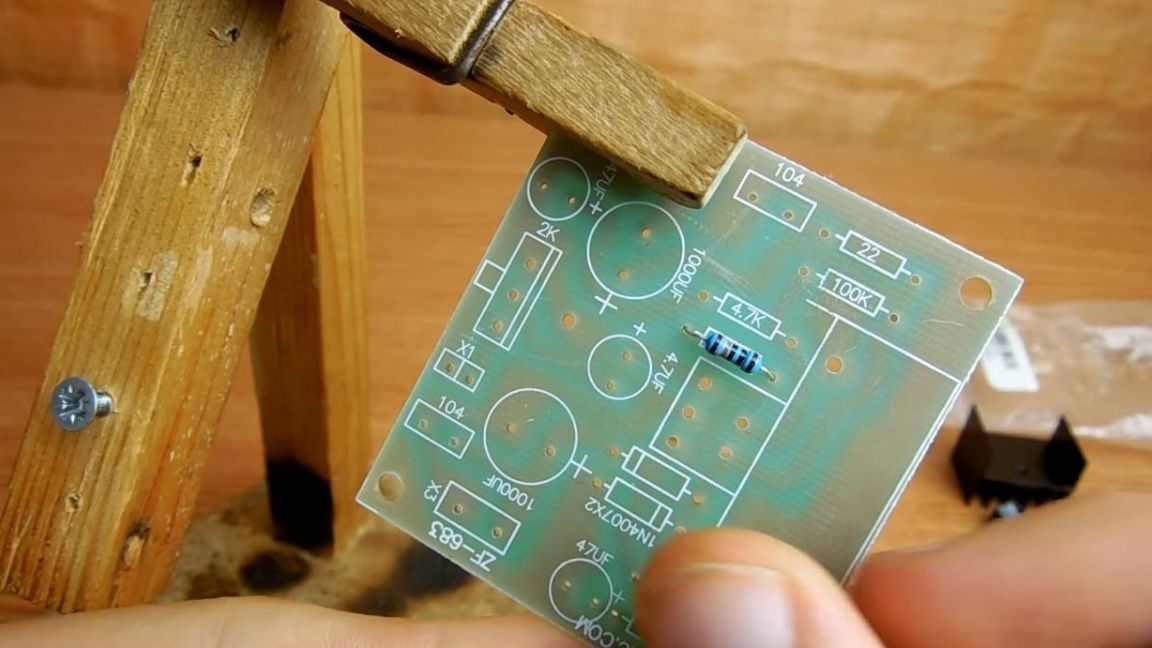
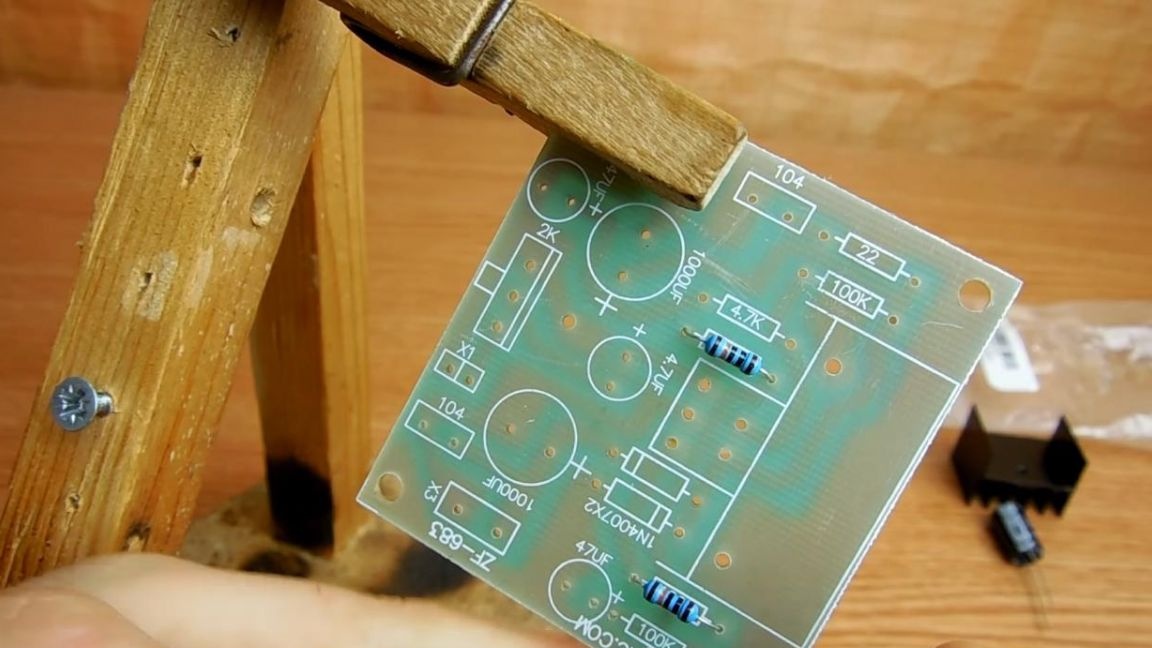

Next, the next two resistors, the resistance of which can be found using a multimeter or use the look-up table, where you can use the color coding to determine the nominal resistance of an individual resistor. Having determined the resistance of the resistors, we install them in their places on the board.
Step Two
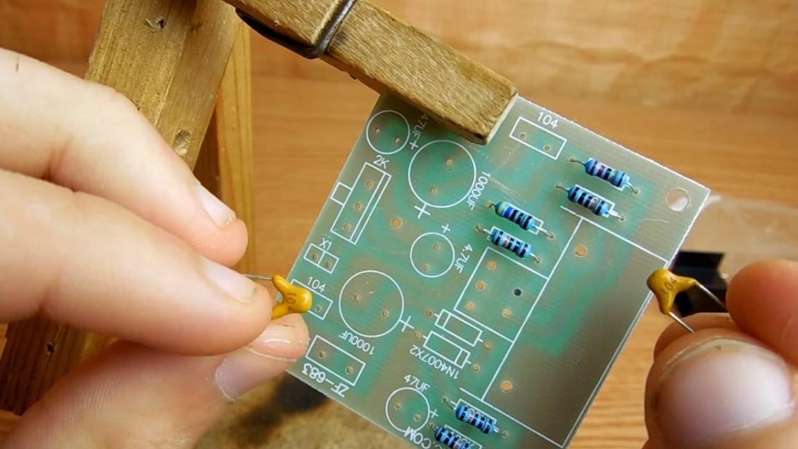
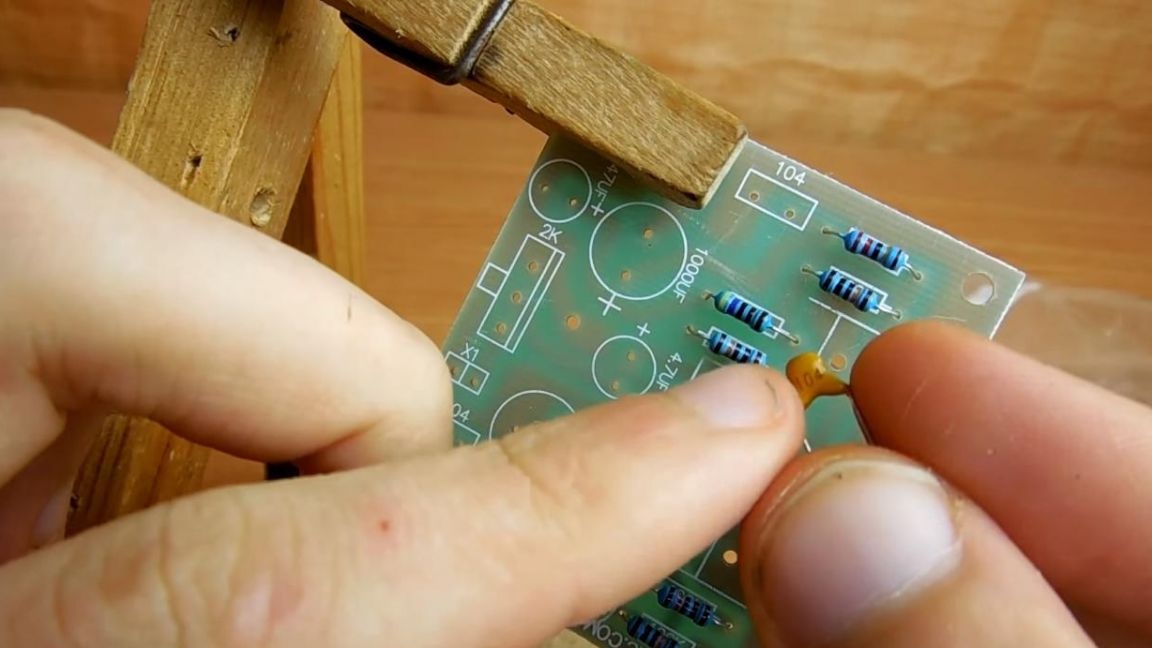
Now we install non-polar ceramic capacitors on the board, on their case there is a marking with the number 104, for them there are two places on the board, we install and bend the legs on the back so that they do not fall out when soldering.
Step Three
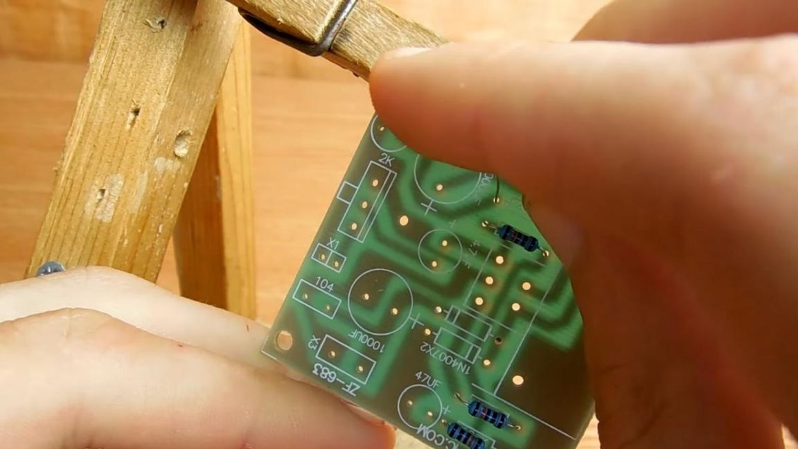
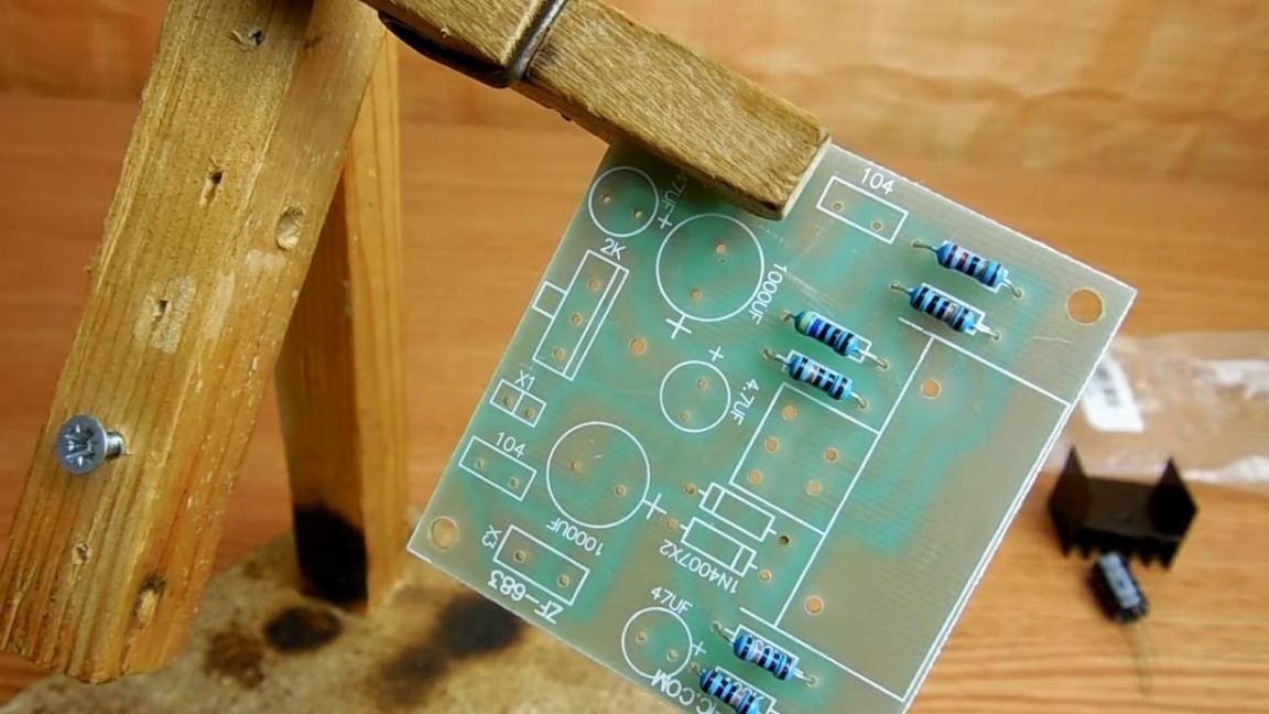
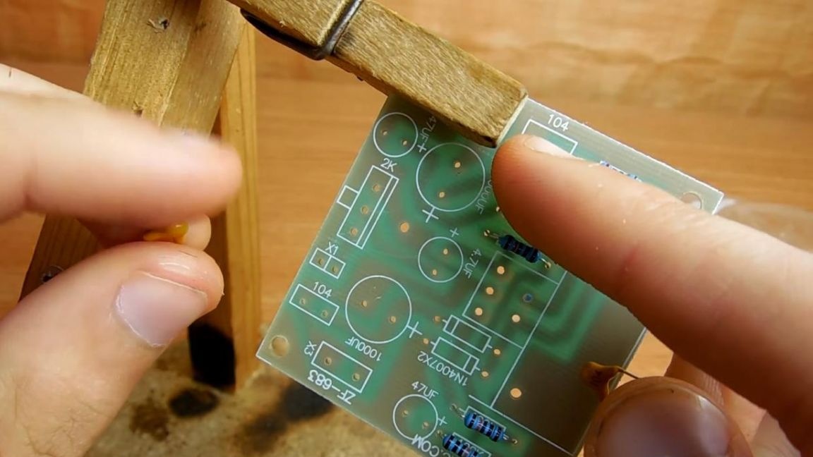
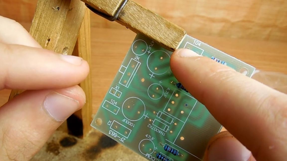
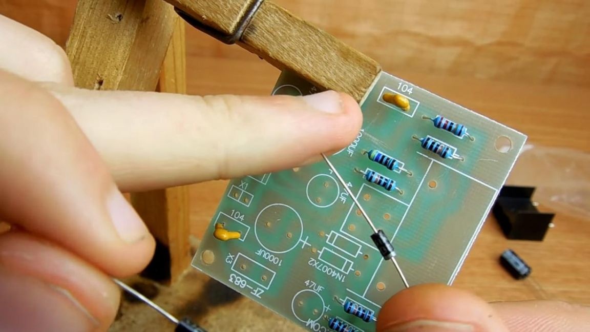
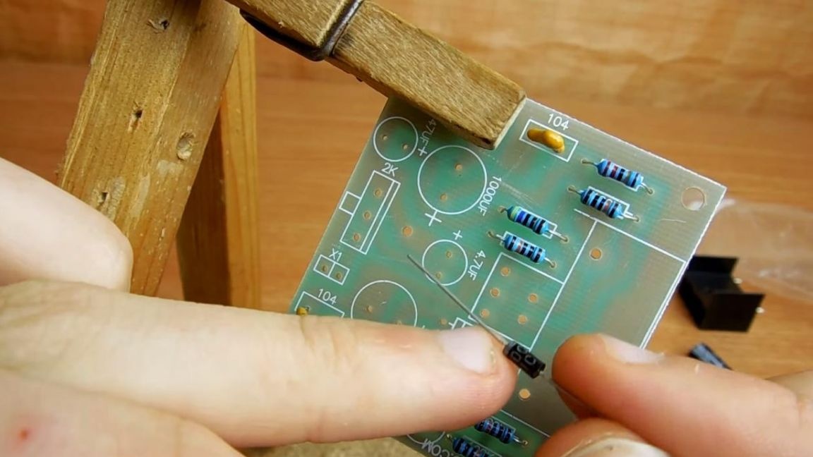
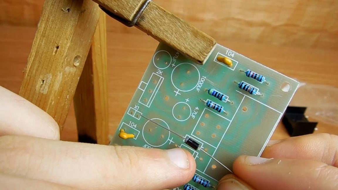
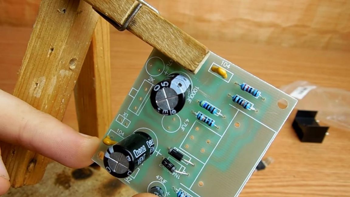
Next, there are diodes behind the capacitors, there are two in the set, we install them according to the strip on the case and the board, placing them in the same direction.
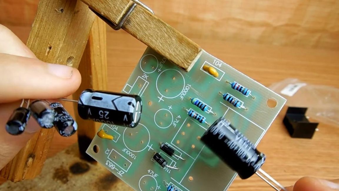
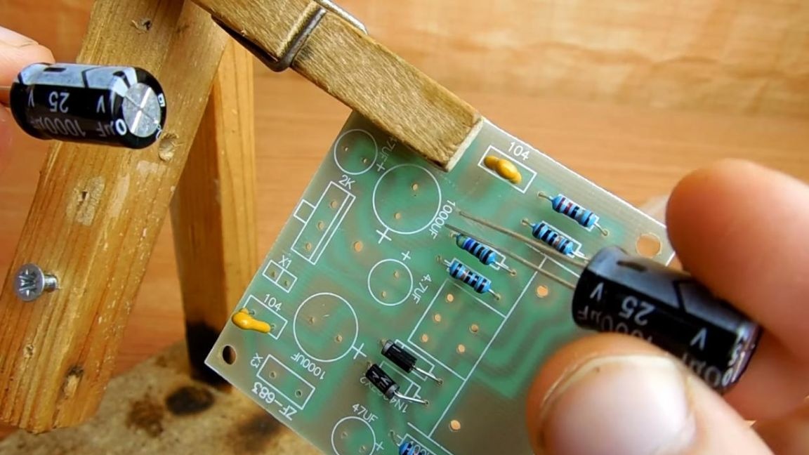
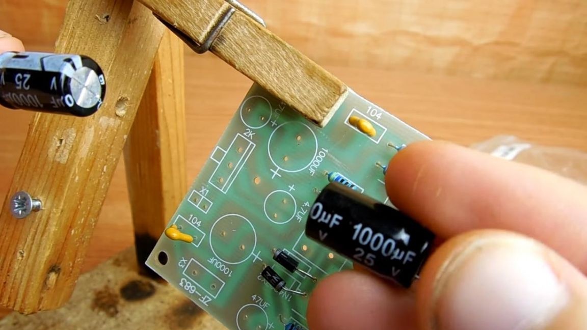
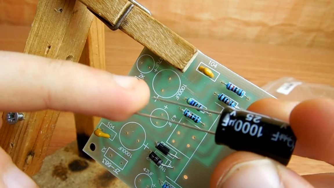
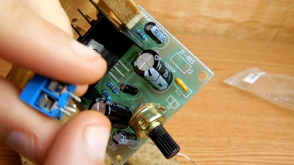
After installing the diodes, we take on the capacitors. In this case
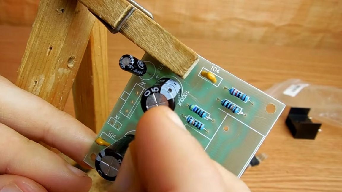
complete with as many as five polar capacitors. The ratings of each are signed on the case itself, as well as printed on the board.For proper installation, we place a long leg of the capacitor with a plus on the board or with the help of a gray strip that corresponds to the minuses of the capacitor. First we install large capacitors, then small ones.
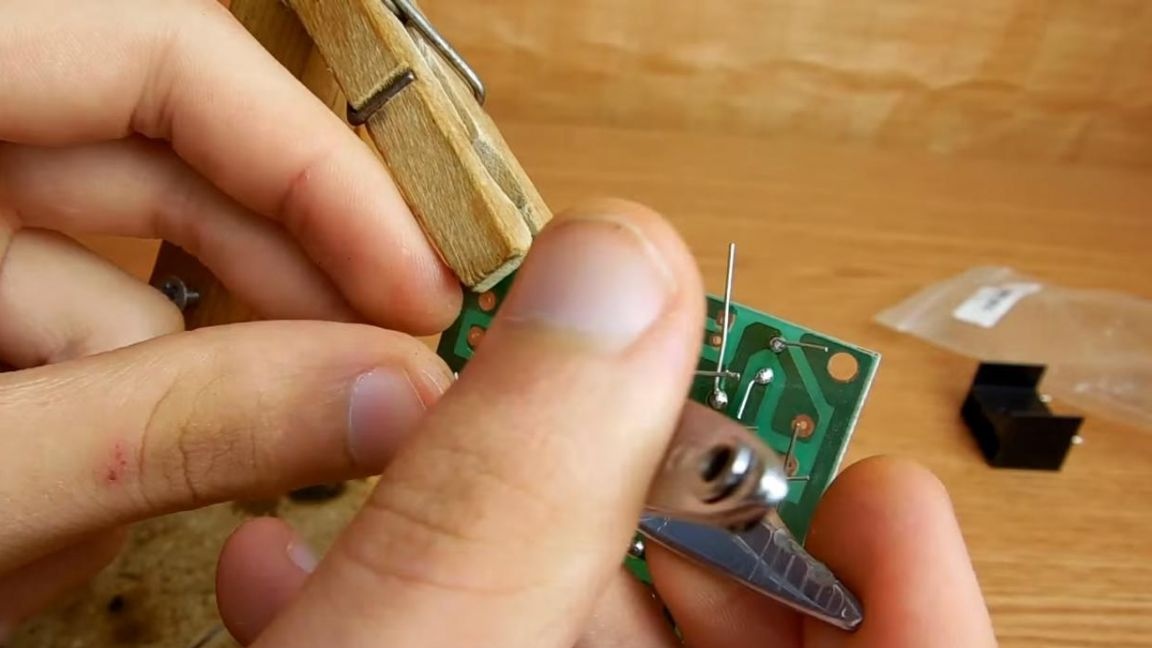
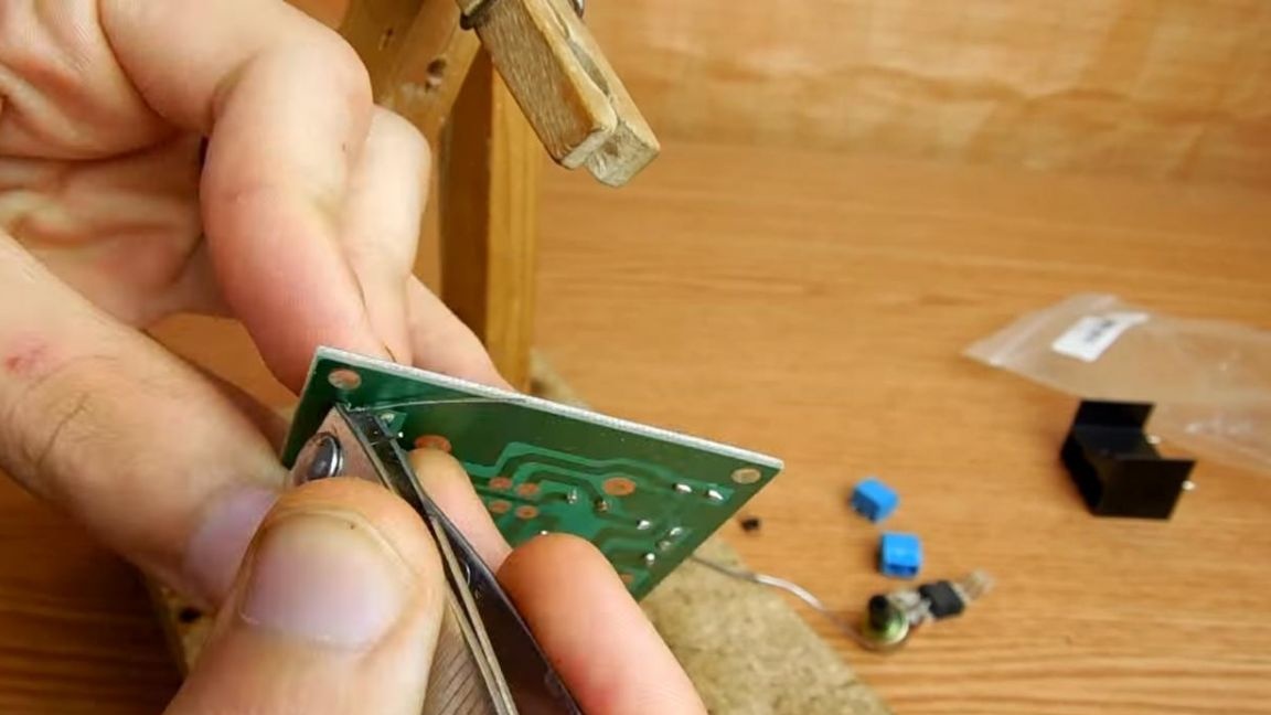
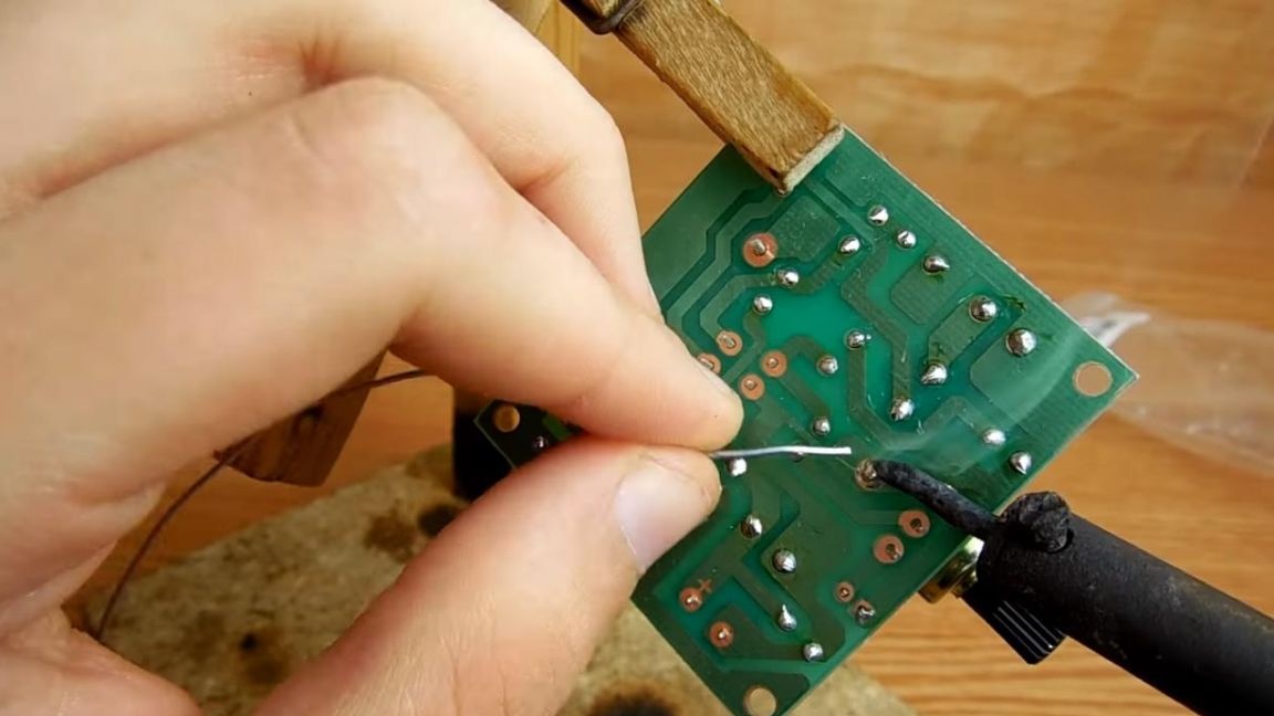
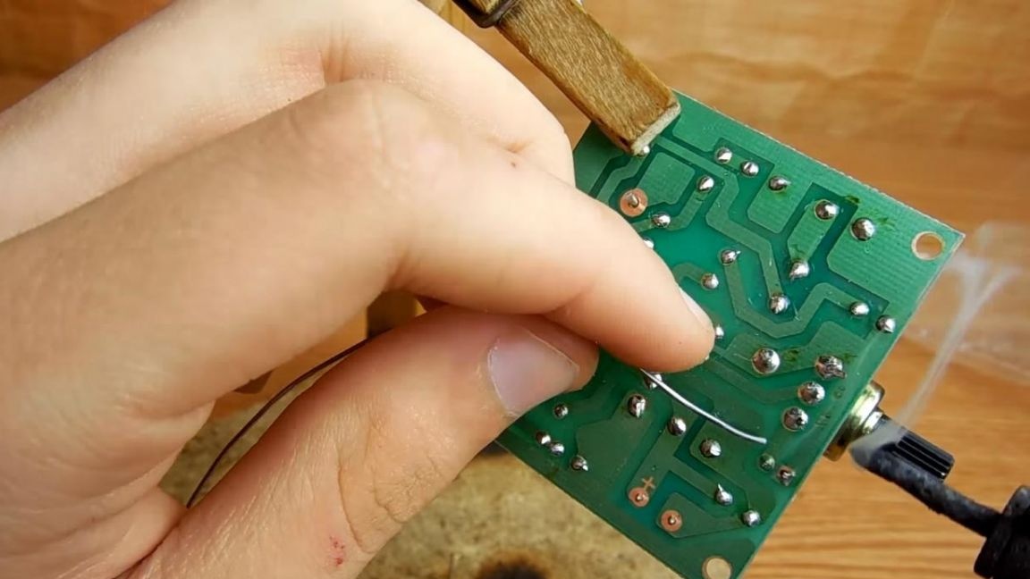
Step Four
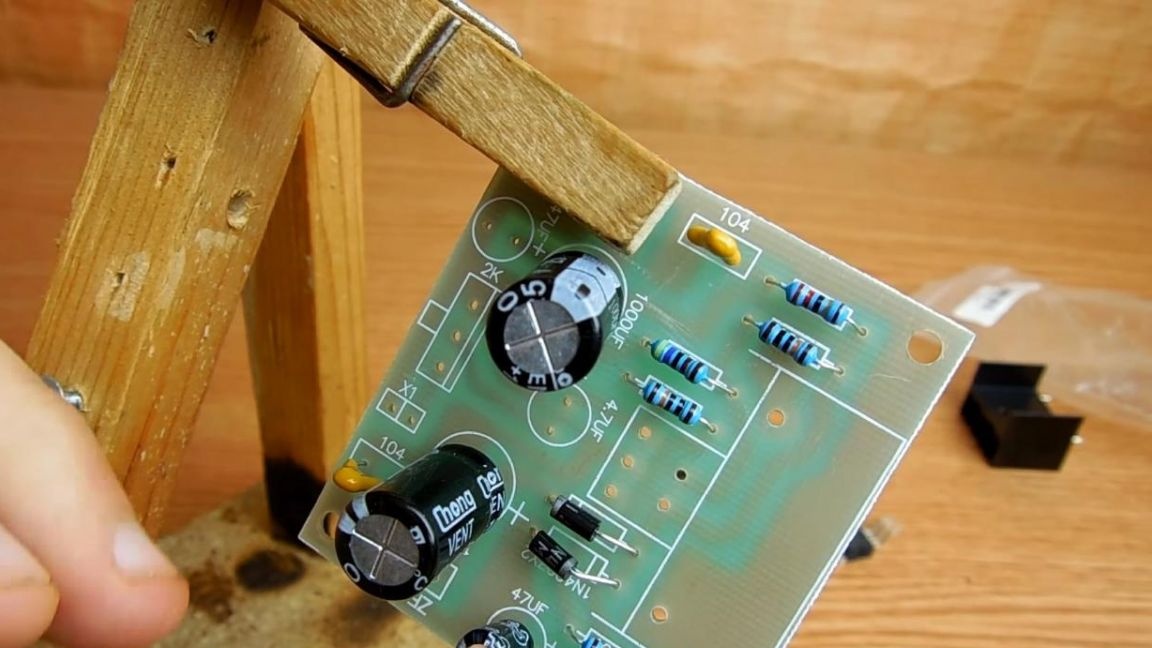
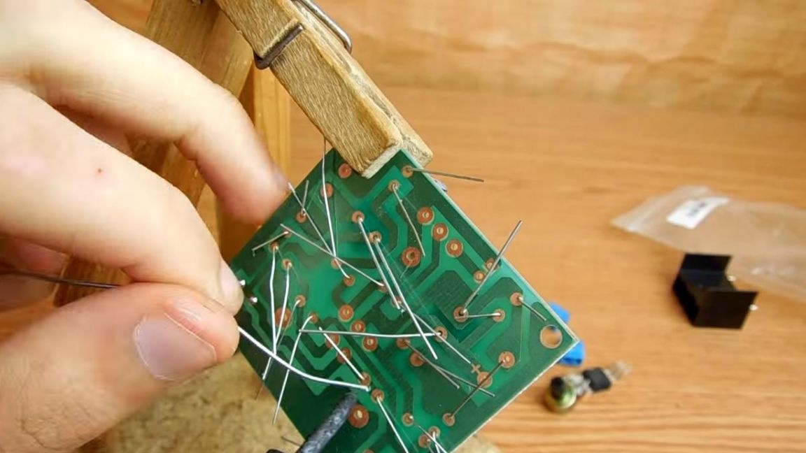
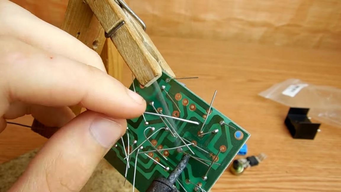
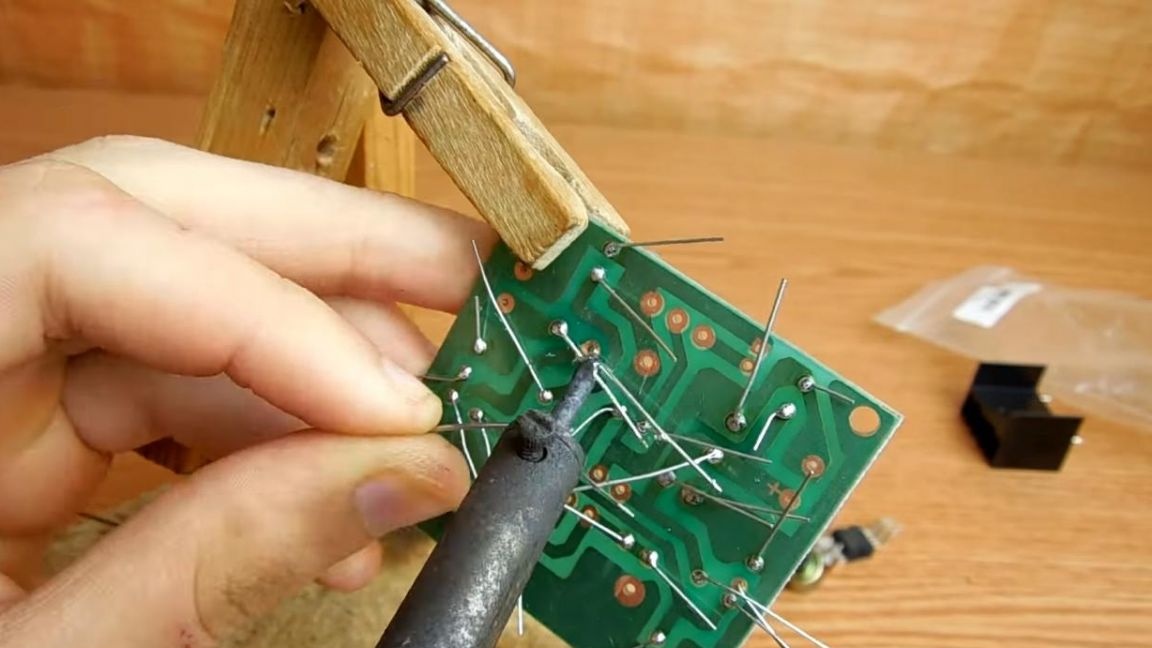
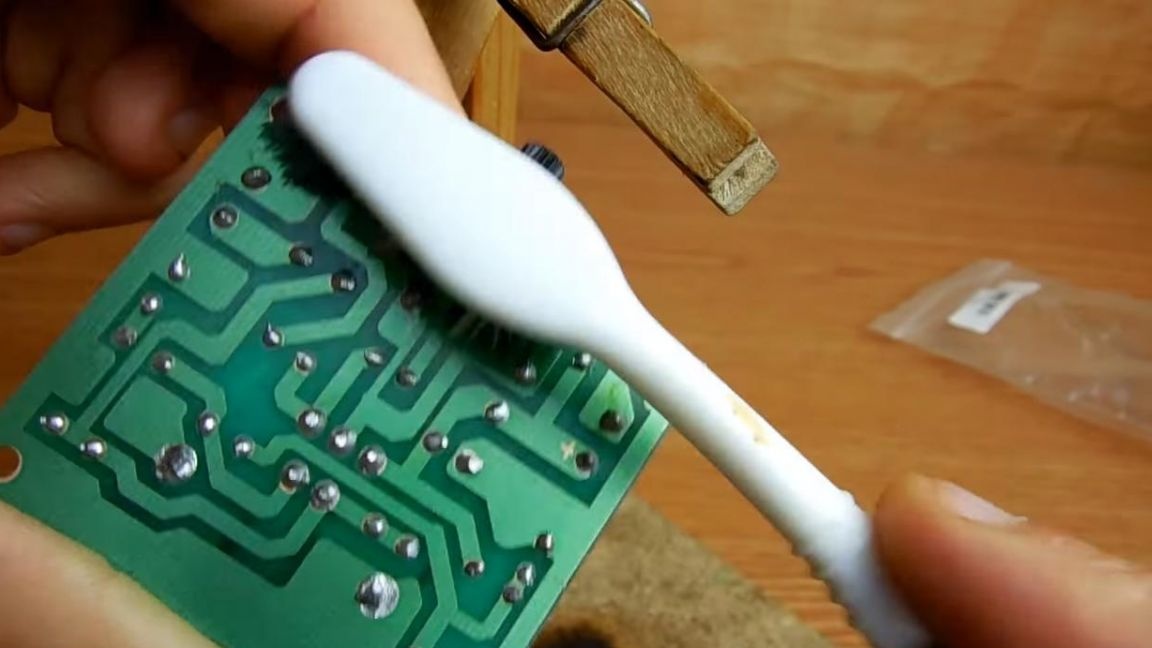
Turn the board over in the clamp and fix it for further soldering. Before proceeding to solder the findings to the board tracks, apply a flux. Next, solder the findings, gradually adding solder as needed. After soldering, remove excess leads with side cutters. When biting the legs of the components, be careful, as they can be easily bitten off along with the track, which is not a very interesting task to restore.
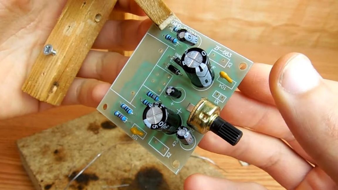
Step Five
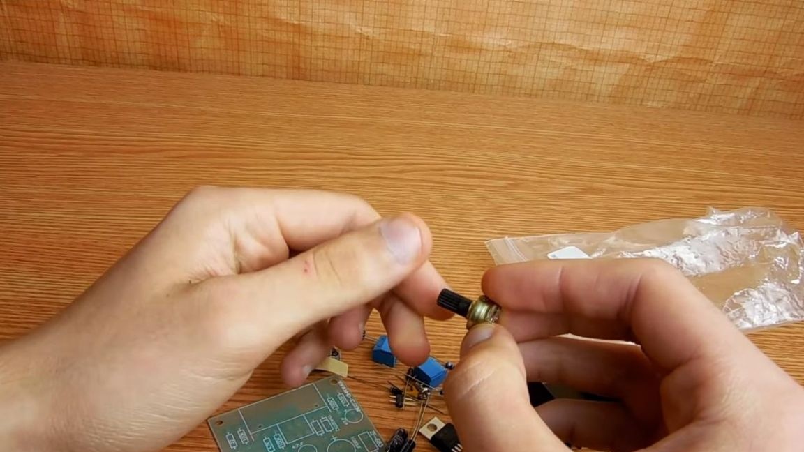
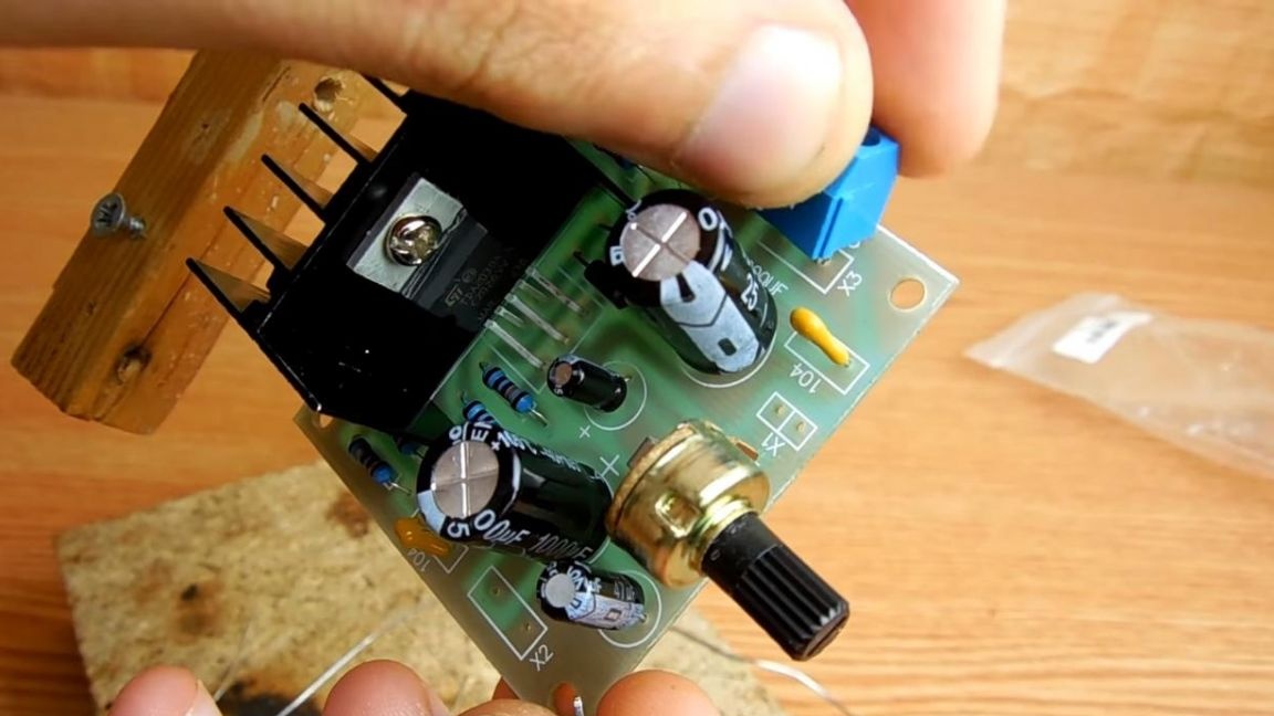
To adjust the volume level, we set a variable resistor at 100 kOhm, its fourth output serves for more solid fixation on the board.
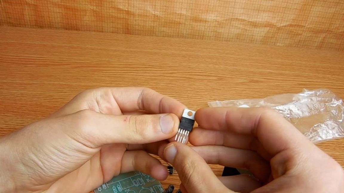
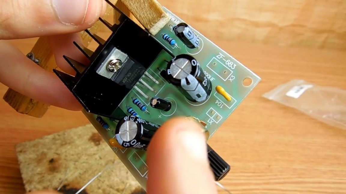
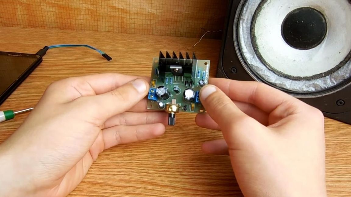
Now we fasten the microcircuit to the aluminum radiator with a screwdriver using a Phillips screwdriver, we apply thermal grease before this to remove heat. Next, already with the radiator, we place the microcircuit on the board, slightly bend the leads so that they pass into the holes for the microcircuit.
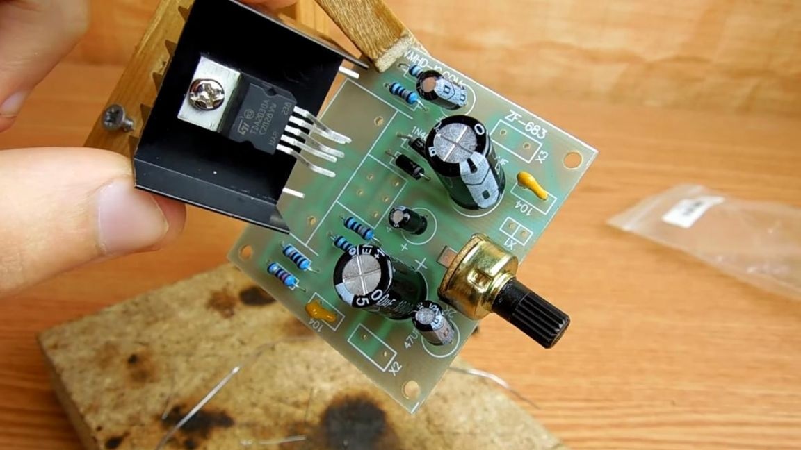
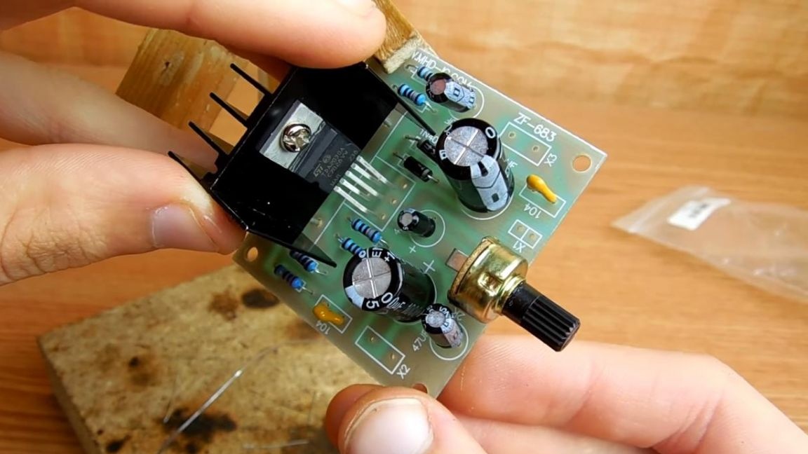
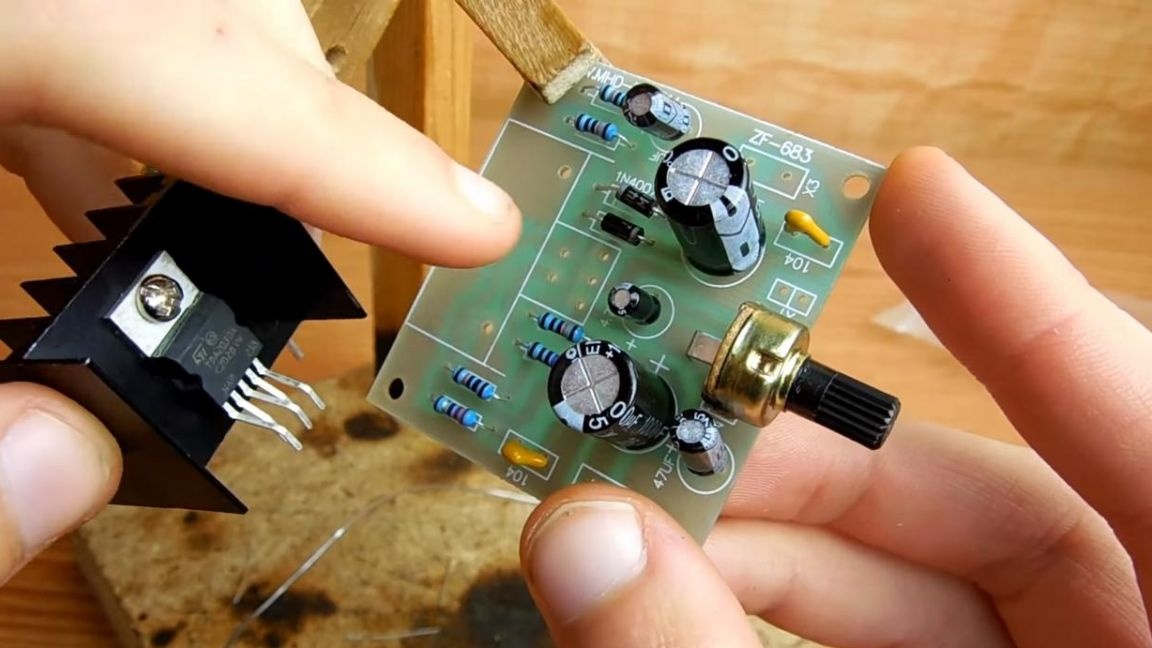
After installing the radiator with the microcircuit, we install the connectors, the power, speaker and sound input will already be connected to them.
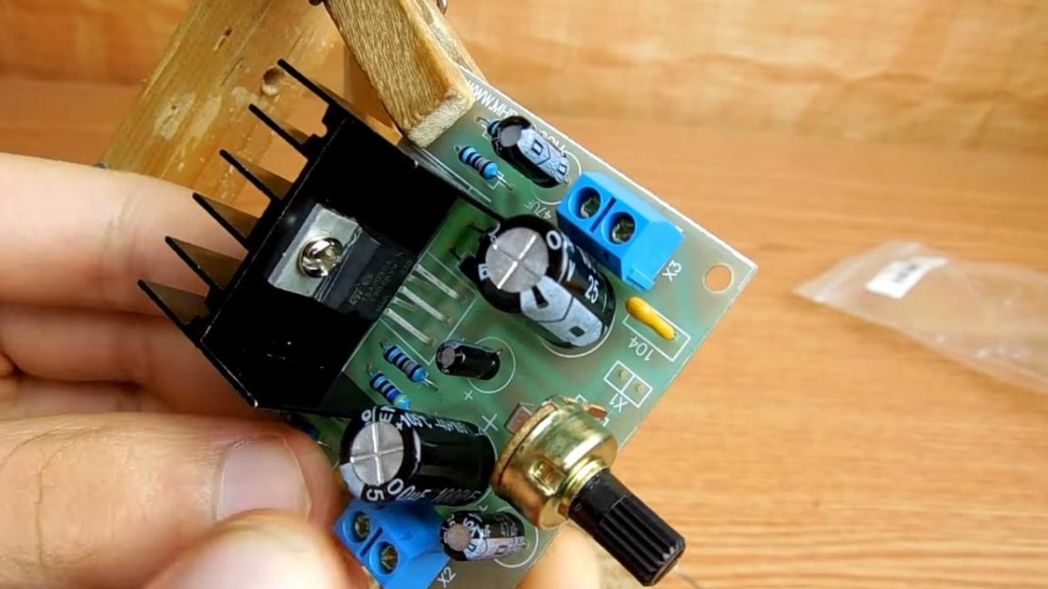
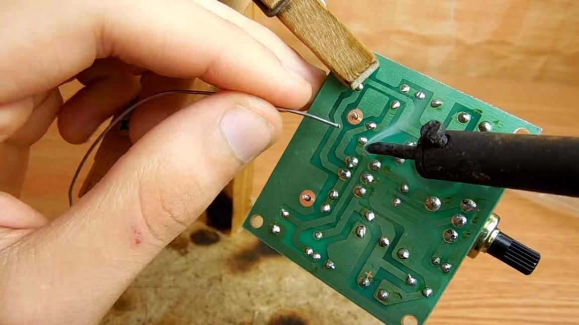
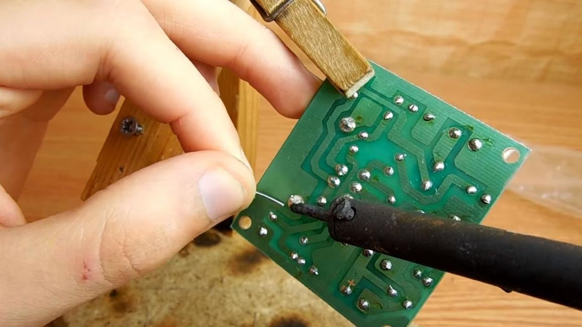
Step Six
Solder the findings of the microcircuit and connectors. After soldering, we clean the board from flux residues using galosh gasoline.
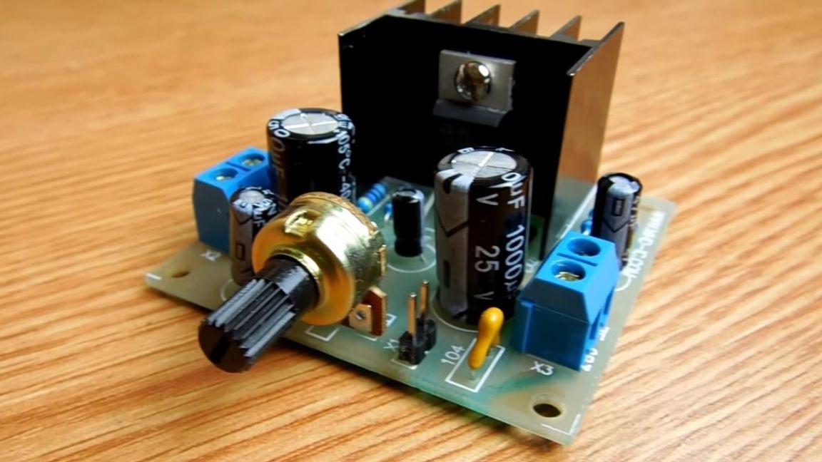
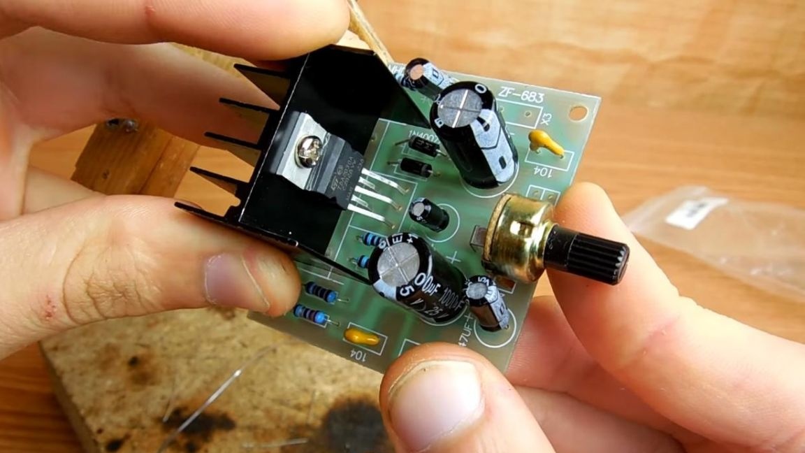
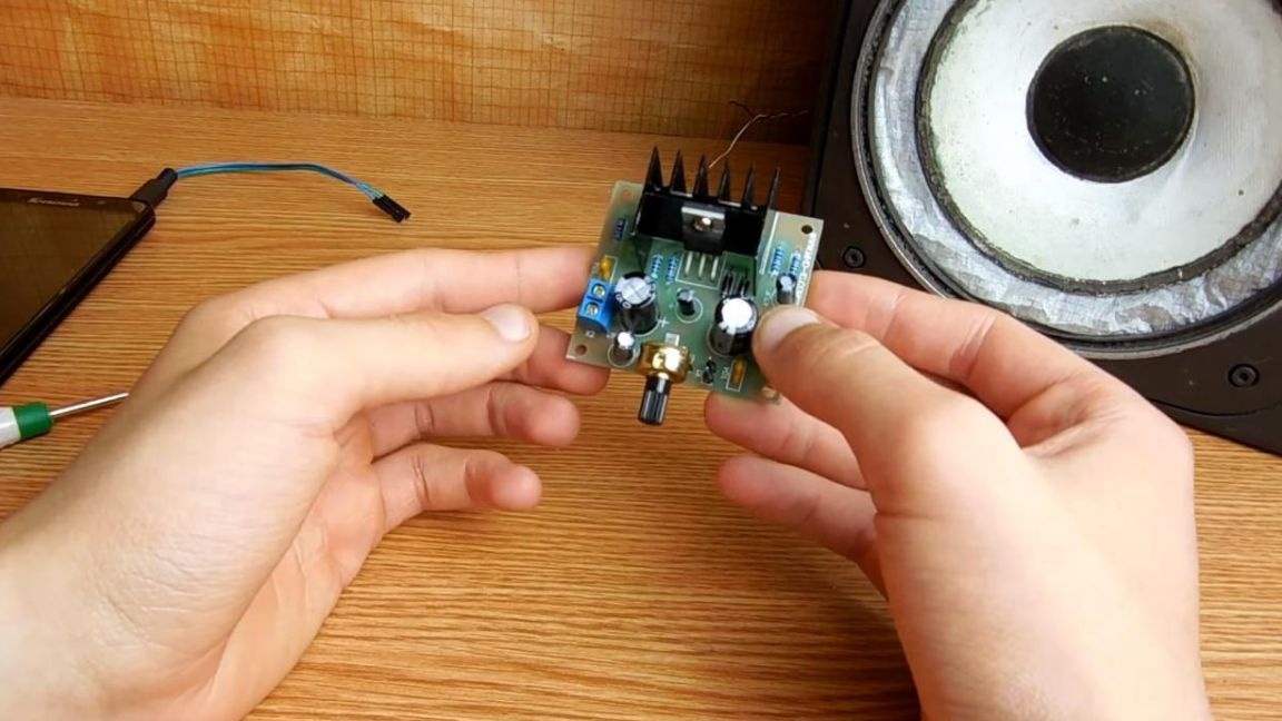
On this amplifier is ready for testing.
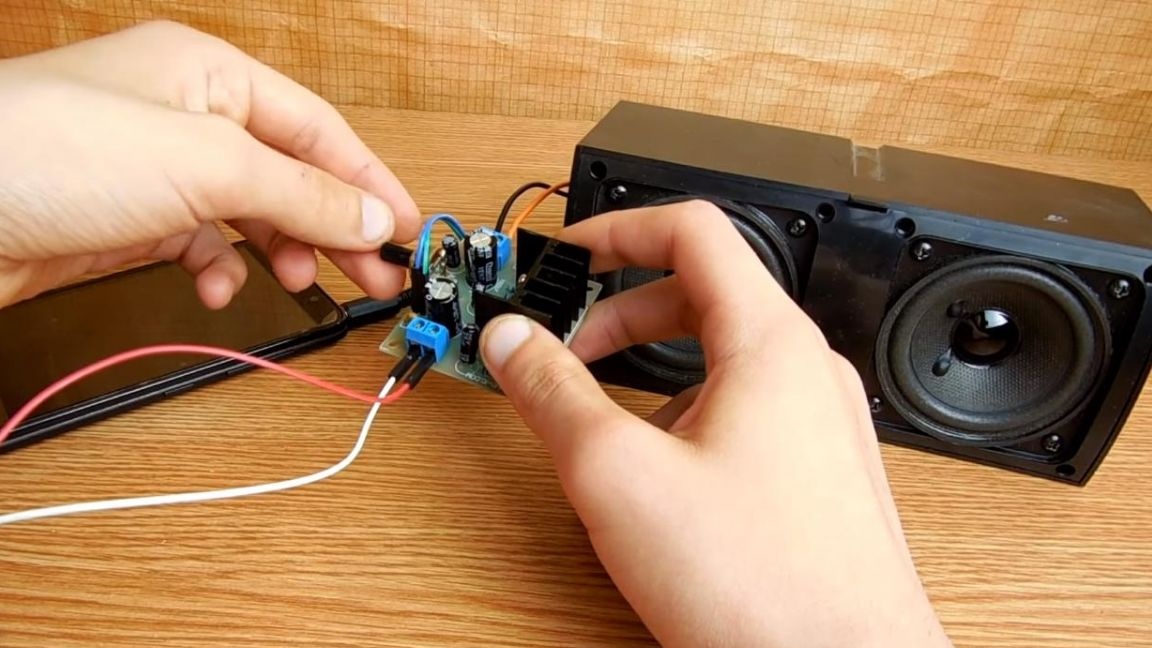
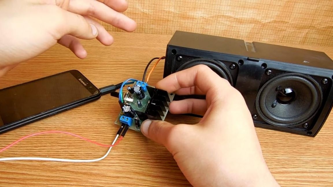
Seventh step.
We connect the speaker to the connectors, the sound input from the phone or other device and supply power from 12 to 15V. The sound from this amplifier turned out to be of a good enough level, and the amplifier itself is easily suitable for assembling columns for a computer or home acoustics.
That's all for me, thank you all for your attention and creative success.