
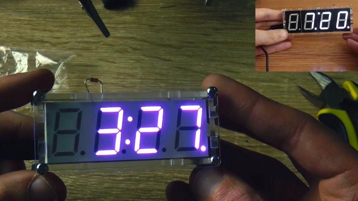
Hello to all lovers homemade. In this article I will tell you how to make a digital watch with an LED matrix using the kit kit, which can be ordered from the link at the end of the article. Such home-made watches will be an excellent indicator of the time in your home, and will also show the temperature in the room, which distinguishes them from ordinary watches.
Before you read the article, I suggest watching a video that shows the assembly process of this kit kit with analysis of all the little things, and by itself checking the finished homemade product.
To make a digital LED watch do it yourself, you will need:
* Kit
* Soldering iron, solder, flux
* Side cutters
* Crosshead screwdriver
* Device for soldering "third hand"
* 5V power supply with USB output
Step one.
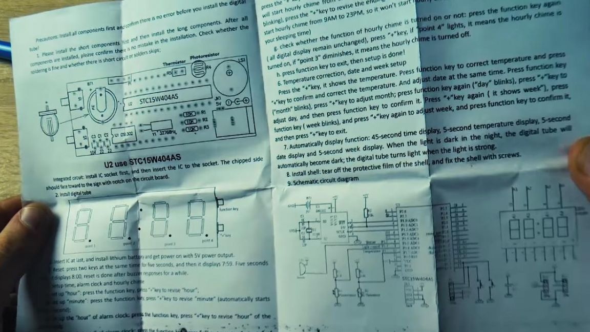
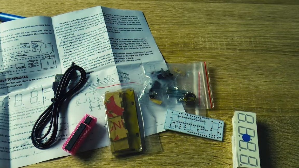
The kit kit is large enough. It contains instructions in English that will help assemble the circuit, configure it and see the face values of the radio components, since not everything is indicated on the board itself.


Also included is a USB cable, at the end of which is a plug for the power connector on the watch, from which they will be powered.
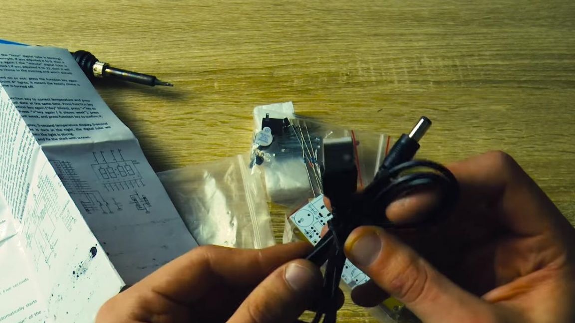
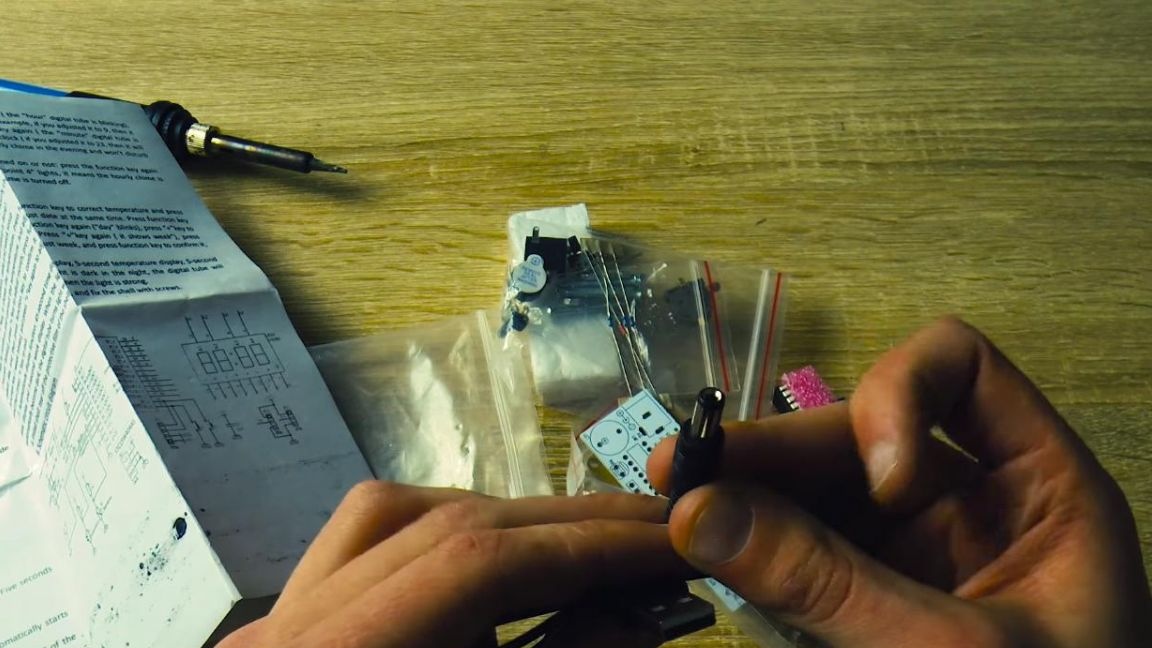
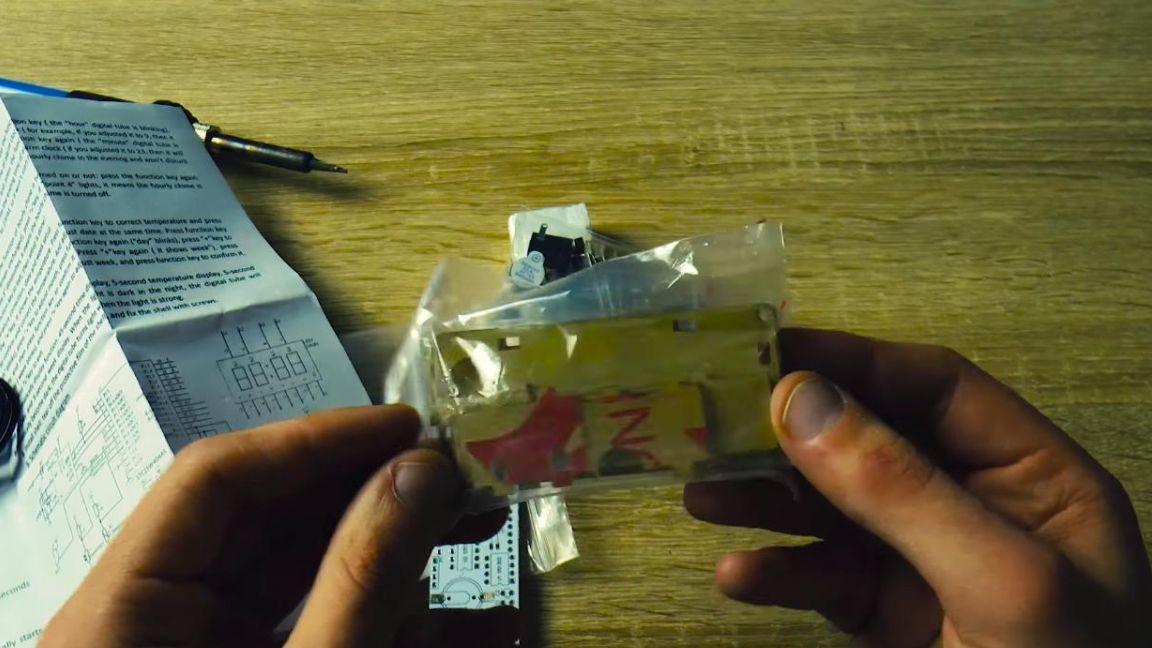
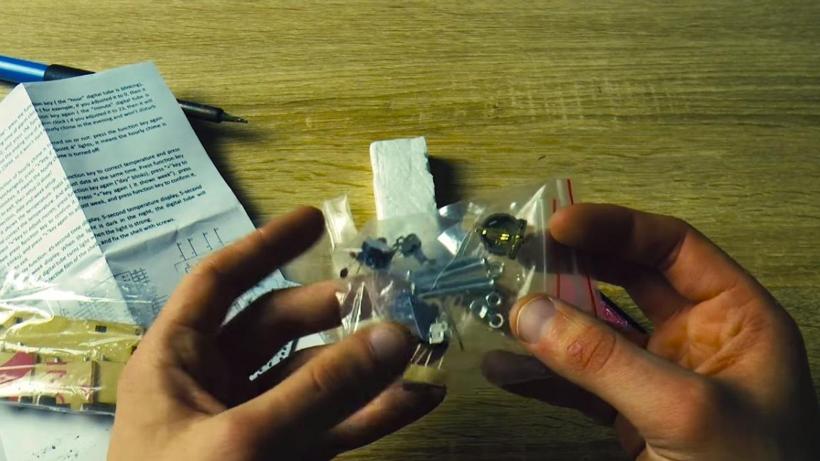
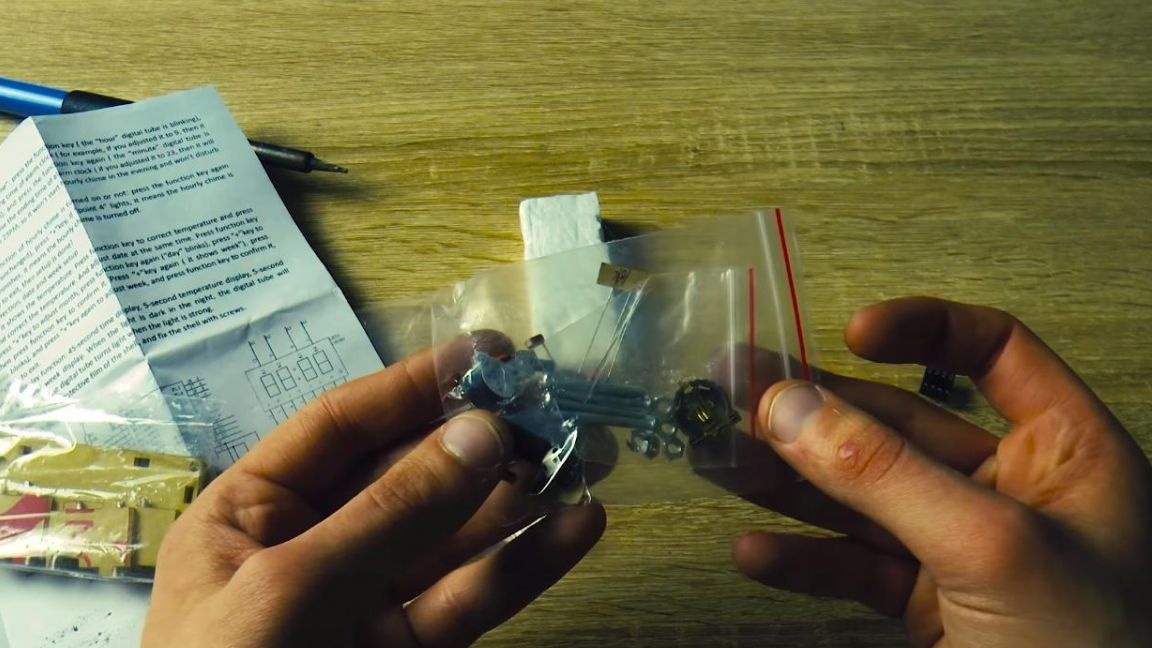
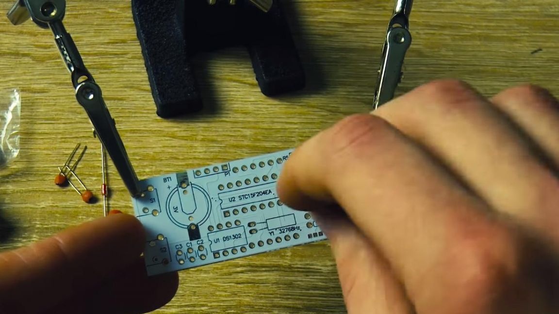
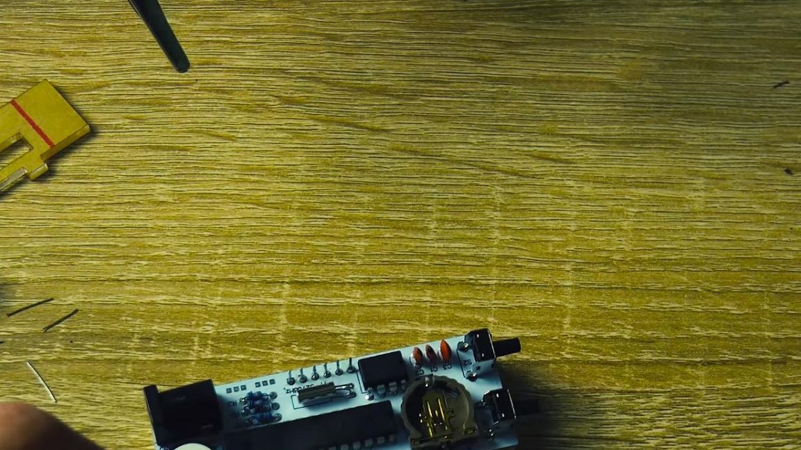
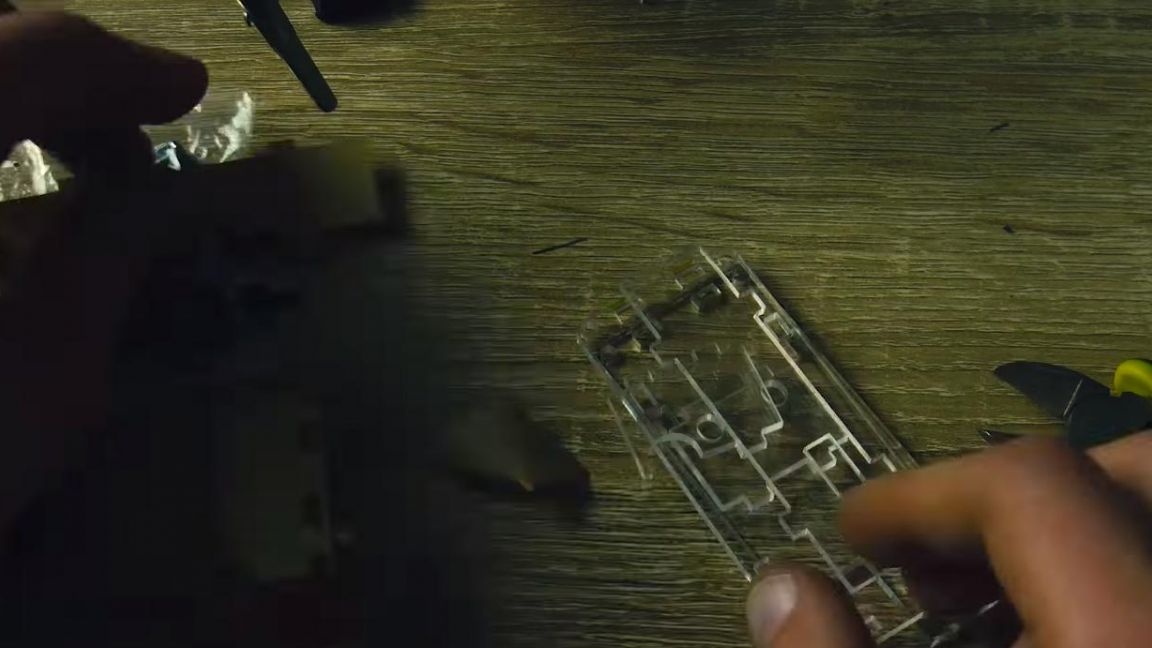
The board itself is made quite high quality. There are also plexiglass panels, which in the next will be assembled in a case and a bag with radio components and fasteners.

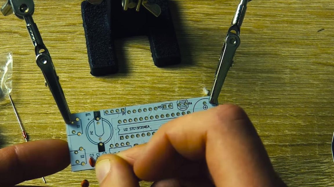
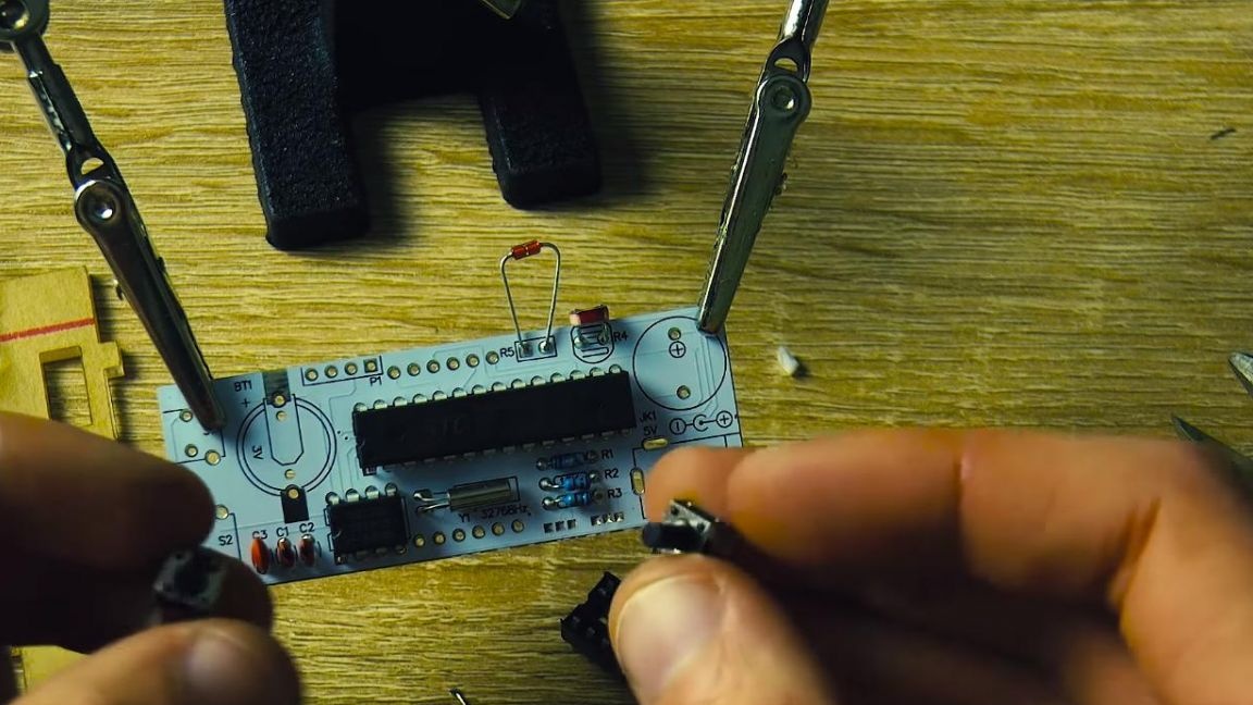
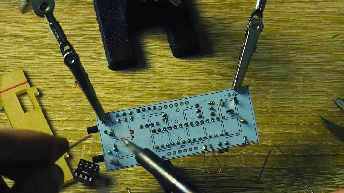
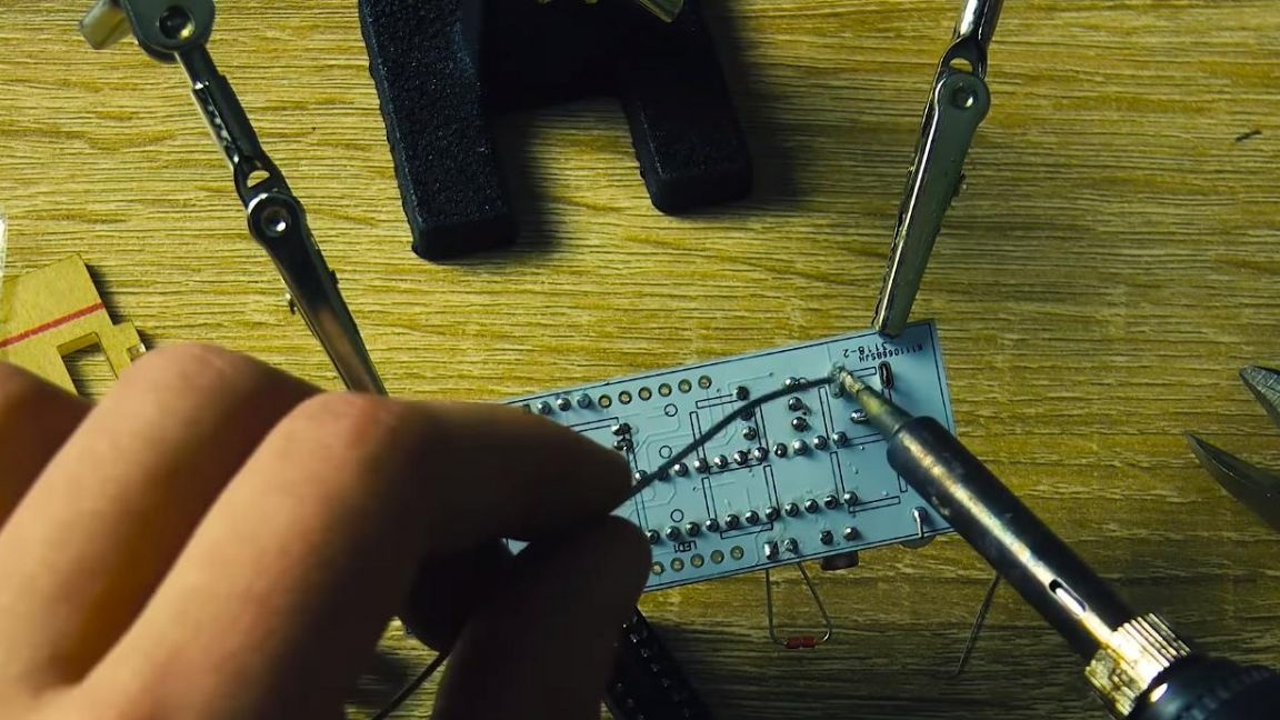
First of all, we fix the board in the third-hand soldering device and begin to arrange the resistors.
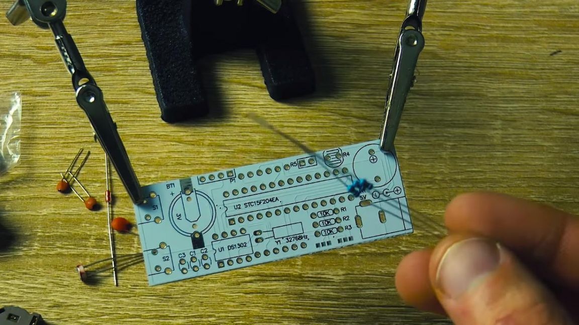
There are only three of them in the scheme, their denominations are the same and even signed on a piece of paper on which they were fixed in the kit.
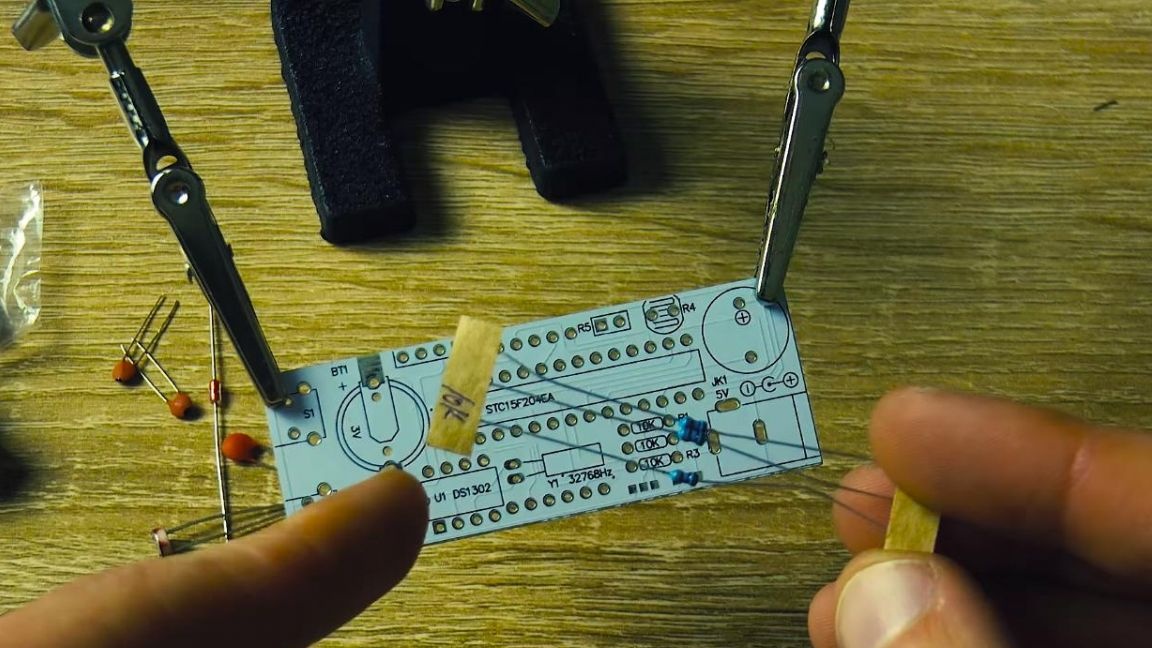
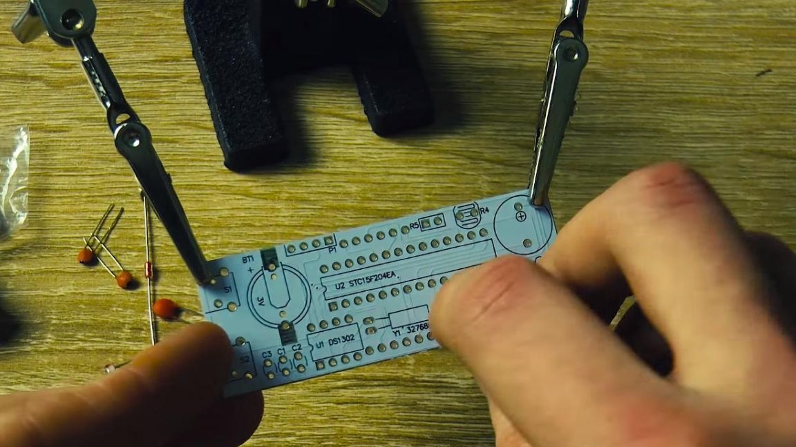
Conveniently, it is not necessary to determine the resistance of the resistors here, so we simply install these resistors on the board with the words R1, R2 and R3. In order to prevent the radio components from falling out when soldering, we follow up with the conclusions.
Step Two
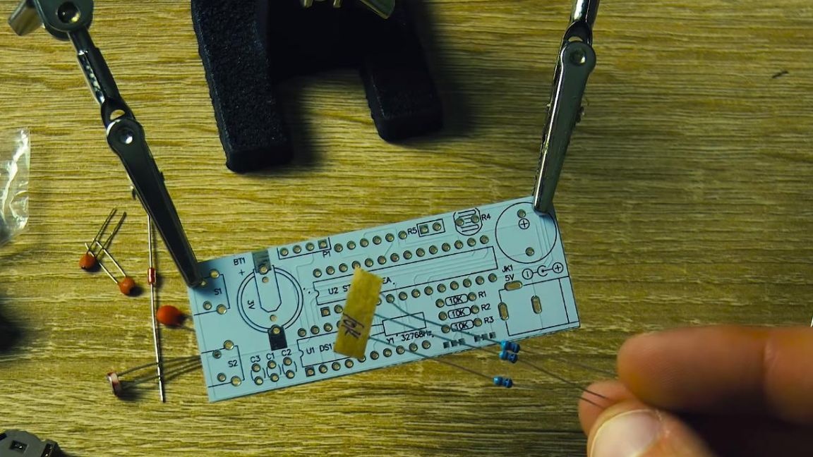
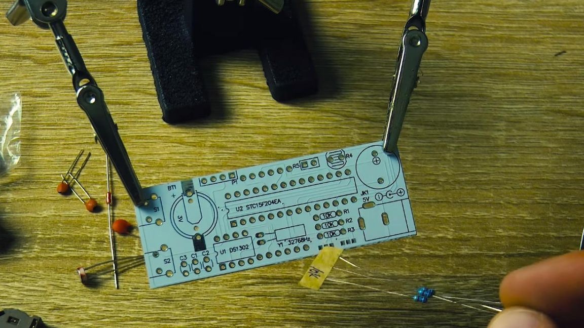
Next, we put ceramic non-polar capacitors on the board, their ratings in this case are different and are signed on the case.
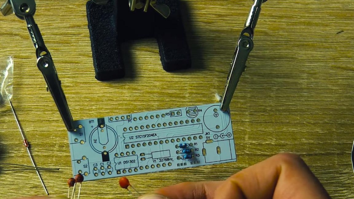

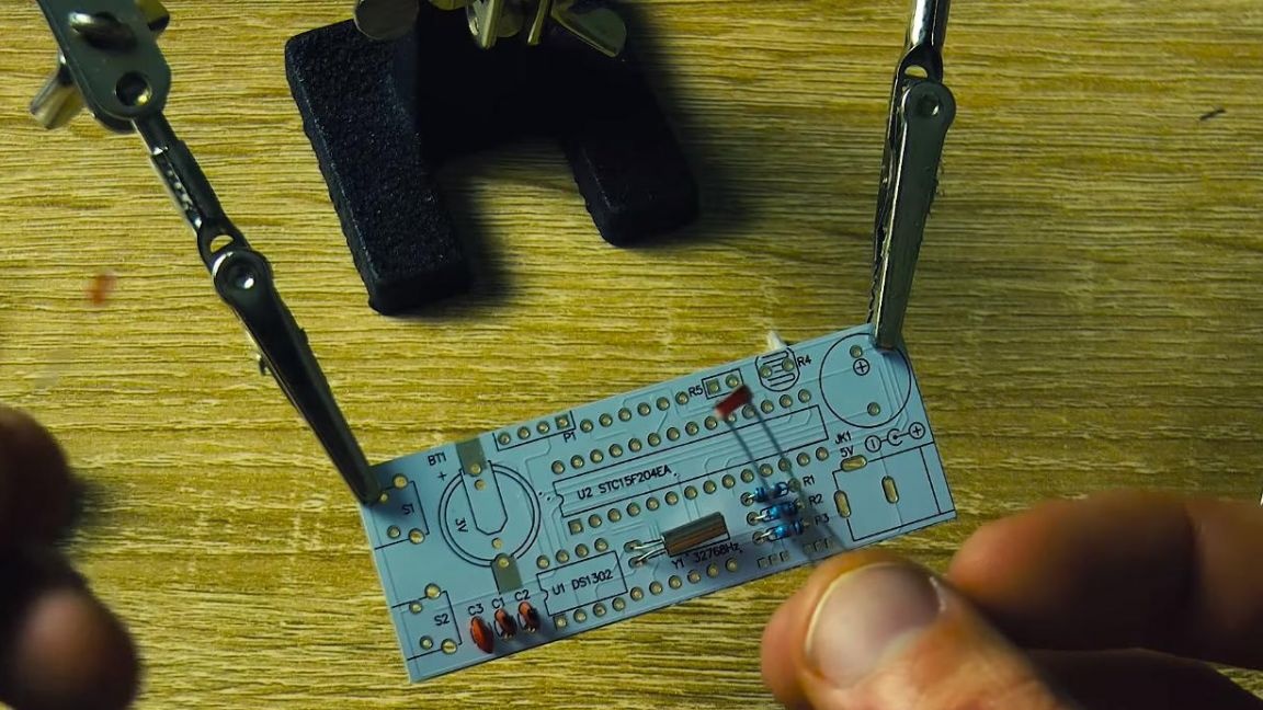
In the circuit we have three of them, two of them with a capacity of 22pF with the number 22 on the case and one capacitor at 0.1 pF with the number 104 on the case. In which order we put them, we follow the instructions.
Step Three
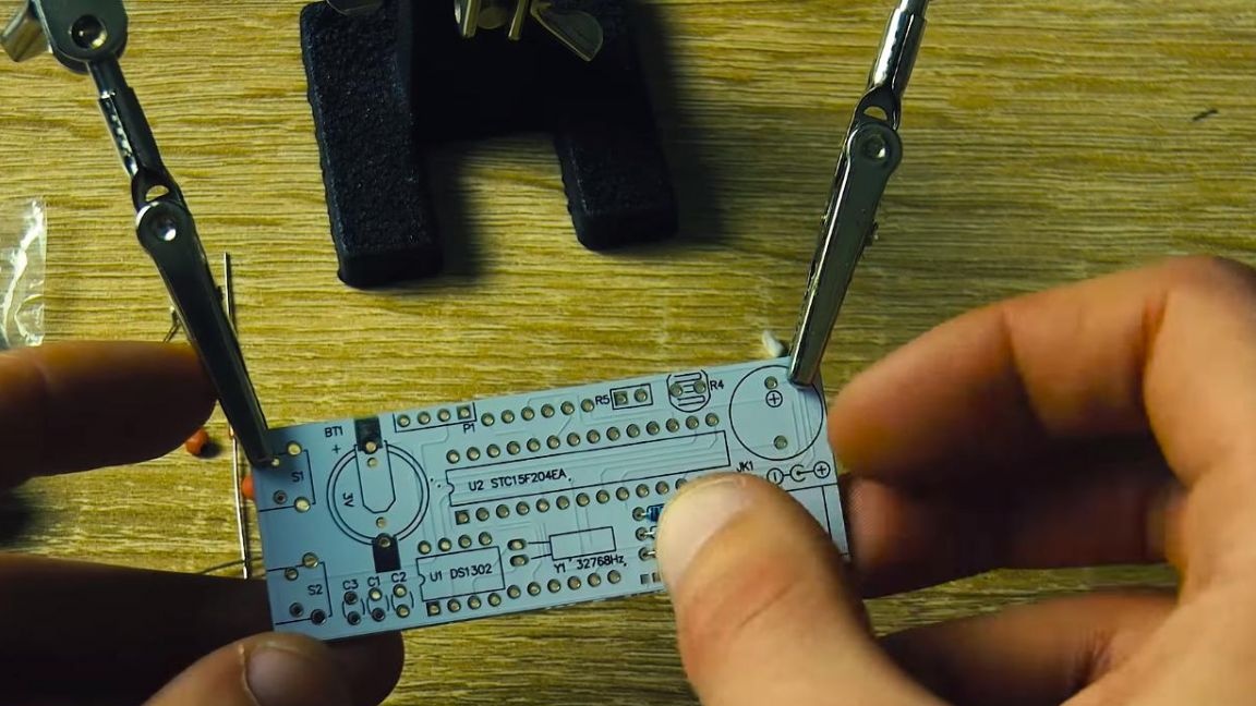
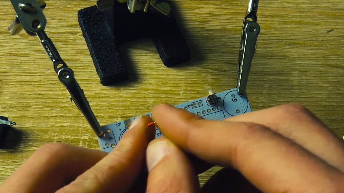
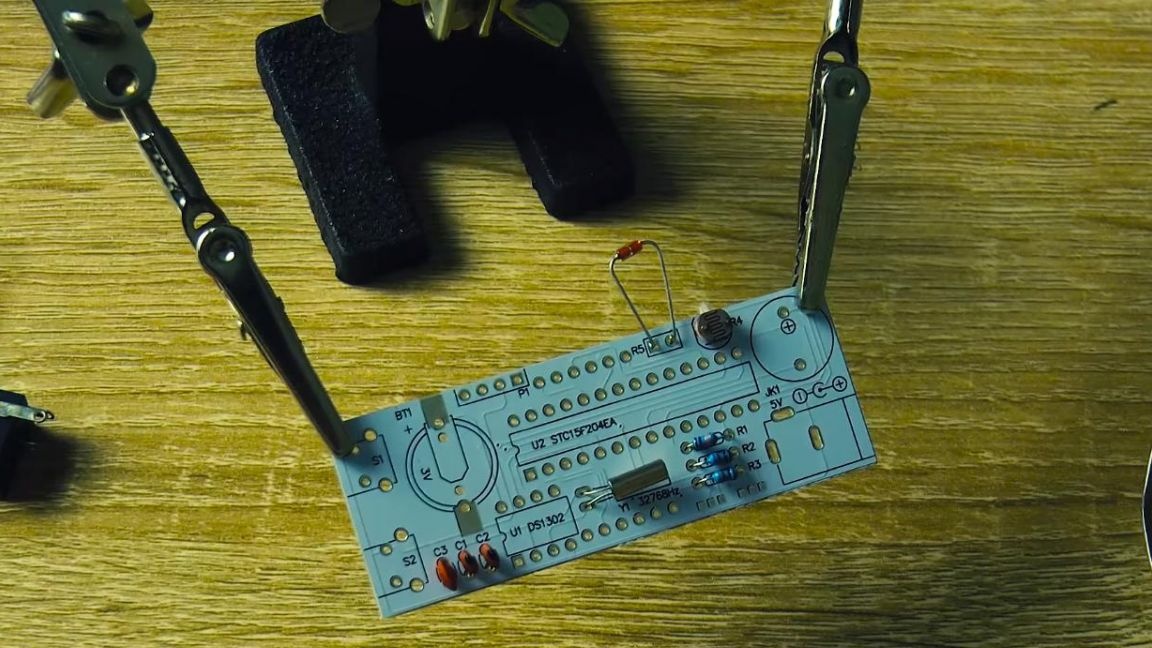
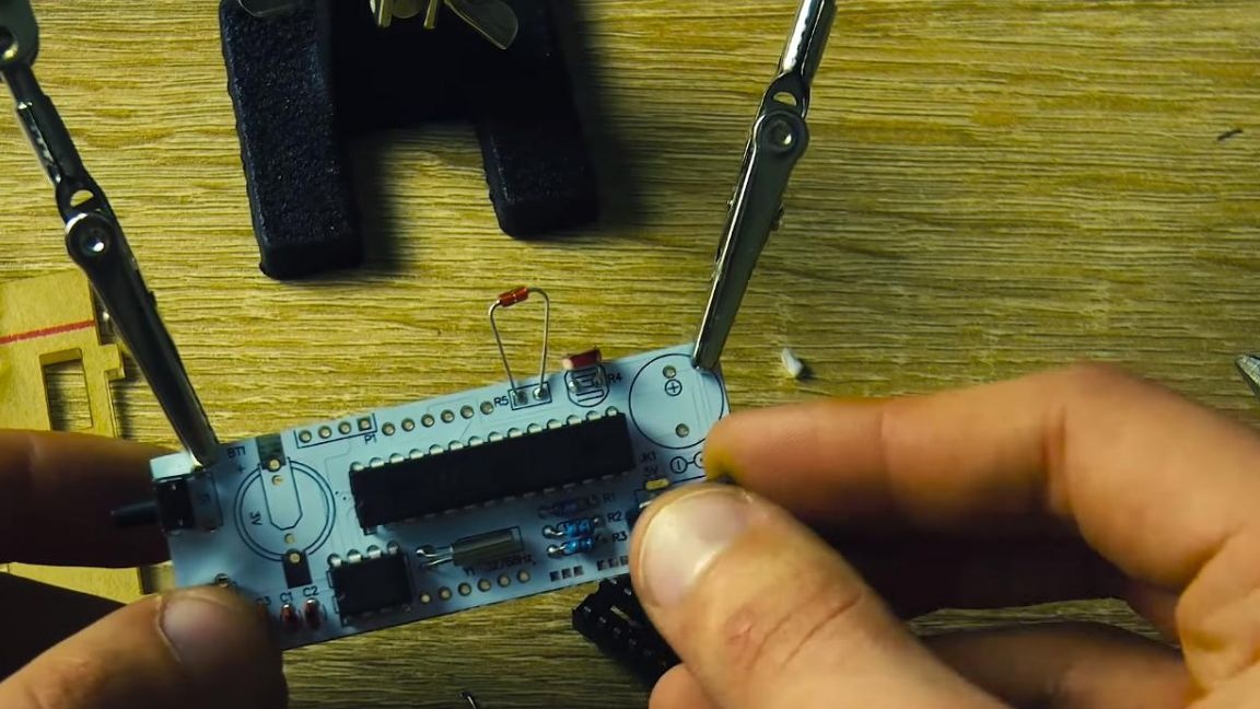
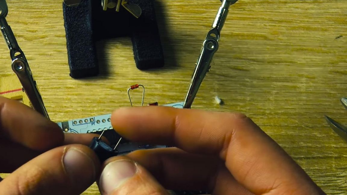
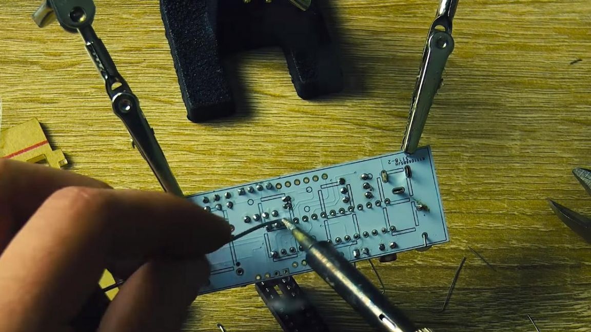
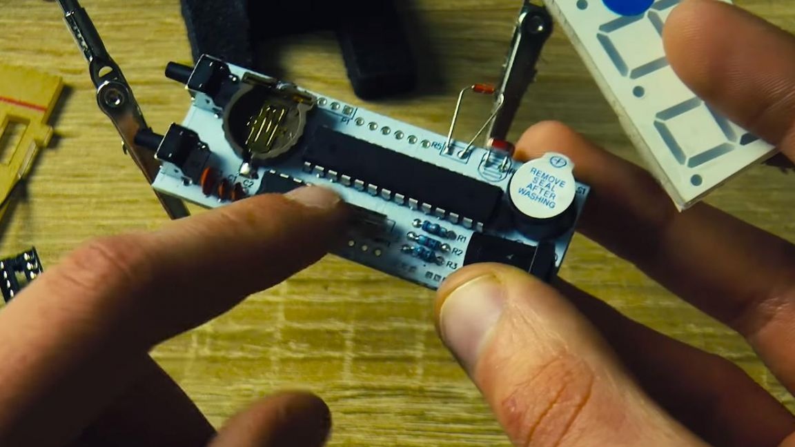
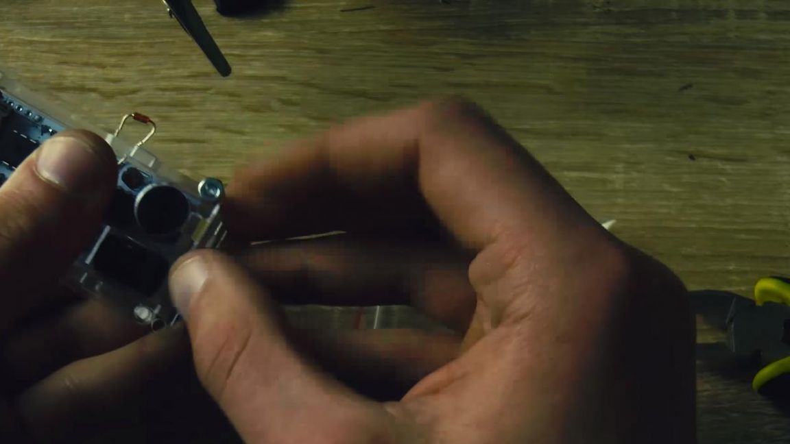
Now we insert the photo and the thermistor, the first can be installed close to the board, but the thermistor needs to be brought out a little outside the case so that the temperature measurement is as accurate as possible, for this we solder it, leaving long legs.
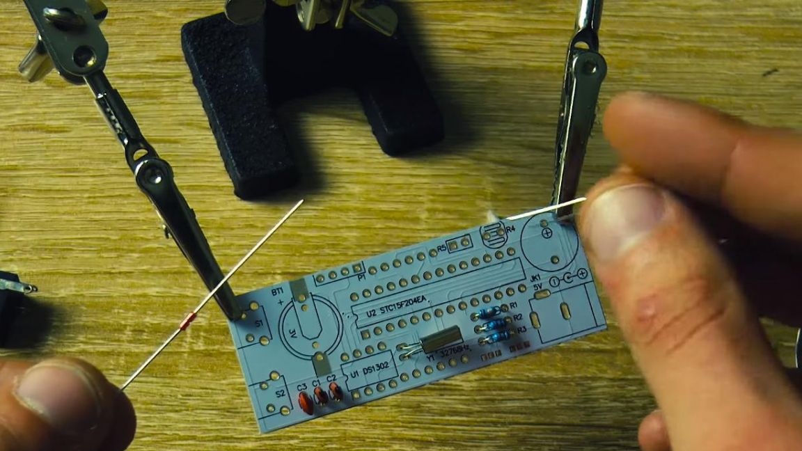
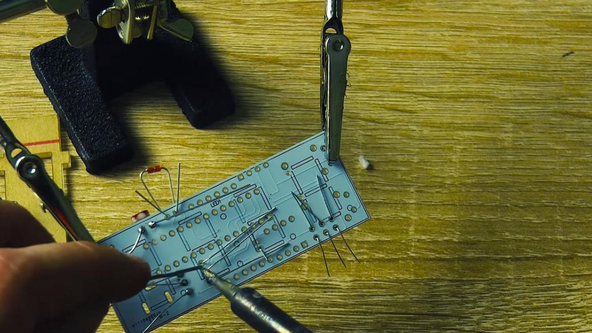
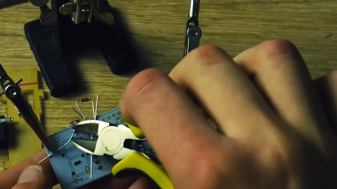
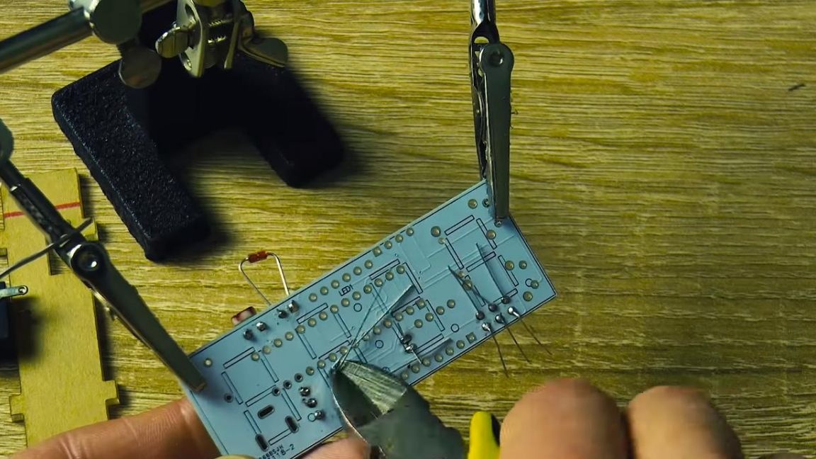
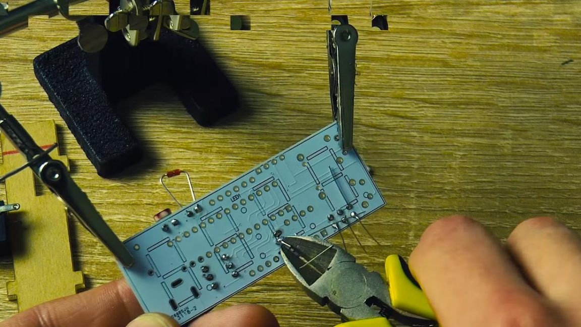
Next, solder the remaining components on the board, apply flux for better soldering. After soldering, we remove the extra parts of the terminals using side cutters. This method is good enough, but be careful, as you can delete the track itself, which will be difficult to restore.

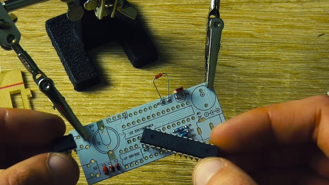
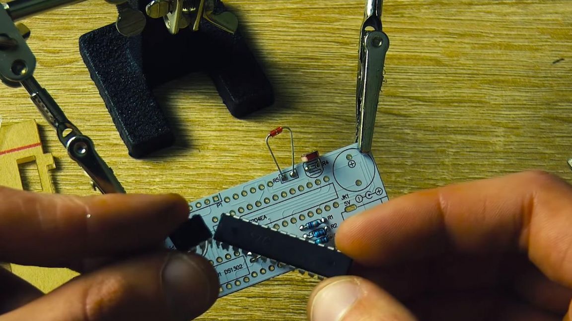
Step Four
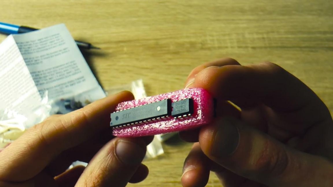
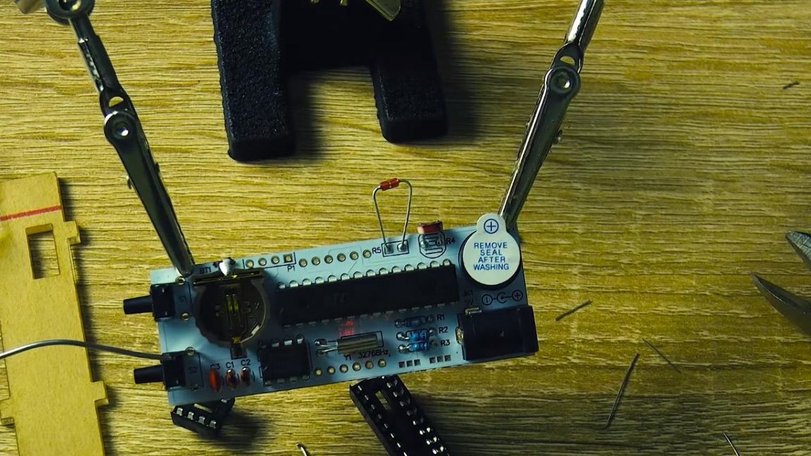
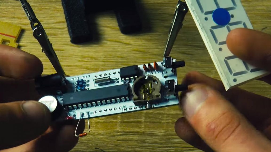
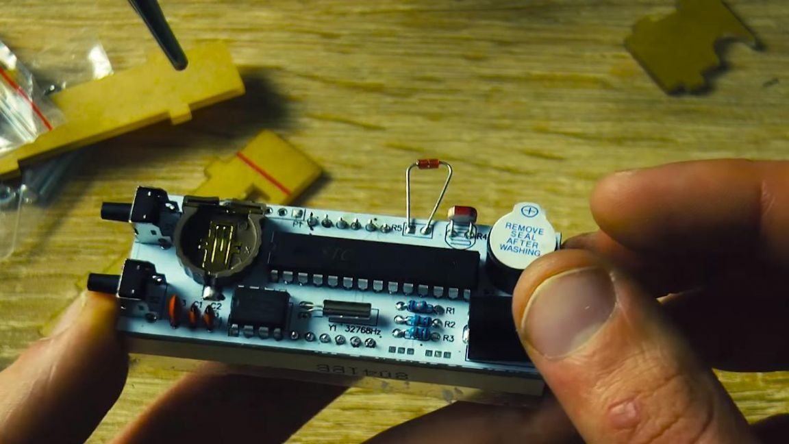
After that, we turn to the microcircuits, there are two of them, one has eight pins, the other 28. You can’t confuse one with the other, and for their proper installation you need to combine the key on the chip, which is made in the form of a semicircle or a dot with the key on the board , also on the board, the first contact is made in the form of a square.
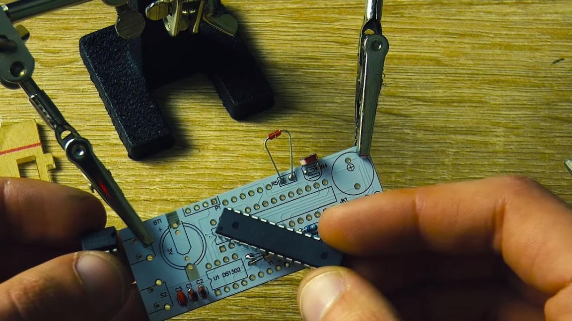
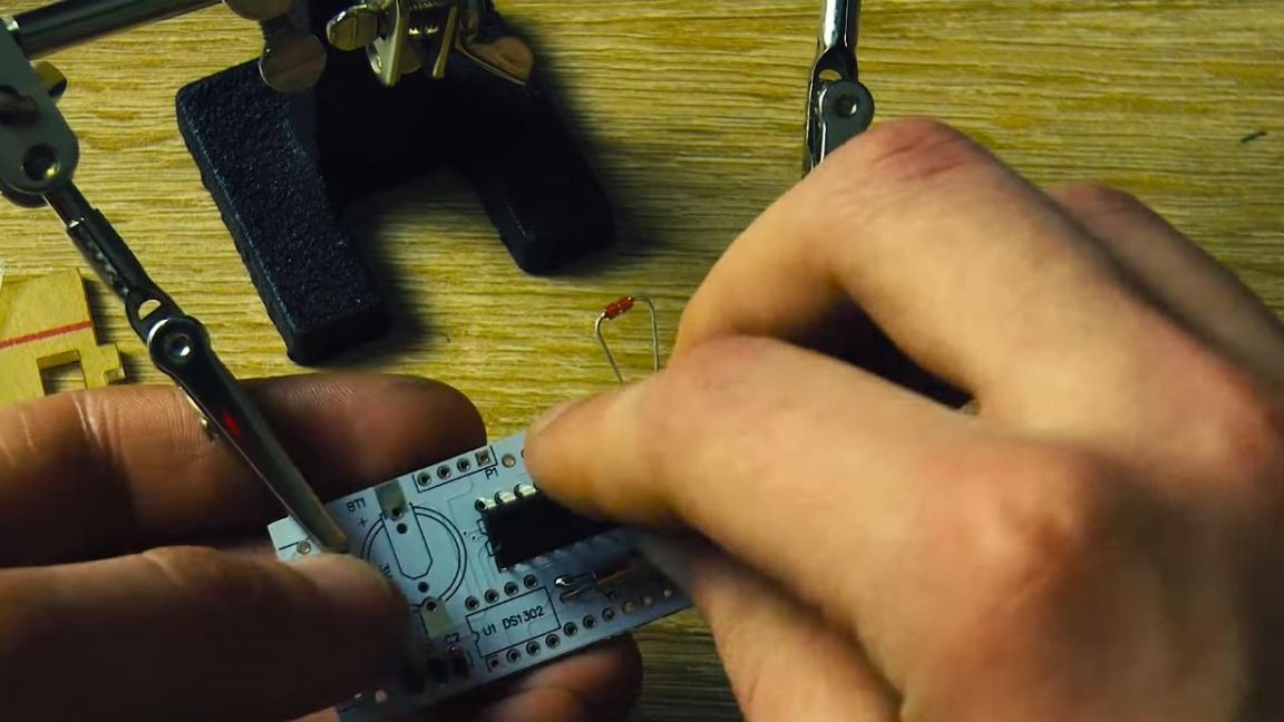


Similarly, we do with the second chip. In the kit there were two sockets for installing microcircuits, but to install them or not depends on you, since they can be soldered without it. When soldering without sockets, do not overheat the microcircuit, as they may fail, plus the nests are that the microcircuits from the soldering iron will not heat up, because they are installed after the soldering.
Step Five
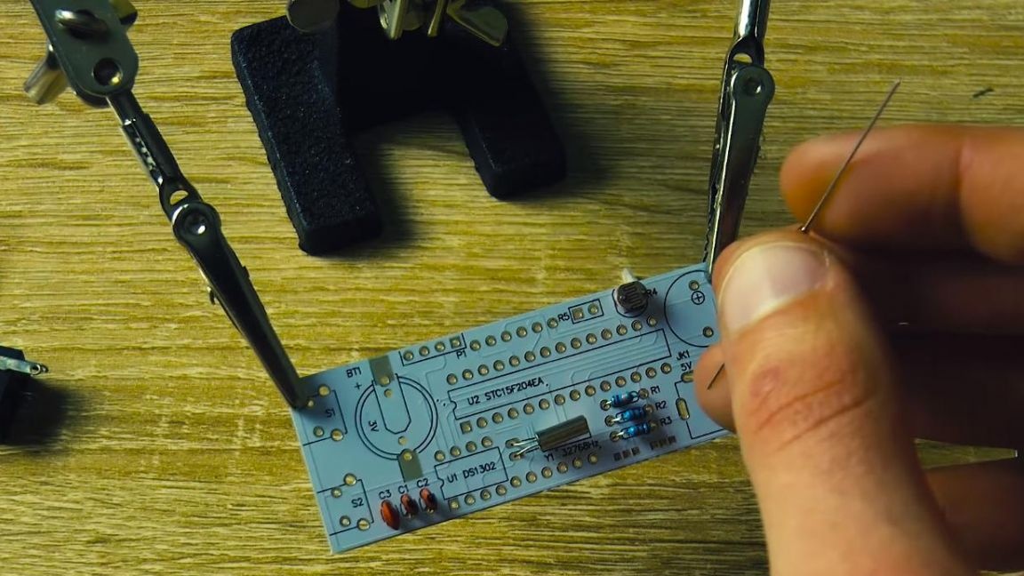
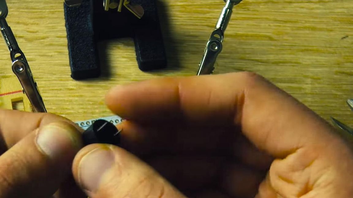
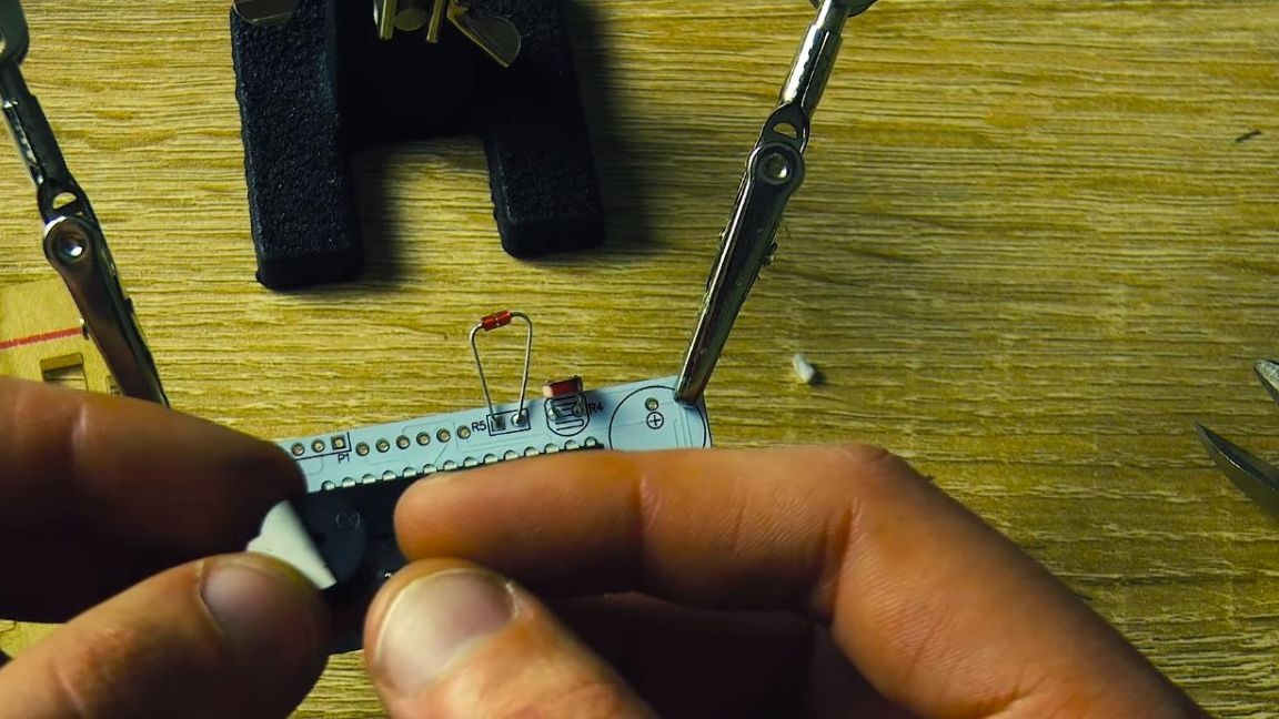
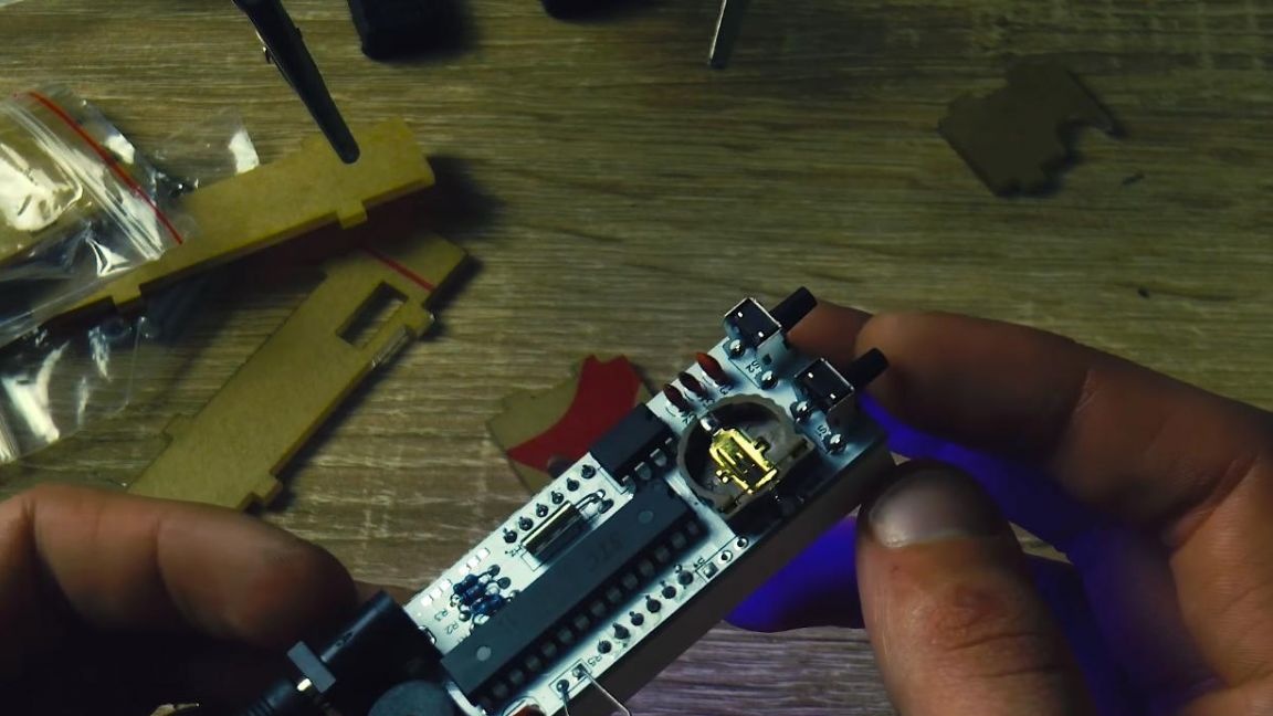
We put buttons on the board, which in the future will allow you to configure the clock.
Then we install a power socket and a tweeter, on its case a plus is indicated, on the side of which there is a positive terminal, also the polarity can be recognized by the length of the legs, long — plus, short — minus, and on the board itself there is a plus in a circle.
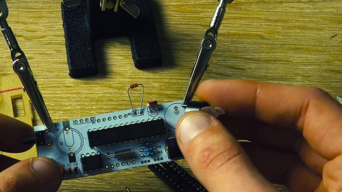
We solder the connector for the battery, which will continue the passage of time when disconnected from the power supply, after connecting the power, time will not be lost.
Step Six
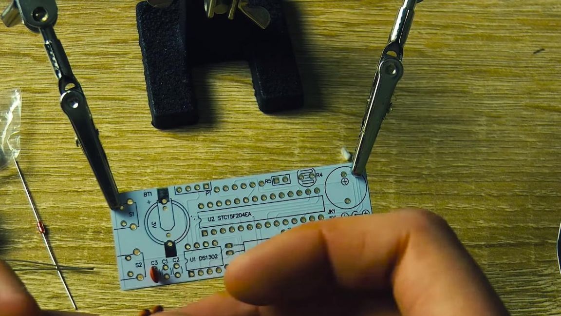
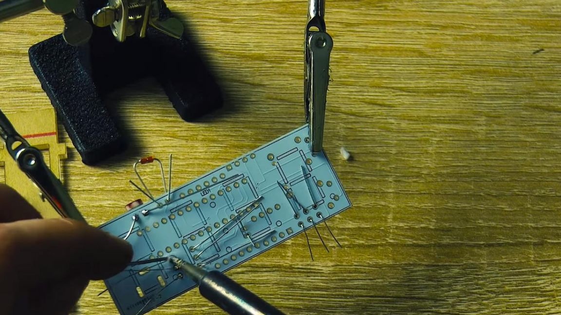
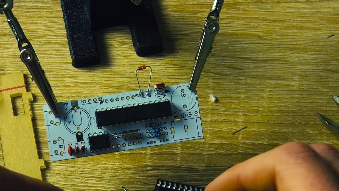
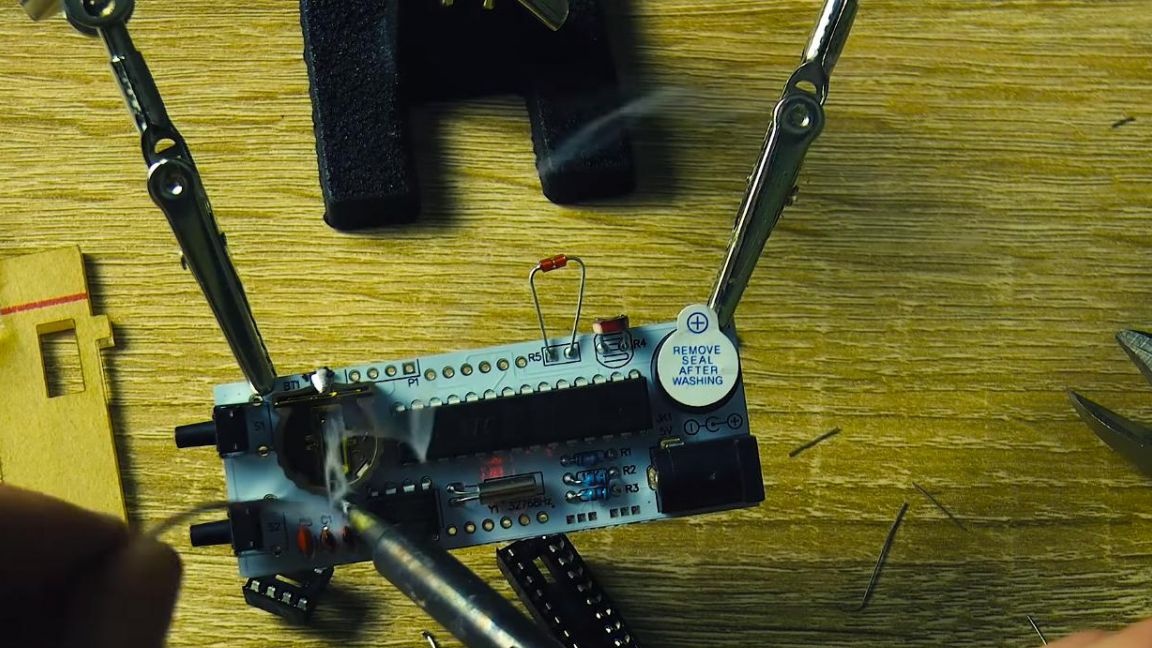
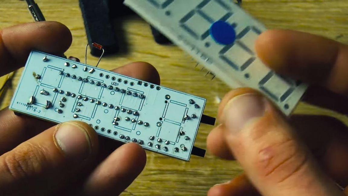
Now we solder all the conclusions of the radio components well, after applying the flux to the contacts.
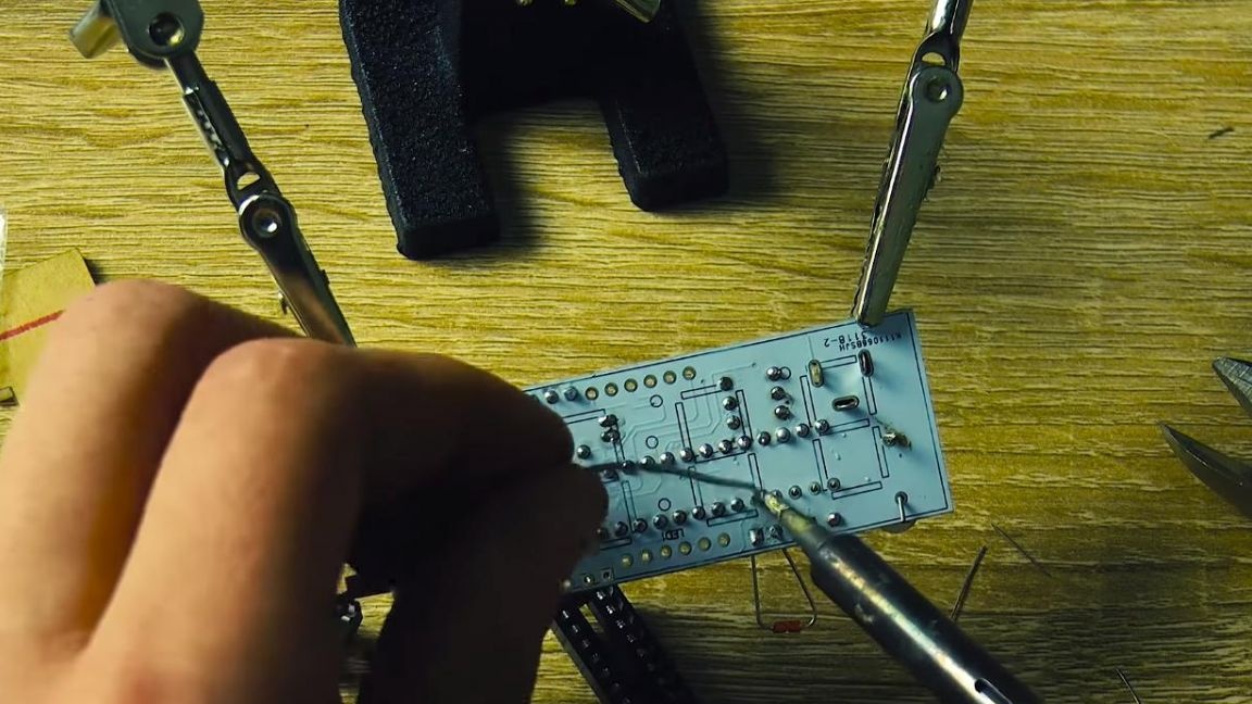
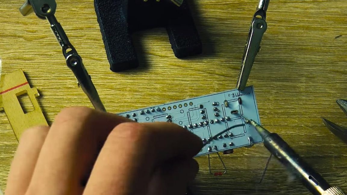

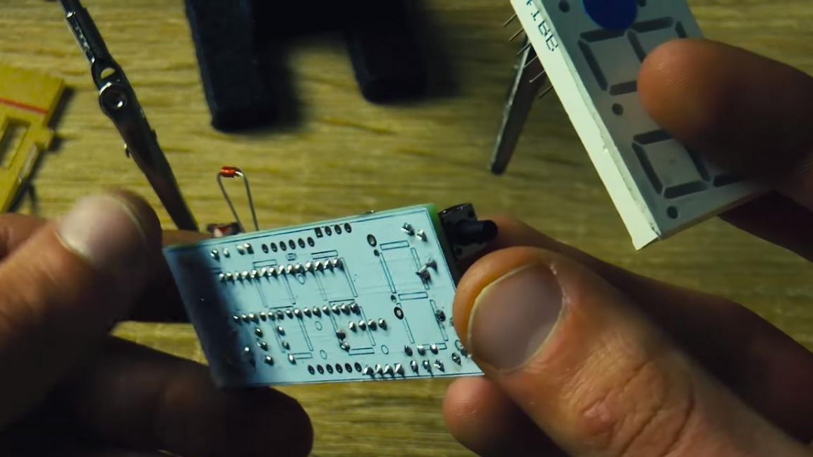
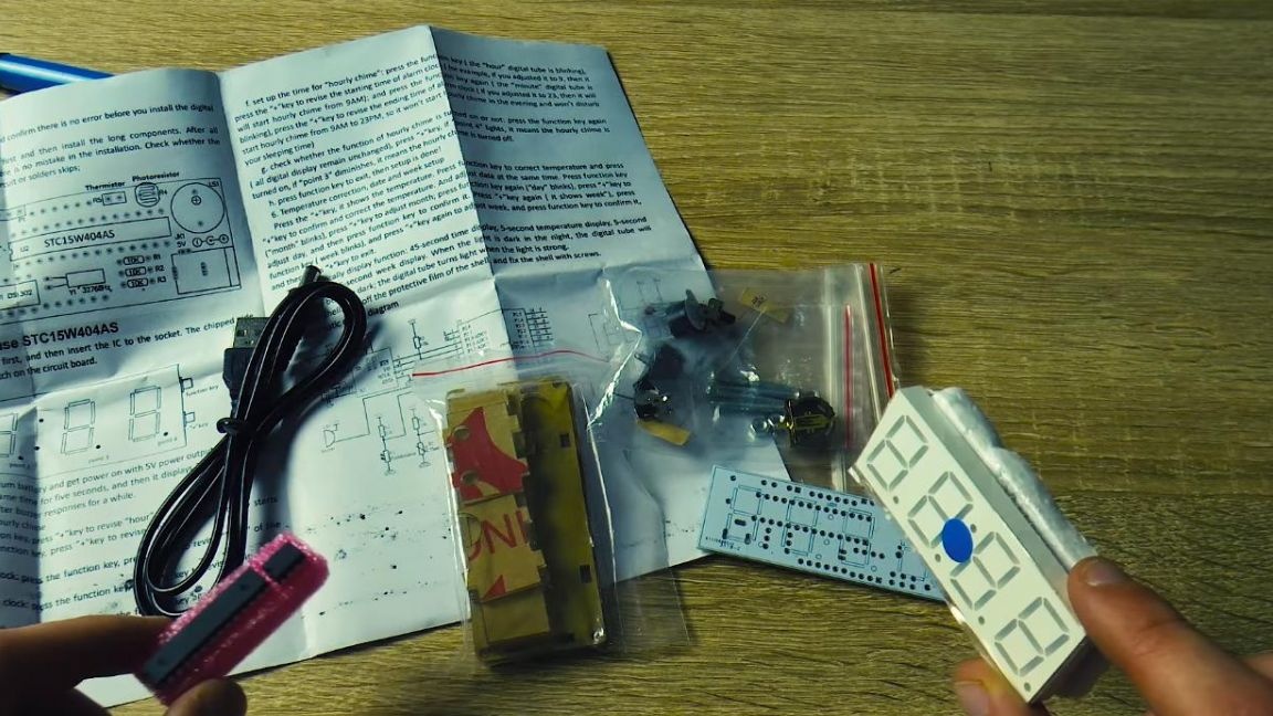
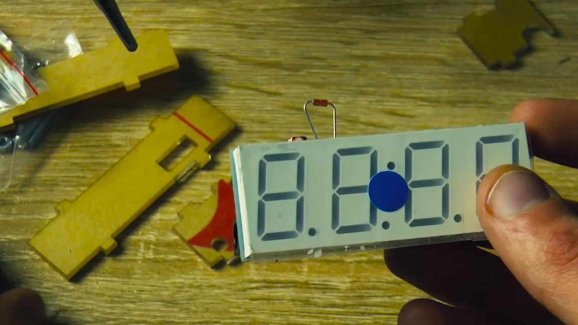
Of e almost all parts, it remains to solder the LED matrix. We install it in its rightful place and solder it.
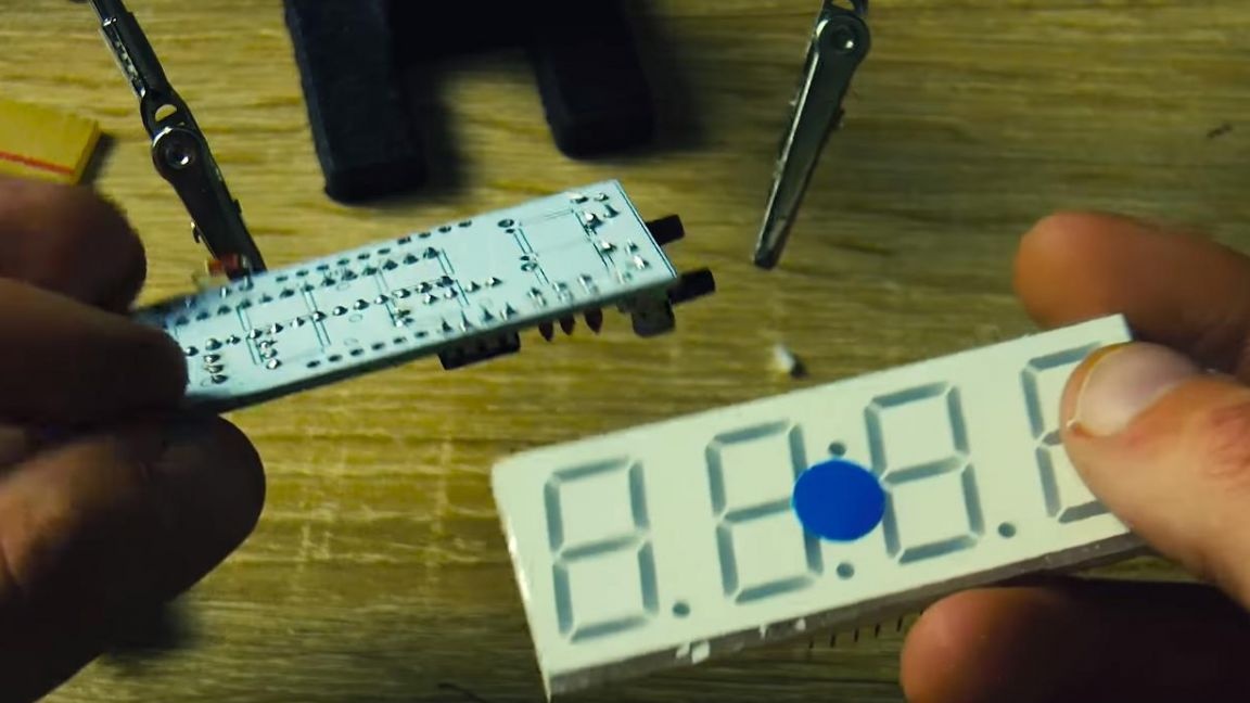
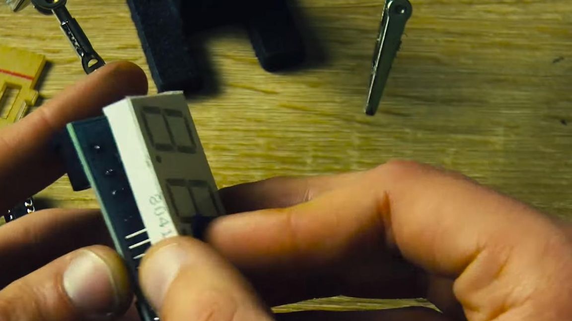
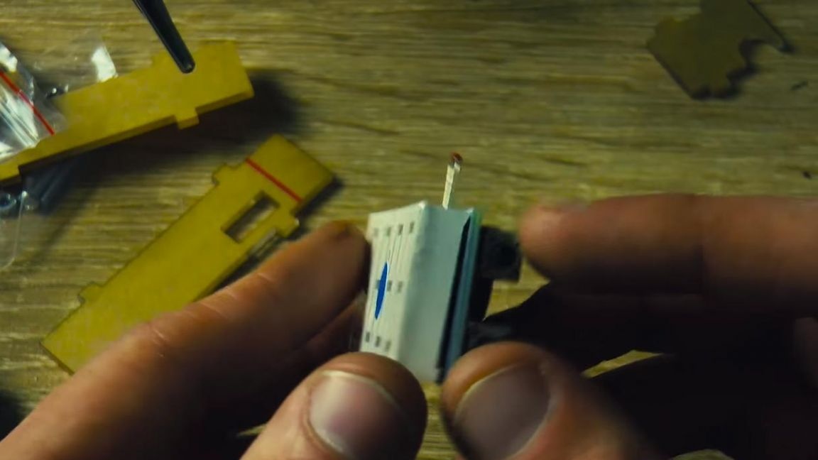
On this, the soldering iron can be turned off.
Seventh step.
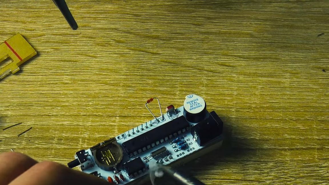
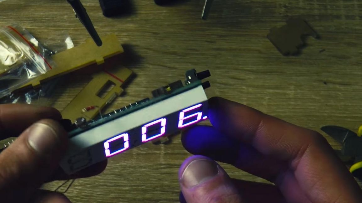
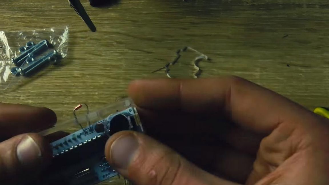
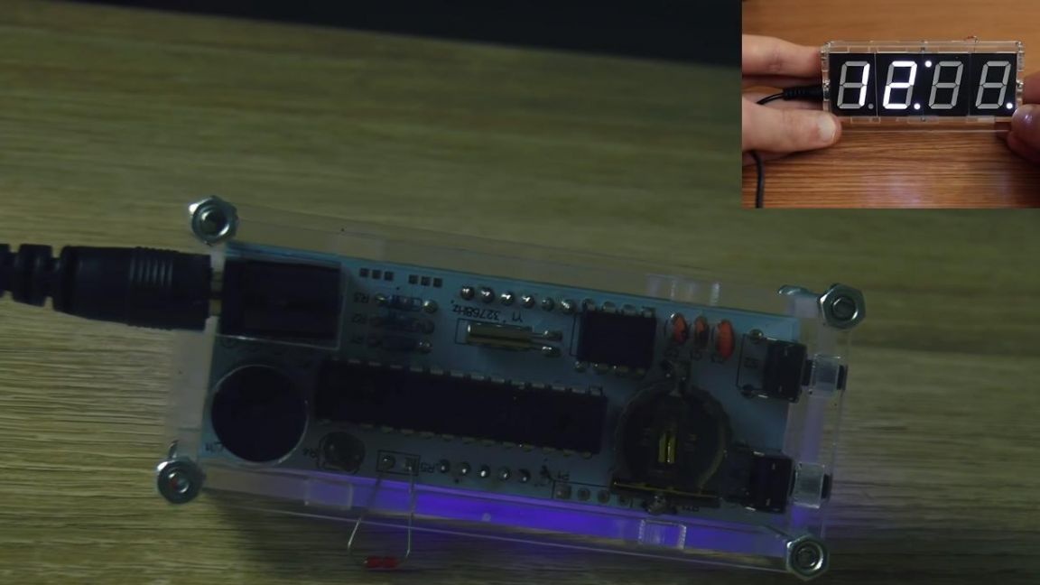
It's time to put all the stuffing in the case. Before installing in the case, we check the clock for operability, so as not to disassemble it with any error or malfunction.

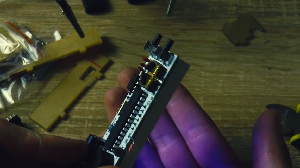
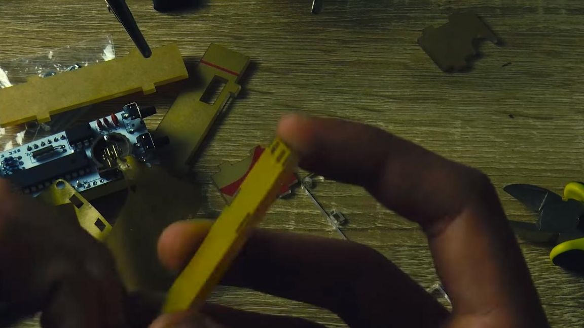
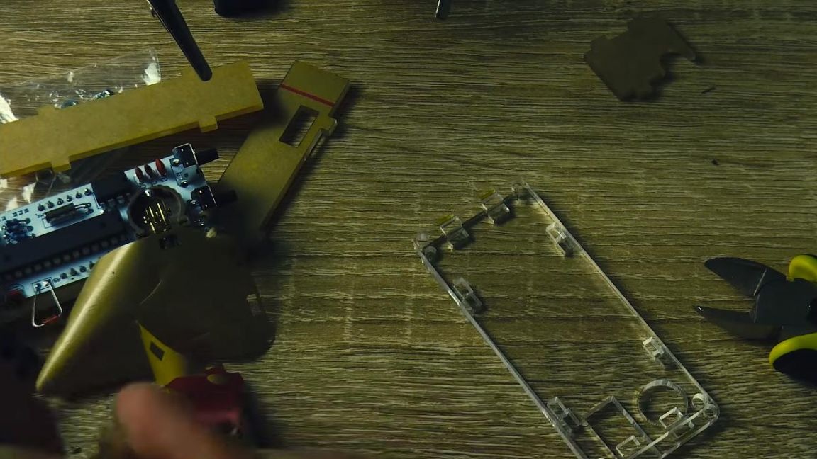
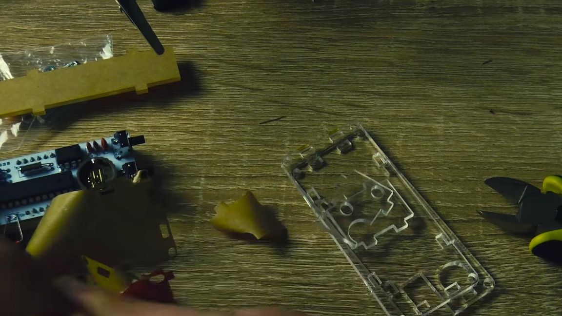
After we are convinced of the correct operation of the watch, we begin to remove protective films from plexiglass plates. They are fastened together with the help of special grooves and screws with nuts that pass through the housing.

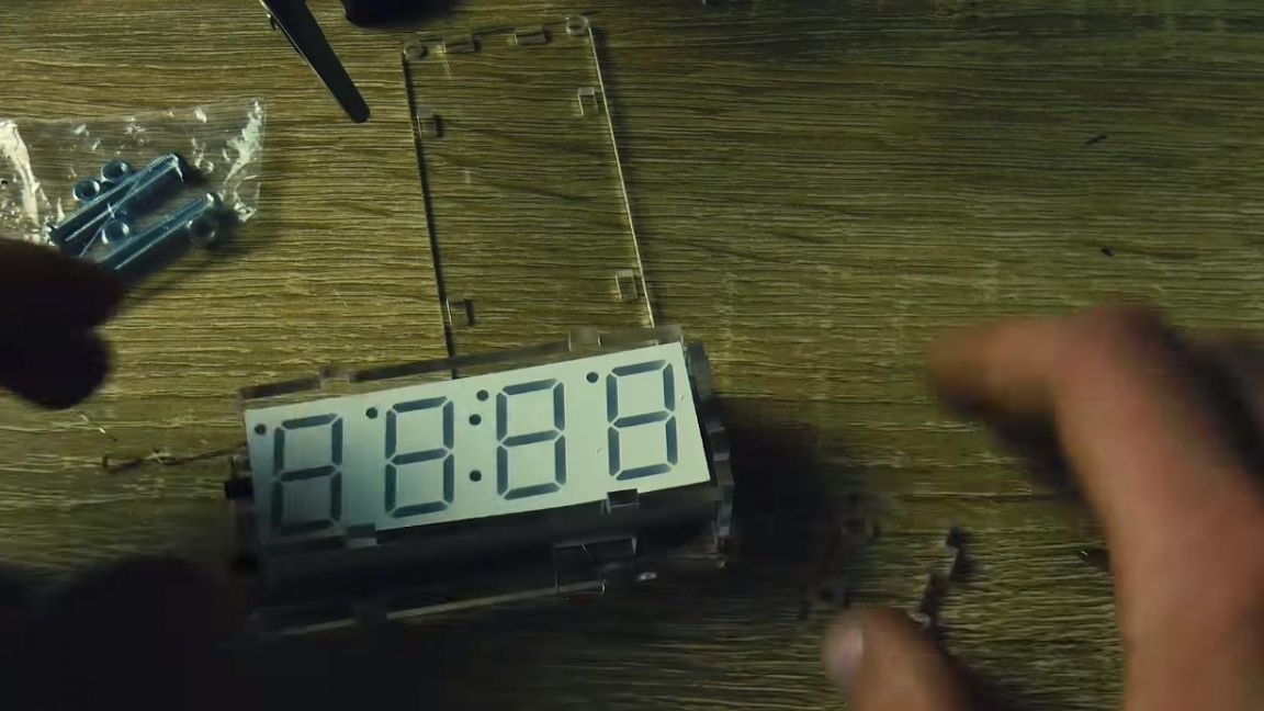
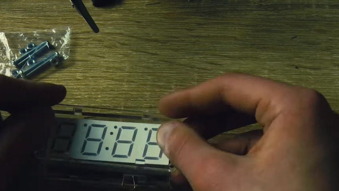
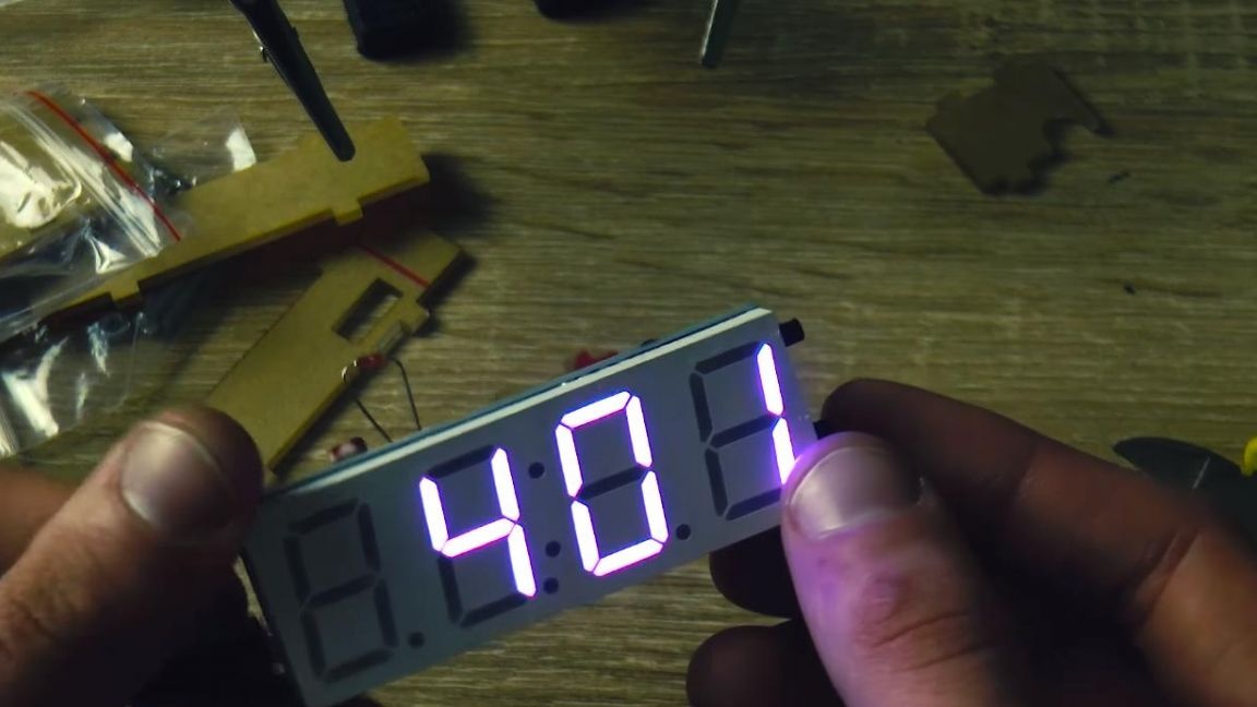
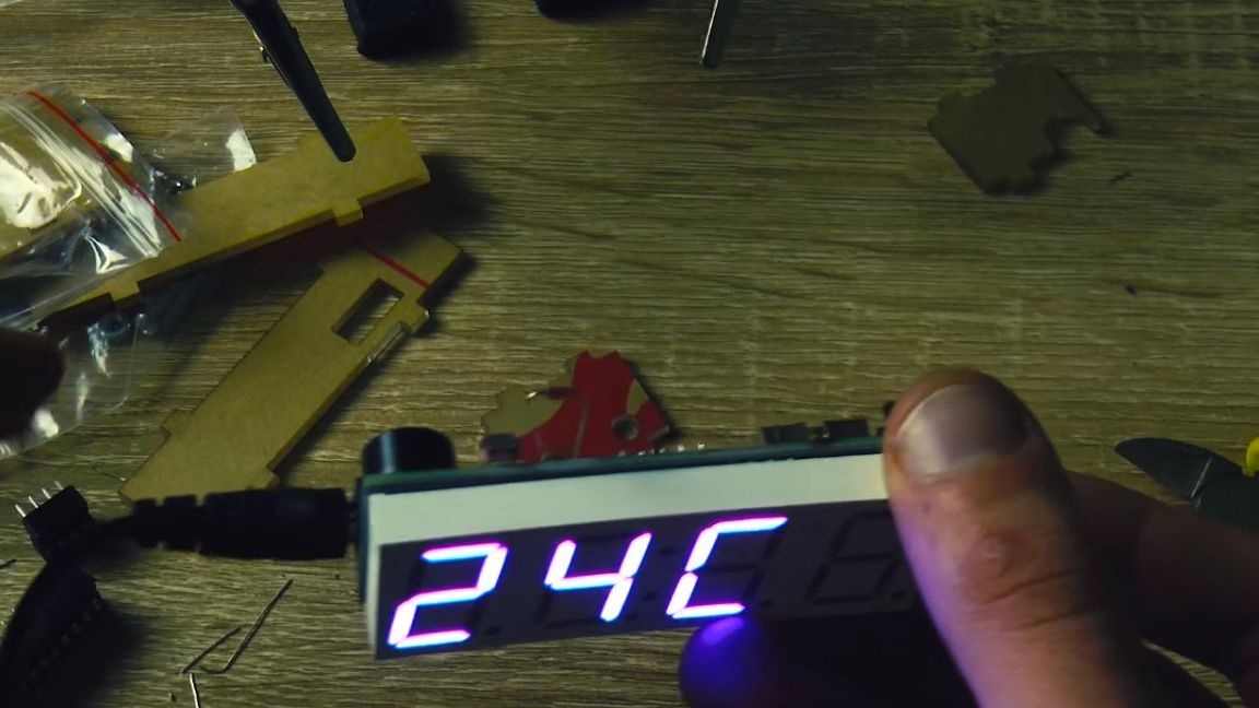
That's all, the digital LED clock is completely ready, we connect them to the power supply with a USB output and set the time.
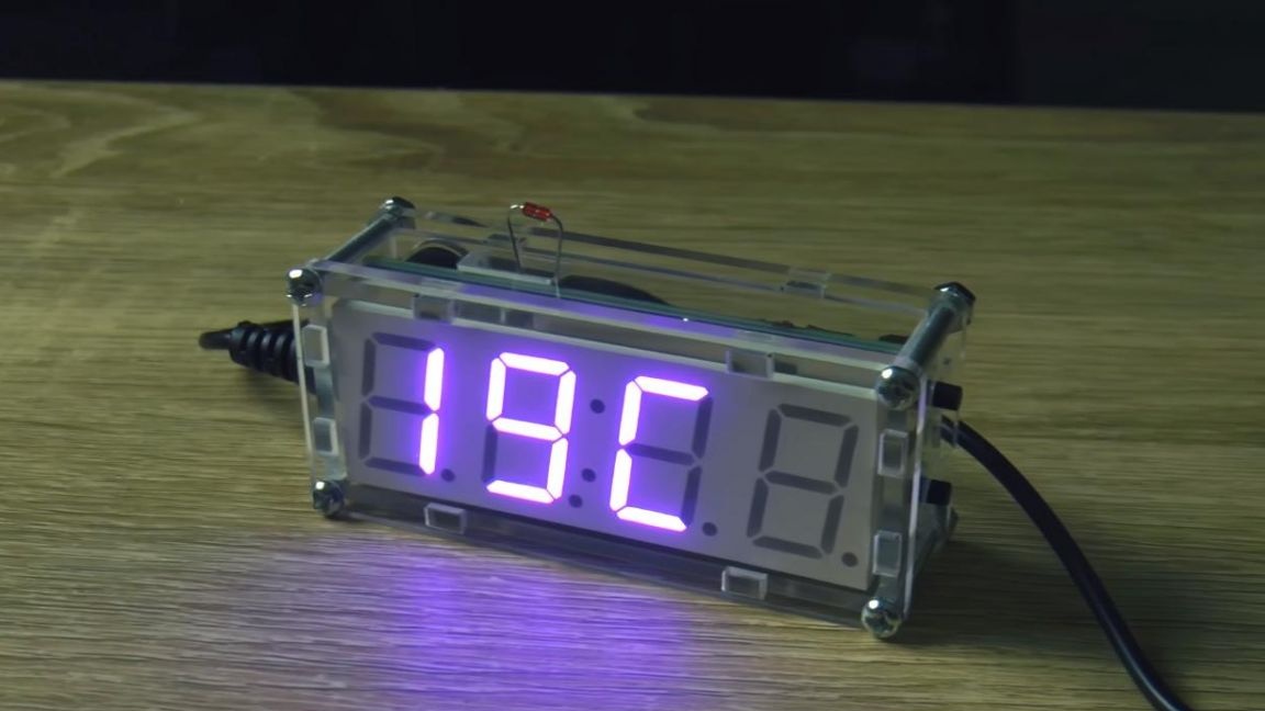
These watches look quite original, their transparent case looks unusual, and the thermistor brought out of the case allows you to determine the temperature in the room, which will definitely not be superfluous. They also have a convenient function, which is implemented using a photoresistor, when night falls, the LED matrix of the clock lowers the brightness and thereby does not blind the eyes.
That's all for me, thank you for your attention and creative success.