

The second, successful version of the carburetor device for a large tabletop glass blower. The first was the option
Carburetor device for glass blower, according to the classics scheme [1], but it turned out to be not too durable and during pressure tests it broke due to a factory defect. The current option, much simpler and more reliable, was recommended by my mentor, a wonderful craftsman, glassblower and astronomer, Yuri Nikolayevich Bondarenko. Such constructions have been working on his farm for a long time, periodically improving [2], so my version is a kind of quintessence of his developments.
Let me remind you - the goal of all these evolutions is to replace oxygen in a glass-blowing workshop. It is regrettable, but the last source of good, relatively fusible - not requiring oxygen blasting, blanks for glass-blowing - materials for neon advertising, were covered with a copper basin, it seems, together with the entire industry. They were replaced by LED strips. And glass tubes, which serve as the main blanks, are now offered for sale only relatively refractory. Requiring oxygen air blast additives. Oxygen is a very dangerous gas and not very convenient to use. When used in a workshop, it is necessary to fulfill significantly more stringent safety requirements, oxygen cylinders are designed for a pressure of 150 atm and a standard oxygen cylinder with a capacity of 40 l - it weighs about 75 kg, which does not allow it to be transported and loaded alone. Transportation of oxygen cylinders is subject to special requirements.
Gasoline vapors, by themselves, provide a flame temperature somewhat higher than even propane, not to mention natural gas, and in many cases, this is quite enough, however, a complete replacement of oxygen blast is ensured by adding a small amount of detonating gas from gas vapors electrolyzer.The original glass-blowing torch for these gases, with internal mixing and adjusting the shape of the torch, was designed by Yuri Nikolayevich Bondarenko, is used by him and is being improved. It will be discussed separately. By the way, these gases should be mixed in the burner and in no case should explosive gas be supplied to the tank with gasoline - this sharply increases the reaction time for regulation, and it is also dangerous.
In addition to the increased temperature of the torch, gasoline is safer compared to gas, since its vapor leaves the tank only when it is purged with air and getting into the room in quantities that are dangerous, in the sense of an explosion, is practically excluded. When a room with gas cylinders inside is ignited, it will have to be extinguished with an eye to their explosion, while gasoline in the tank will first boil, then hot, will flow into the fire, which is also not good, but there will definitely not be an explosion. The pleasant moments include the location of the adjusting valves - they are all (two) located on the carburetor, and not on the hot burner, which greatly simplifies their life. It should also be noted that the delivery of liquid fuel is easier than gas in cylinders, which in the case of a remote location for the workshop is a significant advantage.
So, gasoline vapors. In principle, for using exclusively gasoline vapors in the burner, the carburetor vessel can be very unstable - the pressure there is almost atmospheric, and from the breakthrough of the flame, a simple packing with a copper “hook” or a copper mesh protects quite reliably. The practice of dentists and jewelers, where such burners are traditionally used, is of great duration.
Let me remind you - a flash of flame inside the burner and then, with luck, depends on, and it depends on many factors, but primarily on the composition of the gas. The highest propagation rate of hydrogen in a mixture with oxygen [3]. The propagation speed also strongly depends on the temperature of the mixture; this is the basis for the method of preventing the penetration of the flame into the burner - a copper mesh or “deep” holes. The flame, passing through such a grid, is cooled so much that it goes out. There is a concept - This is the maximum diameter of the "deep" holes that can perform a flame arrestor function, and it is different for different gases. For example, for gasoline vapors in the air, the flame propagation velocity of which is small, the limiting hole is ~ 0.9 ... 1 mm, but as soon as oxygen or explosive gas penetrates the system, which significantly increase the flame propagation velocity, the holes in the protective “mesh” will have to be made substantially smaller. The maximum diameter of the holes, for example, for explosive gas, ~ 0.3 mm, which represents some difficulty in the manufacture and operation.
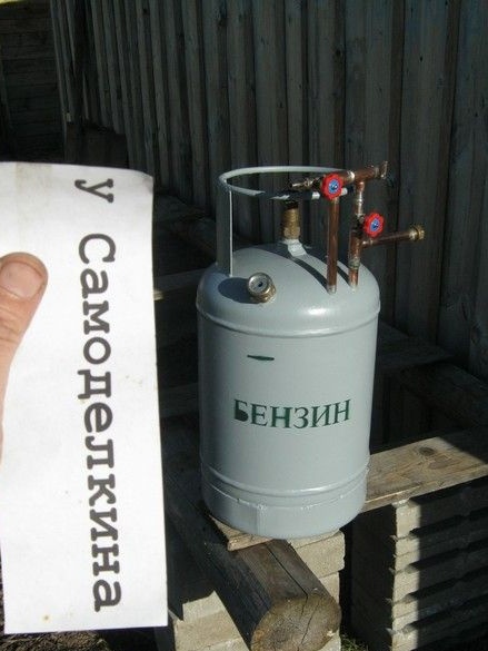
It is clear that for the safe operation of gas-flame equipment using explosive gas, it is worth paying increased attention to its reliability. The described design of the carburetor provides it fully. The use of a propane household cylinder as a container with a test pressure of 2.5 MPa allows the device to withstand blasting without damage.
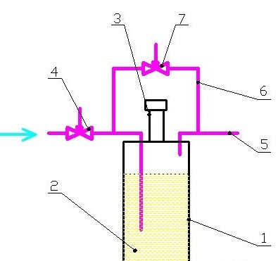
Carburetor circuit. Where 1 is a tank, 2 is gasoline, 3 is a filler neck with a cover, 4 is an air supply control valve, 5 is an outlet pipe, 6 is a bypass, 7 is a bypass tap.
General considerations.
High capacity durability. Among the suitable ones, the candidacy of a carbon dioxide fire extinguisher of 5 l capacity was also considered. Essentially the same cylinder, with comparable maximum pressure. However, the propane cylinder is much more convenient structurally - a wide bottom with a special side, which eliminates tipping over relatively smooth surfaces, the fencing-handle on cylinders of small capacity, allows you to conveniently carry the device, and can also be used in the design of external additional elements, such as an attachment point, for example . Moreover, the cylinder is much wider - the surface of fuel evaporation is significant and in some cases, the air supply pipe may not be immersed in it.
Fuel tank heating - not applicable.On the one hand, heating can serve for more complete evaporation of fuel, however, in addition to this, along with a fuel tank, a metal flexible hose should also be heated, which leads the gas to the burner. Otherwise, volatile fuels can condense in the cold hose, and accumulate, splash out into the burner. On the other hand, heating can compensate for the cooling of the fuel during its active evaporation. The lack of heating simplifies the design and operation of the device. Full use of fuel in the workshop is achieved by its consistent use in the carburetor, then in the washing of the electrolyzer [2]. Non-volatile fuel residues can be used to ignite solid fuels or as a solvent. The cooling of the fuel by evaporation can be easily compensated by its relatively large mass.
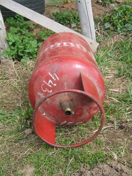
Tank capacity - Yuri Nikolaevich, in his practice, first used standard propane cylinders with a capacity of 5 l, however, using a large glass-blowing torch of his own design, when switching it from a “needle” flame to a large one, as a result of a sharp increase in evaporation, the fuel cooled, evaporation fell, which created inconvenience in work. His last modernization is an increased capacity, cut from a large cylinder. The middle is cut, the top and bottom are welded. The capacity of the vessel is about 10 liters. In this case, the volume free from fuel is 3 ... 5 l, the larger leads to the fact that changing the shape of the torch, we obtain a delayed reaction and the composition of the mixture, from which the burner can go out. The increased fuel volume, quite effectively compensates for local cooling during strong evaporation. Here, it will be appropriate to give recommendations on the level of the air tube. The author recommends immersing the air tube in the fuel 10 ... 15 cm or less, and tighten it tightly, creating resistance to the air flow, so that the bypass works more efficiently. The hole at the end of the tube is the only one, with a diameter of 1 mm. Sometimes it’s a nozzle at the end of the tube, but a thin, compressed carnation pulled out afterwards also works.
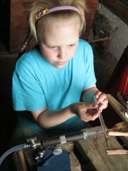
Working with a simplified gas generator presupposes maintaining such volatility (the ratio of running and fresh gasoline) of the fuel mixture in the tank, in which you can get a stoichiometric (based on chemistry - for so many fuel molecules, so many oxygen molecules) or a close composition of combustible gas mixtures. The flame will be the hottest. In practice, it looks like topping up a liter (two in winter) of fresh gasoline into the tank when the flame on the burner deteriorates. If necessary, the excess spent fuel is pre-cast.
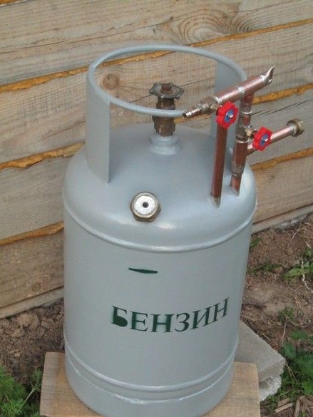
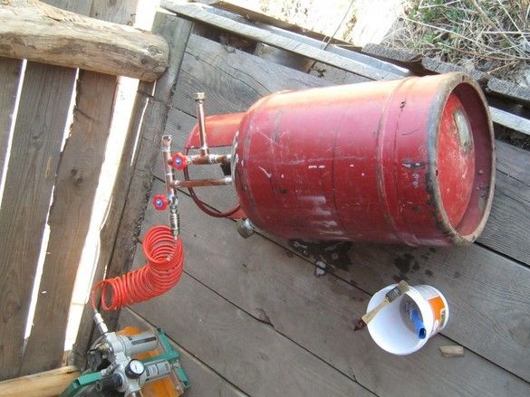
So. It was decided to use a propane cylinder with a capacity of 27 liters without alteration as a vessel. It is a bit big, but I really didn’t want to digest it. Height, it is quite possible to place it under the table, with some margin on the tube-taps sticking up. It seems that the only drawback apart from the size will be the large initial amount of fuel required for refueling.
It was decided to make the filling neck from above, closer to the cylindrical part, so that the cylinder did not need to be tilted too much to drain the gasoline.
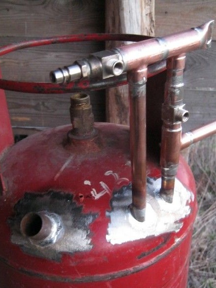
The air supply and exhaust gas pipes, it was also decided to pass through the cylinder body. A full-time crane is thus not involved, which is not bad - dismantling it is rather laborious.
Tools, equipment.
All connections were made by soldering - you need a small gas burner. Set of bench tools. Medium size abrasive sanding pad for sanding soldering spots. For accurate cutting of copper tubes, it is convenient to use an end pendulum saw, or a standard cutter with a roller.
Materials
In addition to the details from the copper pipeline, two needle faucets were used, copper pipes 15mm and 18mm in diameter. Tin-copper solder No. 3, flux to it. For painting - LMB, dishes, brush.
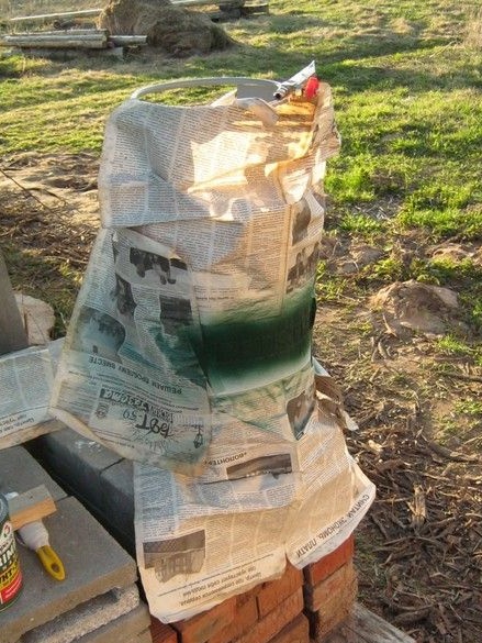
An open empty cylinder was sent for three or four days in the sun - to evaporate the remnants of the odorant (a strongly smelling substance added to the gas for ease of detection).
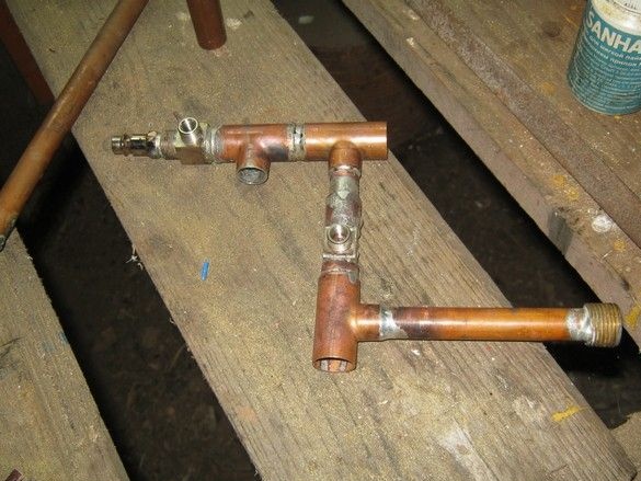
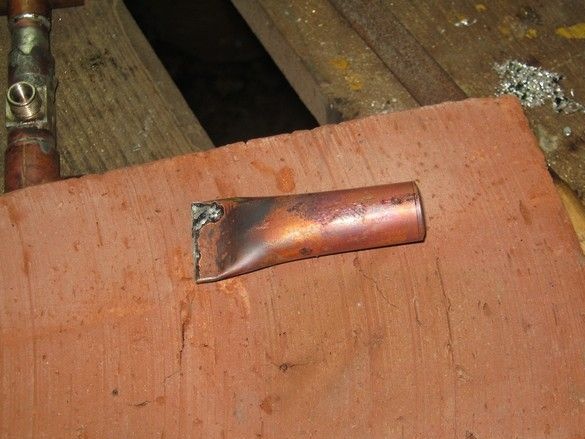
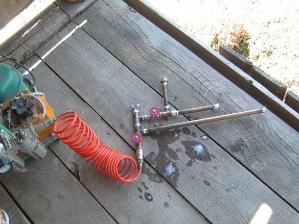
In the meantime, he began to manufacture the "additional" parts - tubes, taps.From the dismantled remnants of the previous, samovar. In addition, the communications turned out to be very compact, ready-made components and parts were used - things went pretty quickly. To increase the survivability of the apparatus, all rations were made “lapped”, as such, I considered compounds whose edges overlap, at least by 3 ... 4 mm. There was no standard plug for the "collector" - flattened and sealed a piece of a suitable tube. Previously, it should be annealed, cleaned from the inside and apply flux.
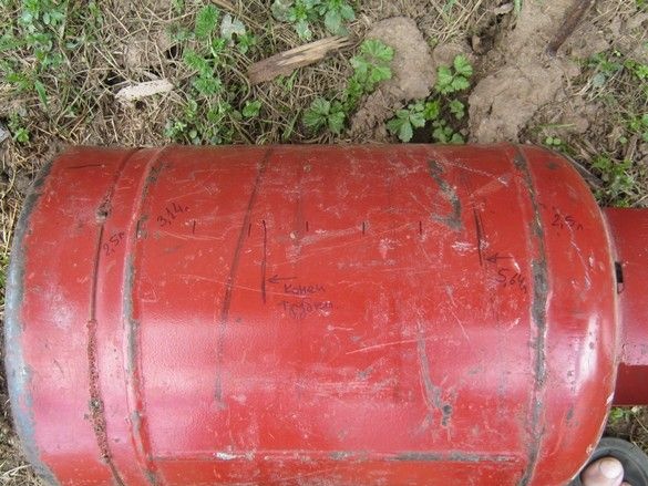
Marked on the cylinder the required level of gasoline, respectively, the length of the air tube. I proceeded from considerations - a five-liter gas cylinder, consists only of a “bottom” and a “cover”. Accordingly, the capacity of each of them is -2.5 l. The rest is clear.
He dubbed the copper part, plugged the ends of the tubes with soldering, checked for leaks with soapy water - beauty, can withstand as much as the samovars could not even dream of. The compressor used [url = https: //homediy.washerhouse.com/en/9842-vozdushnyy-kompressor-dlya-melkoy-pokraski-iz-starogo-holodilnika.html] home-made, based on the refrigerator [/ leech].
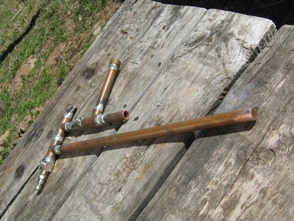
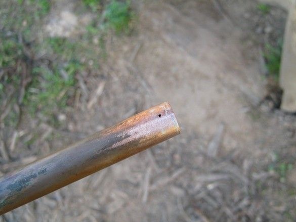
He clarified the length of the tubes in place, drowned out the soldering air, drilled a hole 1 mm in diameter at the end.
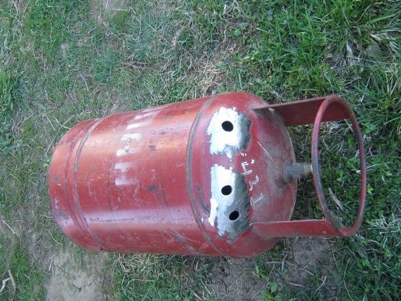
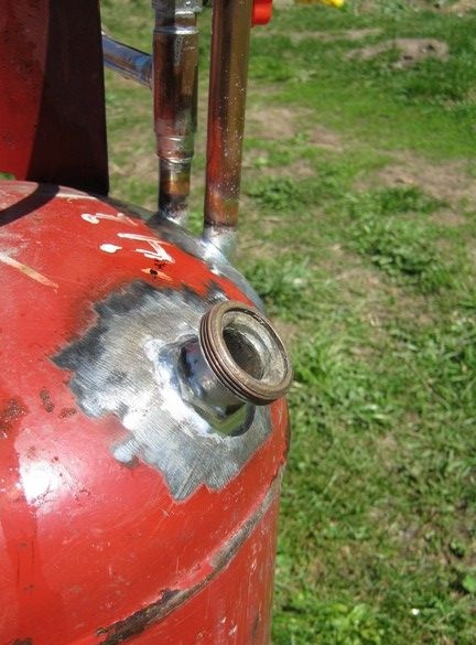
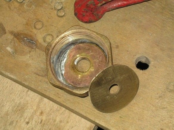
I marked the holes on the bottle with an alcohol felt-tip pen, drilled 10 mm holes (a small round file crawls through). I drilled a puncher with a nozzle - a drill chuck, very convenient - powerful, low revs. After boring and adjusting the holes, the rations on the container were cleaned with a small “grinder” on the tubes with a sandpaper. Flux, soldering, washing of residual flux. Initially, a 3/4 "pipe segment with a thread and a plug was used as the filler neck, but its thin end edges did not allow the tank to be hermetically sealed. I did not realize right away that I had to replace the brass neck from the same samovars. This edge is wider, in the cork made another additional brass gasket between the rubber band and the cover so that the rubber did not wrinkle when twisting. Through the hole you can see how it works. There were already holes in the blanks - there were no solid glands of suitable thickness.
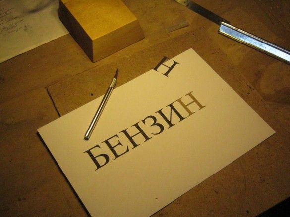
After installation and washing of the flux residues, I checked the device for leaks, and "little things" began - painting, and other marafet. He painted with primer-enamel on rust, in two layers. For impressiveness, I made an inscription through a stencil, a dash below the filling neck - the recommended fuel level.
Tests Before refueling, the device should be rinsed inside with several small portions of gasoline to wash off sticky dirty on the walls. The outlet pipe is loosely packed with copper “tangle”. The resulting gas was powered by a small tabletop glass blower. Its hollow body is also stuffed with a thin copper tangled wire - here, it is not only a protection against flame penetration, but also a gas flow damper. The fuel in the tank is 5 ... 7 liters, more has not been accumulated yet, but even so much fresh gasoline is enough for the burner to work. Despite the fact that the air tube is not immersed in fuel, evaporation from the surface is sufficient.
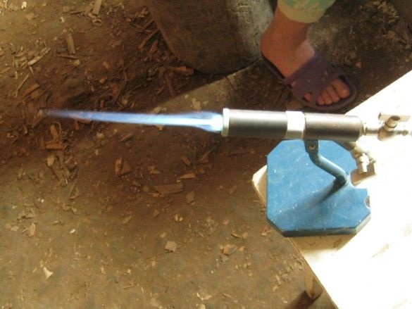
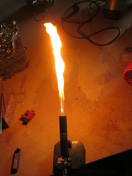
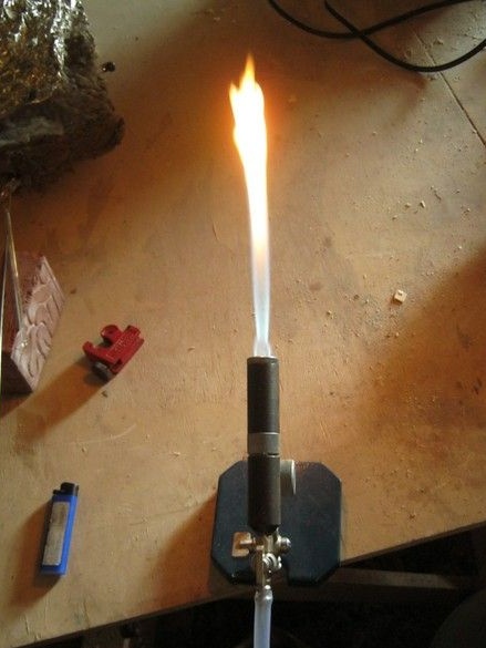
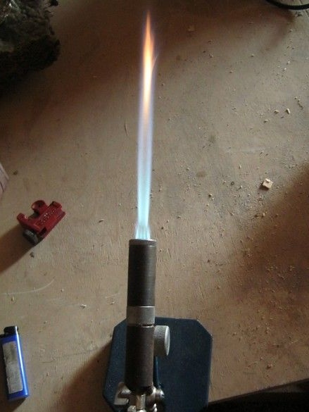
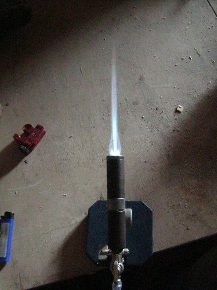
Finally, a photo of a burner with different flame settings, depending on the quality (saturation of gasoline vapor) of the working mixture, is an illustration of the bypass operation. In the first photo, his cock is completely closed - the concentration of gasoline vapor in the combustible mixture is maximum. Incomplete combustion (lack of oxygen) produces hydrocarbon residues that decompose to form carbon black. It is these smallest particles, repenting, give the flame a bright orange color. Later, when the bypass valve is opened, the mixture becomes leaner, the orange glow decreases, the shape of the torch more and more resembles a needle.
Used Books.
1. Veselovsky S.F. Glassblowing business. 1952
2. Bondarenko Yu.N. Laboratory technology. Production of gas discharge light sources
for laboratory purposes and much more.
3. Beshagin S.P.Fire equipment in electric vacuum production. Moscow. 1967