
In this article, SVIATOSLAV WOLF will show you how to vape yourself. The body of the structure will be created of plastic on a 3D printer.
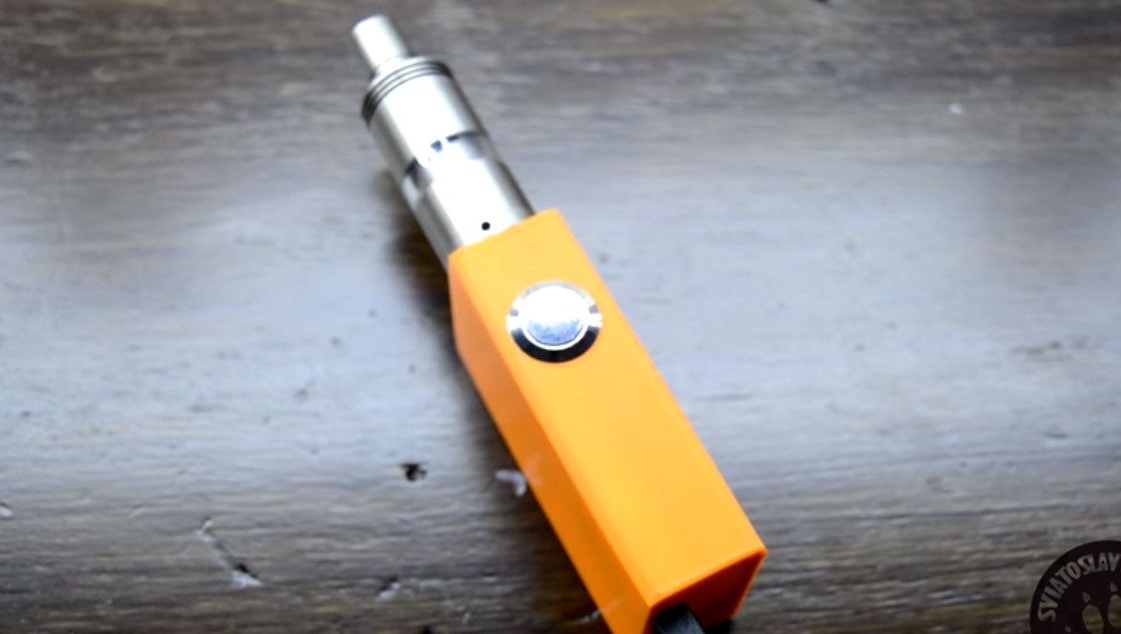
The vape will be small, compact, and very easy to manufacture. And most importantly, it will be stylish.
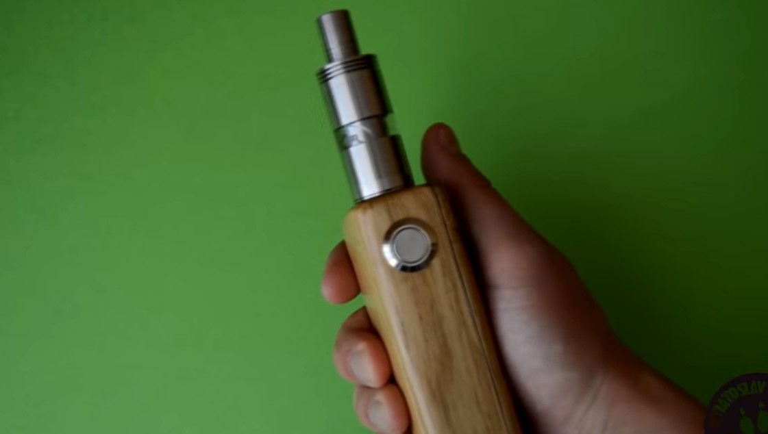
Previously, the author has already created vapes from aluminum and wood. In this project, he decided to create a vape made of plastic.
The decision to print the case of the product using a 3d printer is very logical.
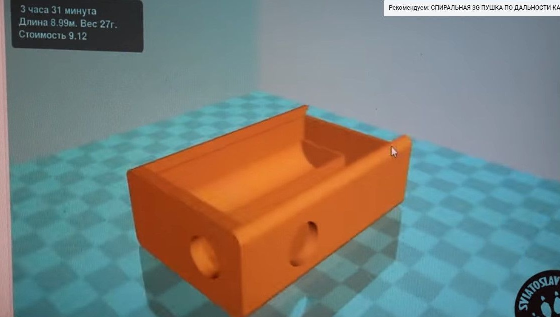
For in the modern world, printing various plastic products using 3D printers is very cheap and affordable.
Actually 3D printers are no longer something exclusive and unusual. Now printing is available to the general public, which is friends with modeling programs.
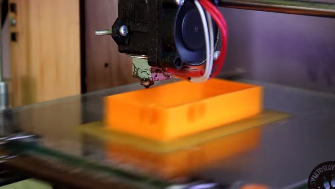
A friend of the author recently got a 3d printer, and helped print the case for vape.
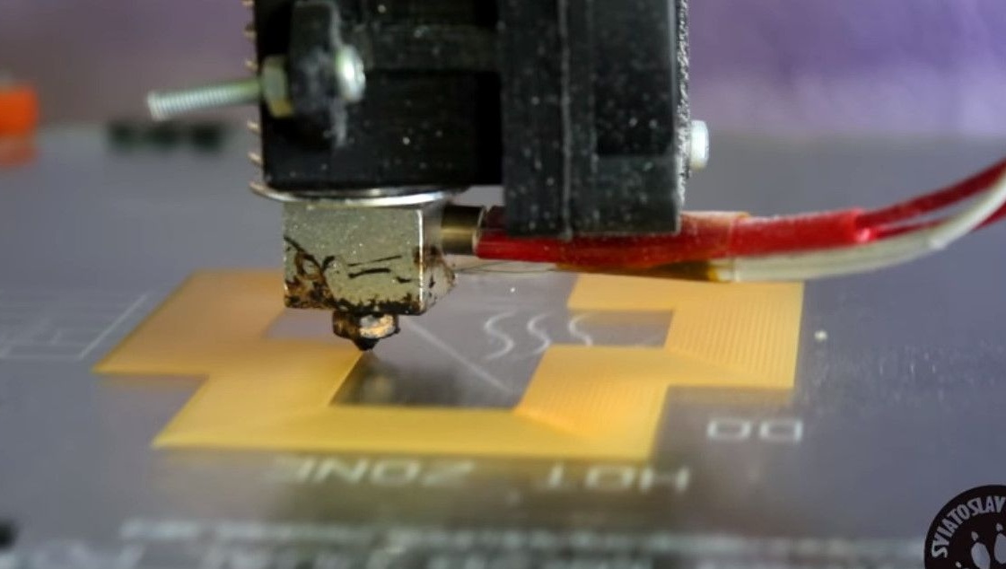
When ordering a similar case in a company engaged in 3D printing, its cost can be about $ 5.
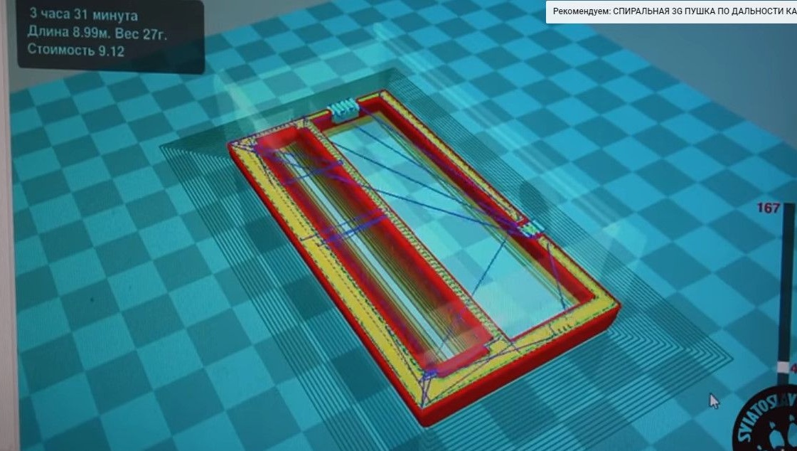
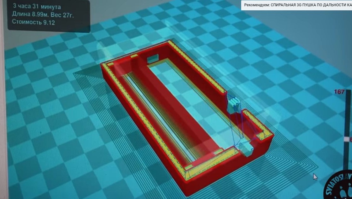
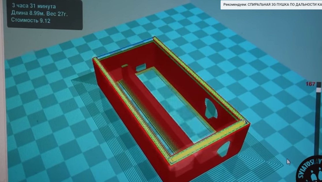
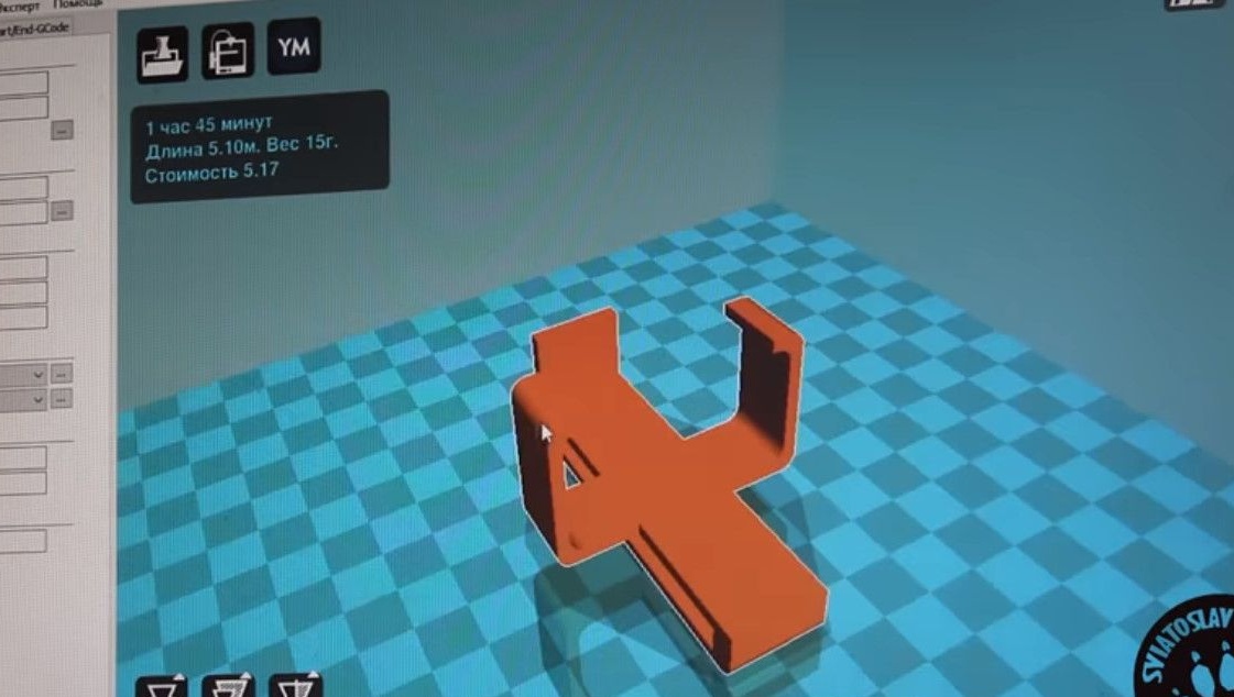
For printing of this particular design, links to model located under the original video in the description.
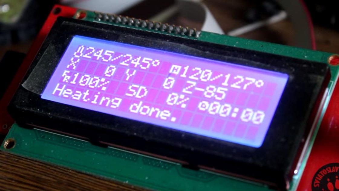
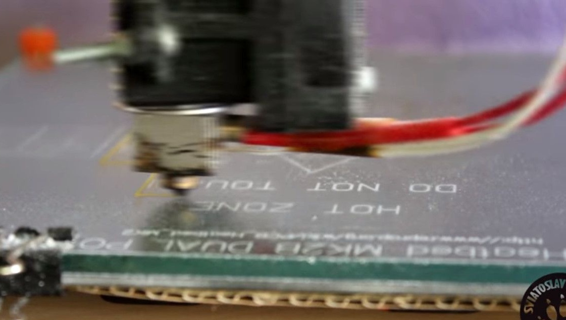
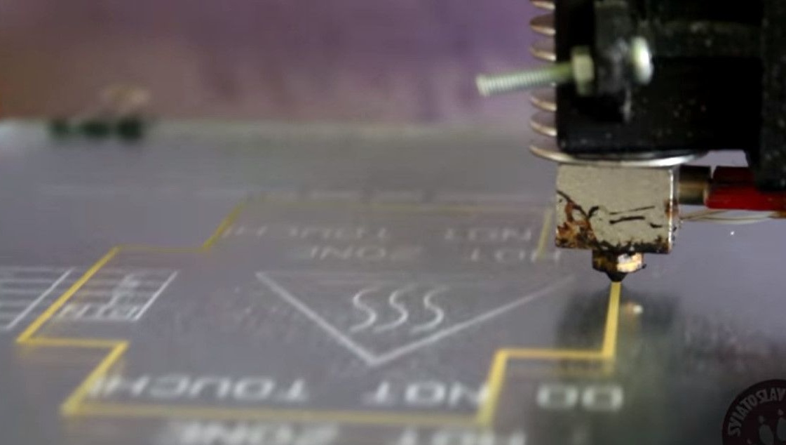
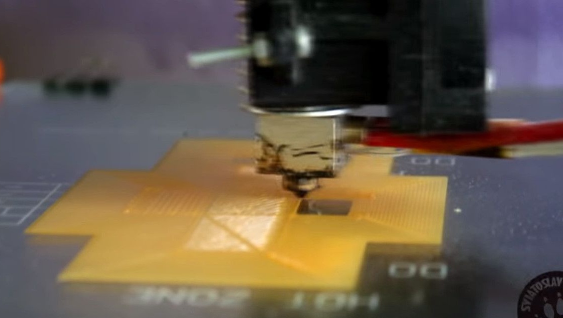
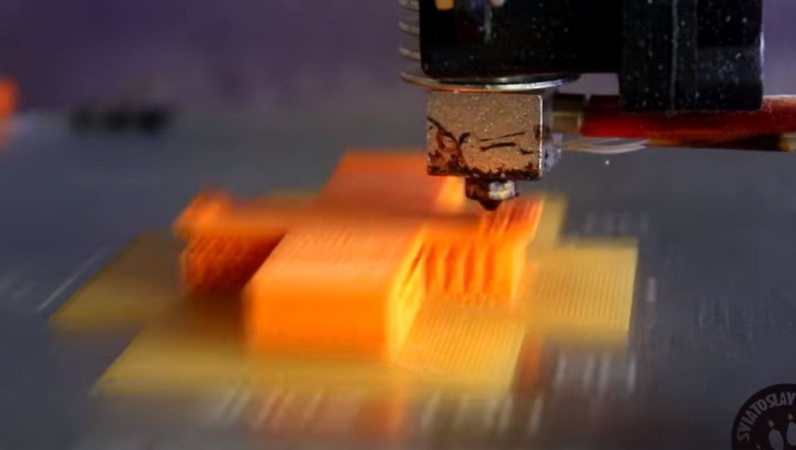
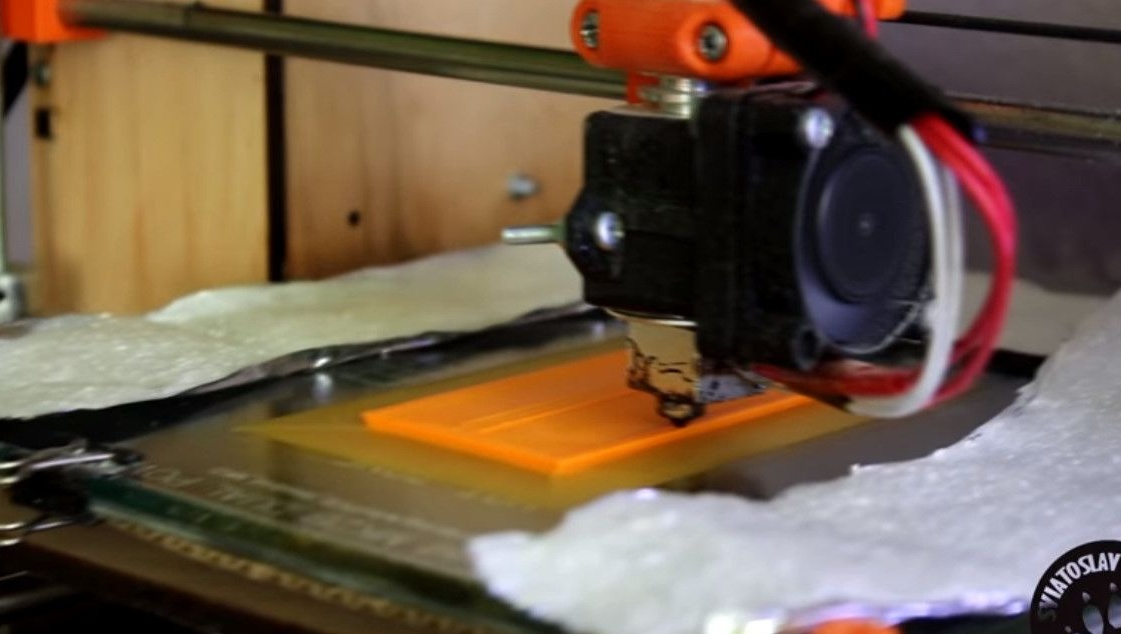
Printing itself takes several hours.
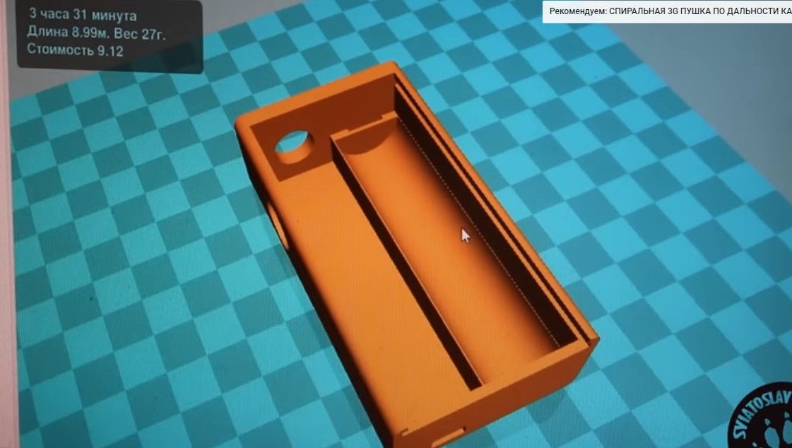
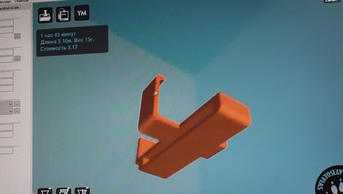
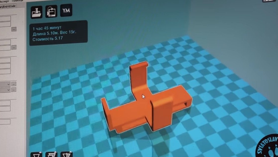
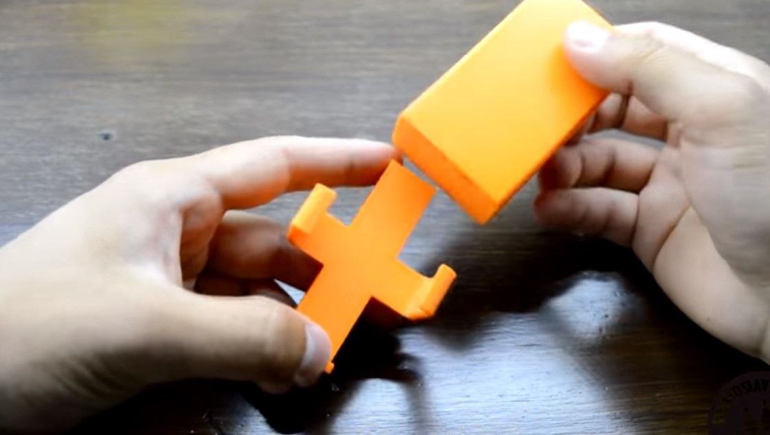
At the same time, the author prints the belt mount for the vape itself.
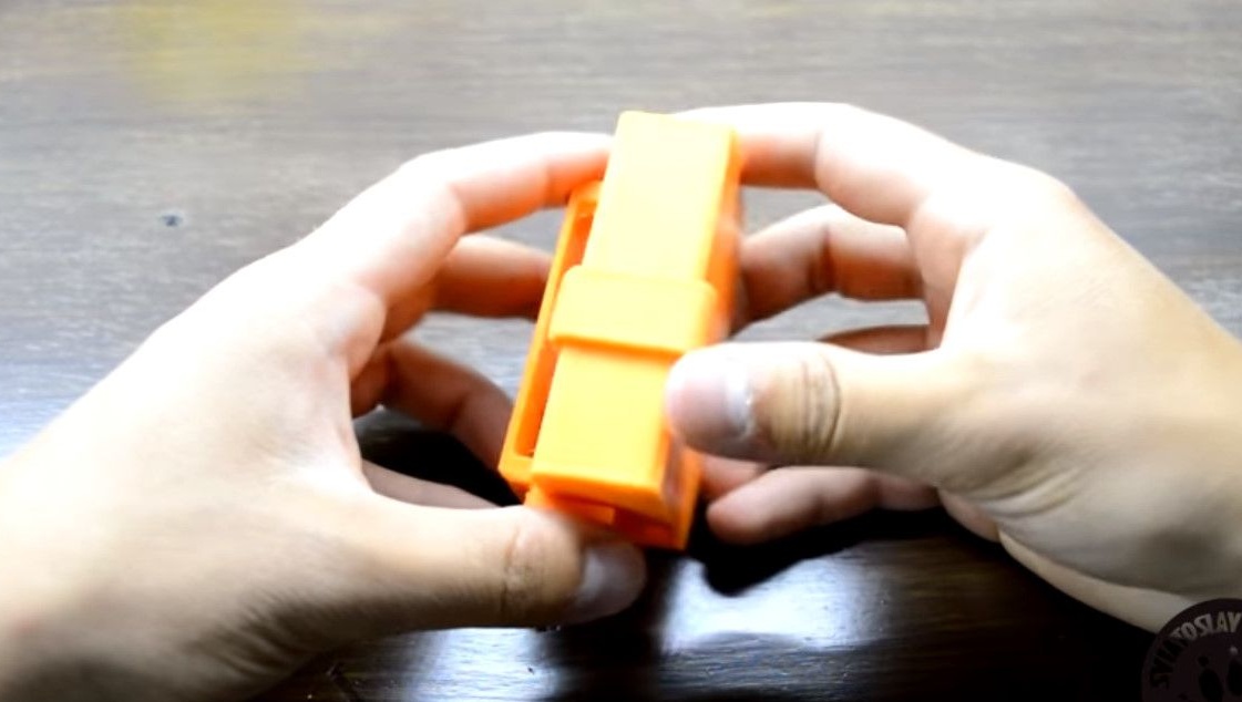
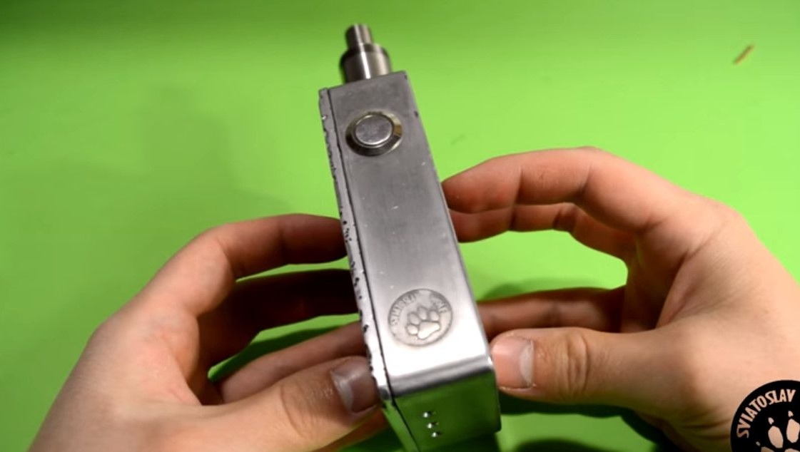
Excellent plastic density, very good.
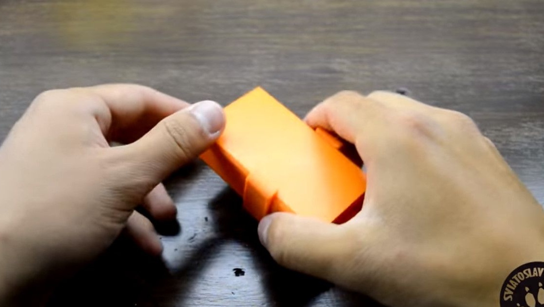
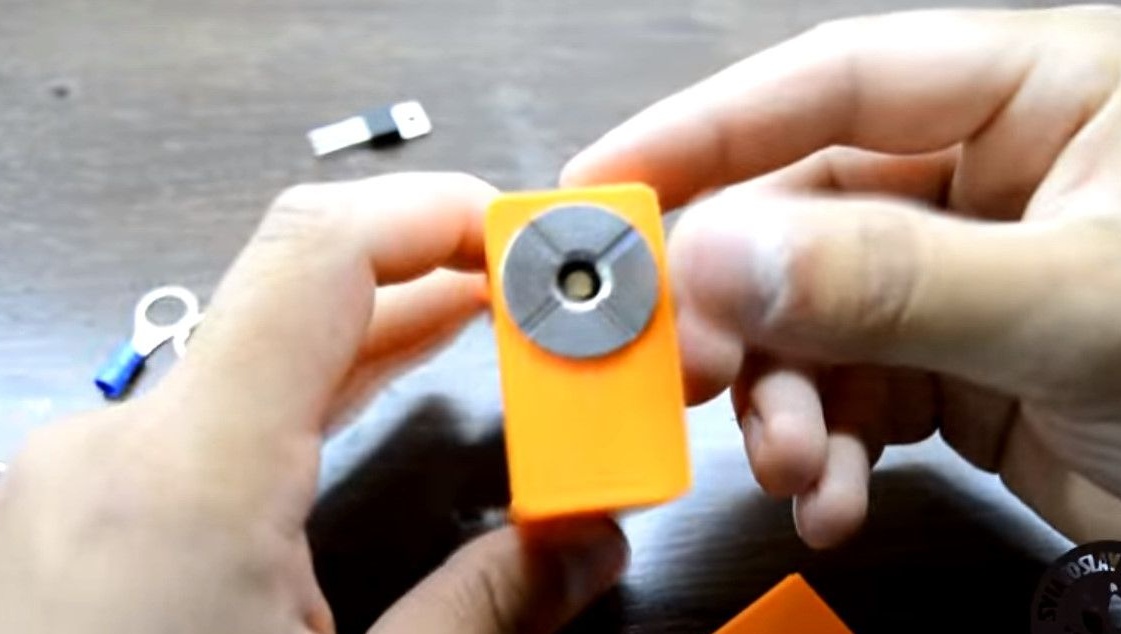
The mount also sits well, you can start assembling.
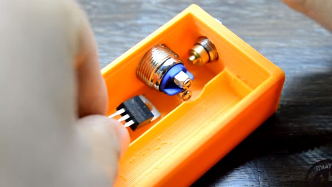
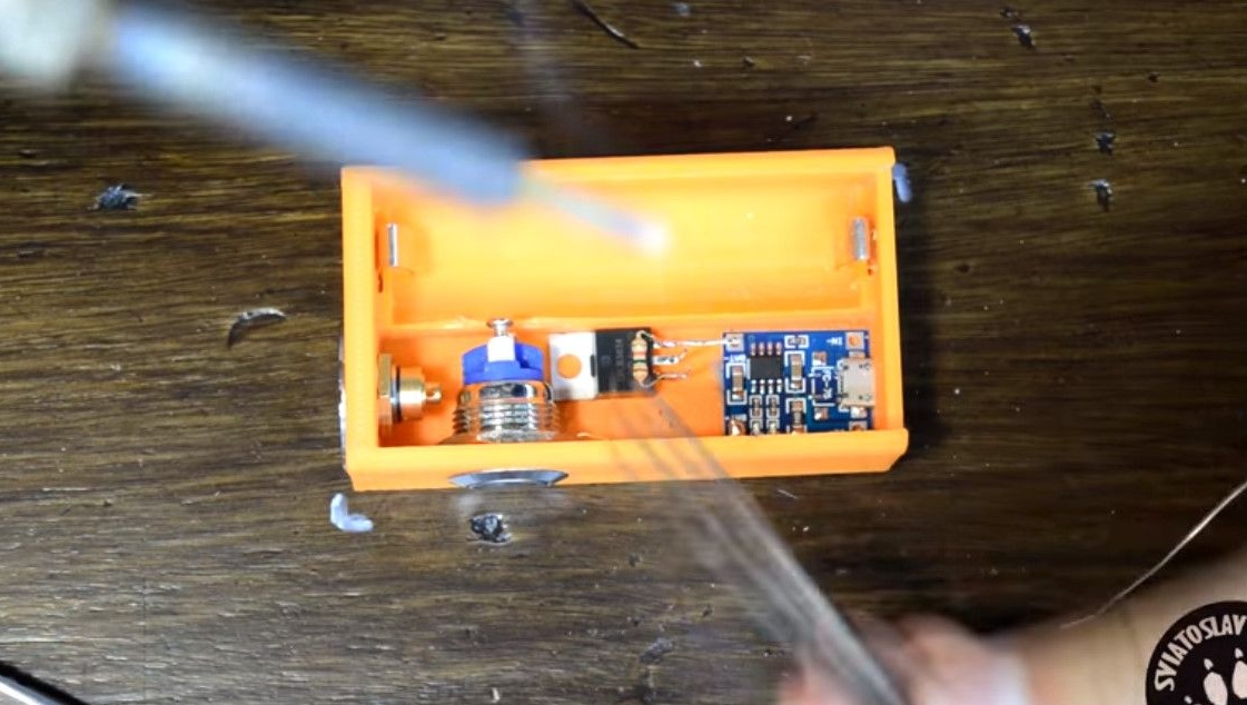
Except boxing we will need
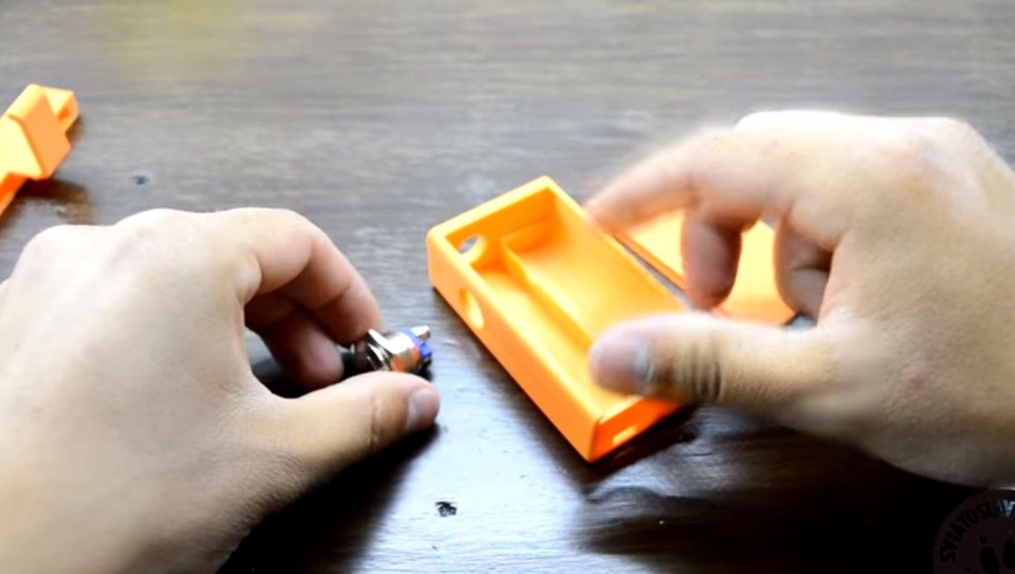
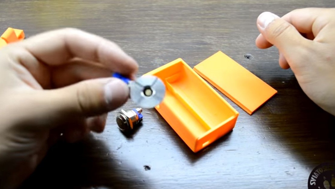
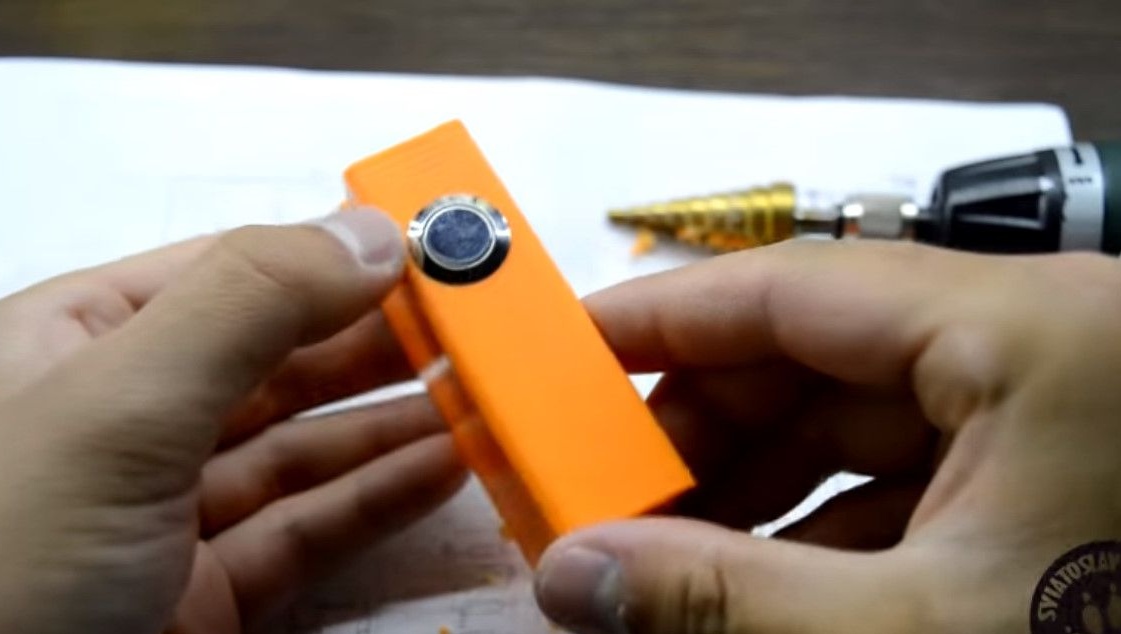
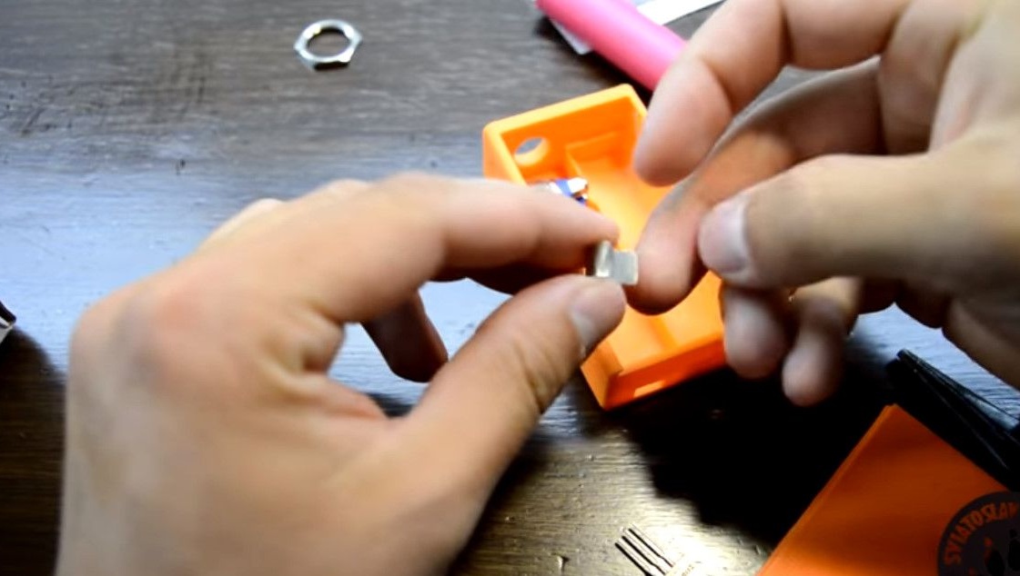
1. The button is anti-vandal metal. Still, temperatures and currents can be high.
2.510th connector.
3. Resistor with a resistance of 15 Kilohms.
4. Board for charging the TP4056 battery.
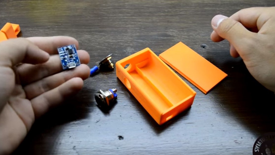
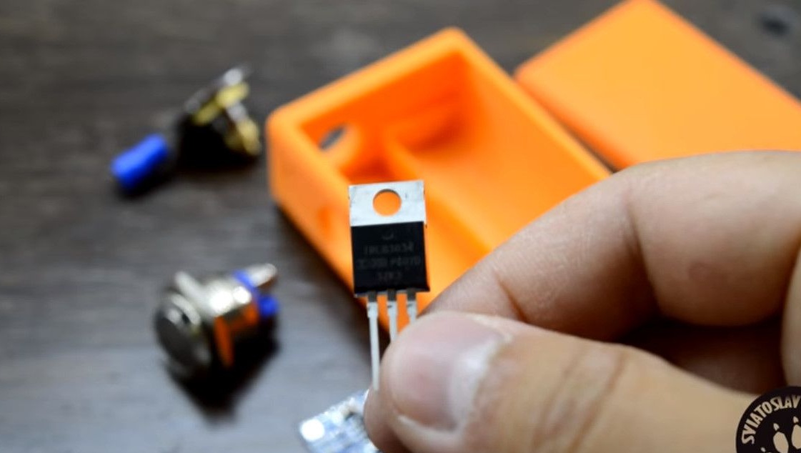
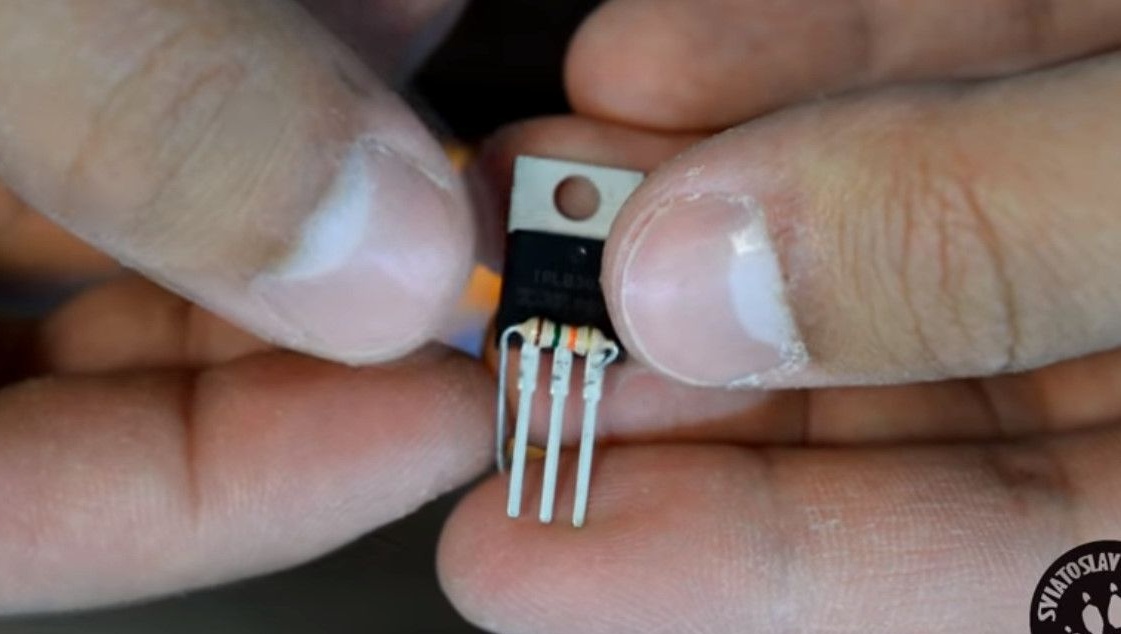
5. Transistor MOSFEET IRNB3034.
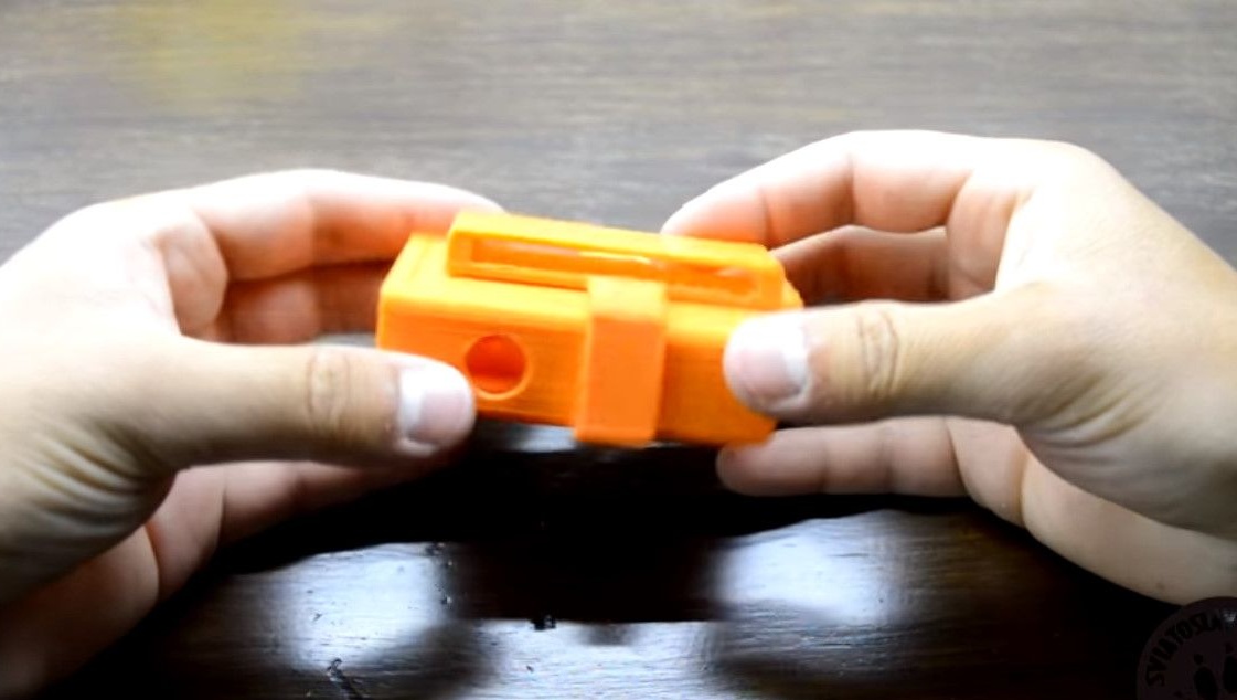
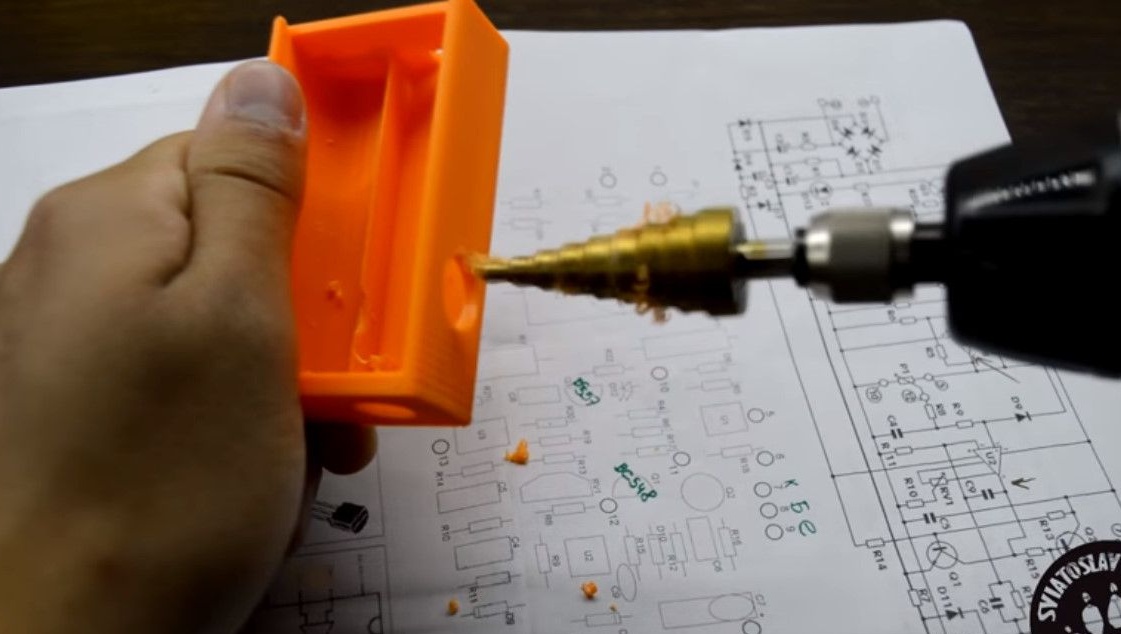
In the program, the button hole was indicated a little incorrectly.
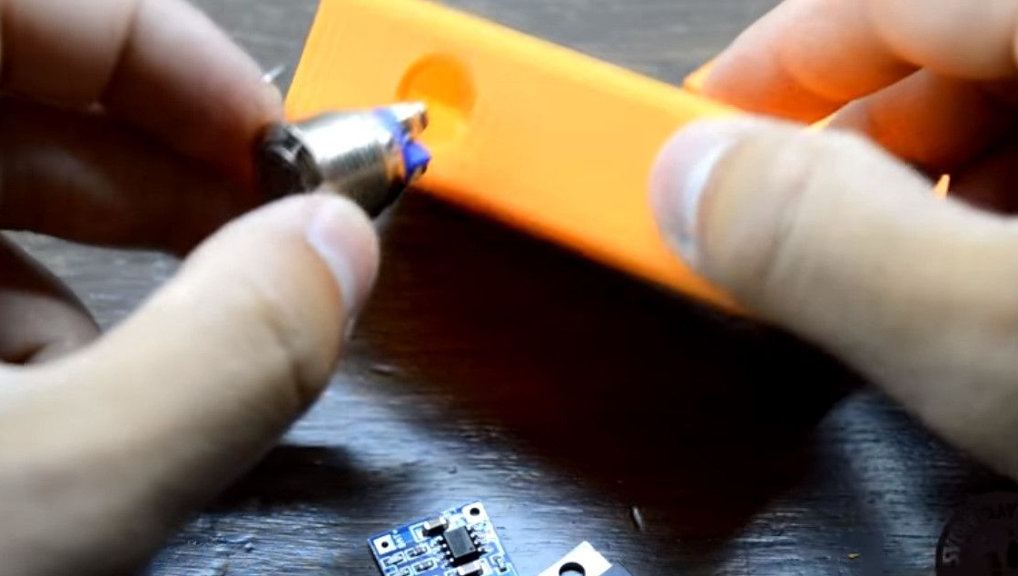
Will have to drill it.
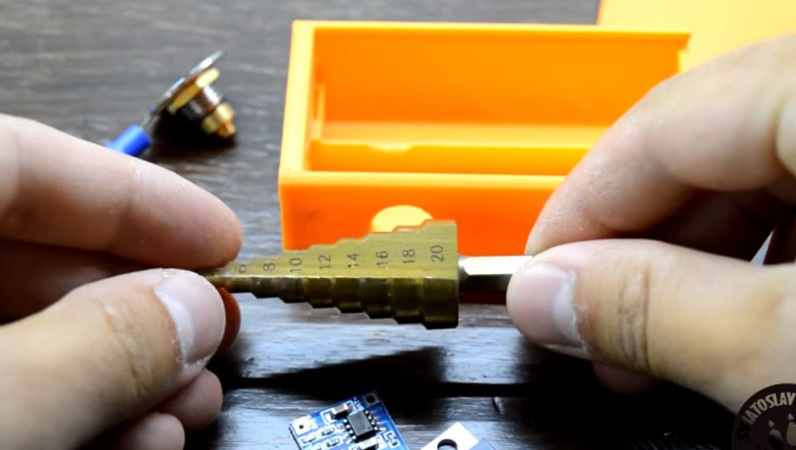
The easiest way to drill a hole is with a step drill.
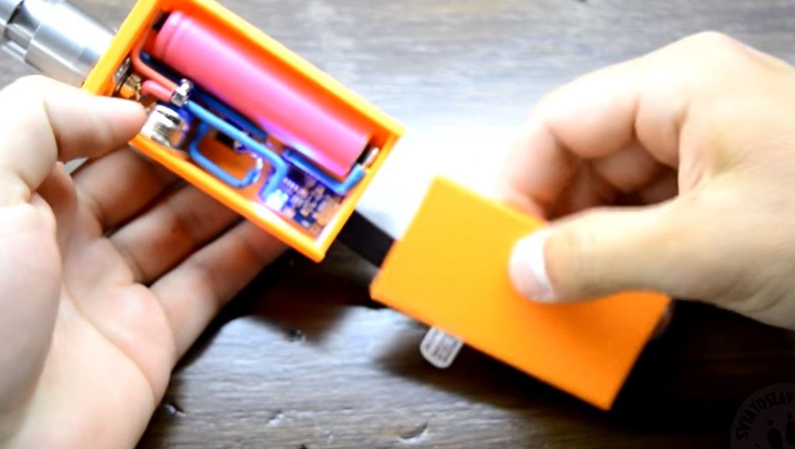
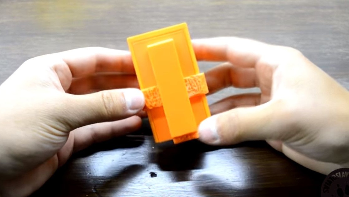
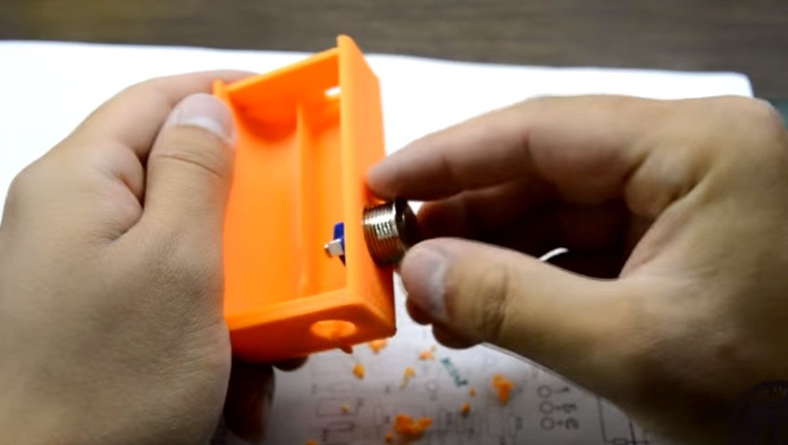
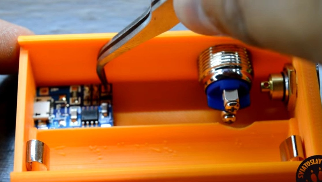
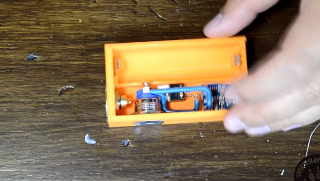
After mounting the button, you need to attach all the other details to be sure of the correct size of the manufactured box.

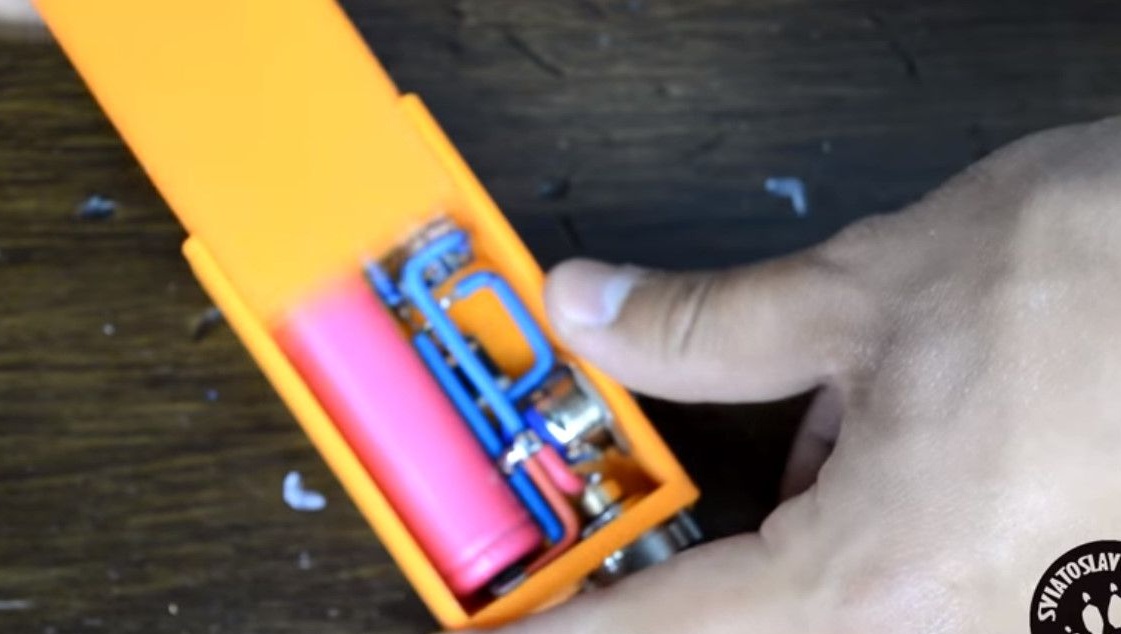
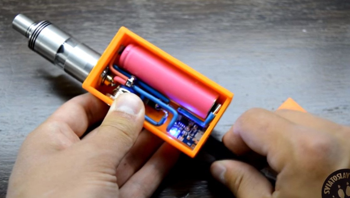
Further. We make metal terminals for clamping the battery.
This is easiest to do with wide nickel strips, they can be taken from dead batteries from a screwdriver or laptop.
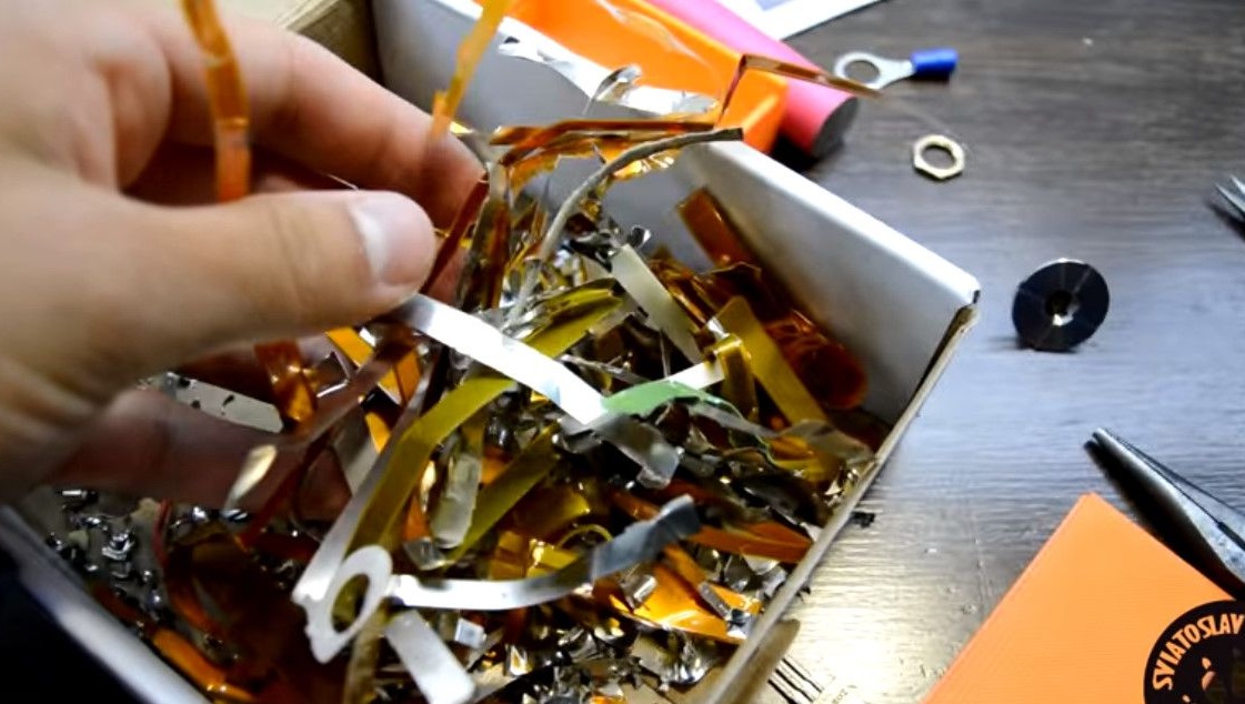
From them, the author cuts out parts that fit the size of the printed fixtures for them.
These are the plates that should work.
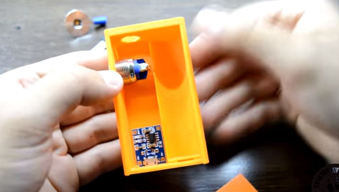
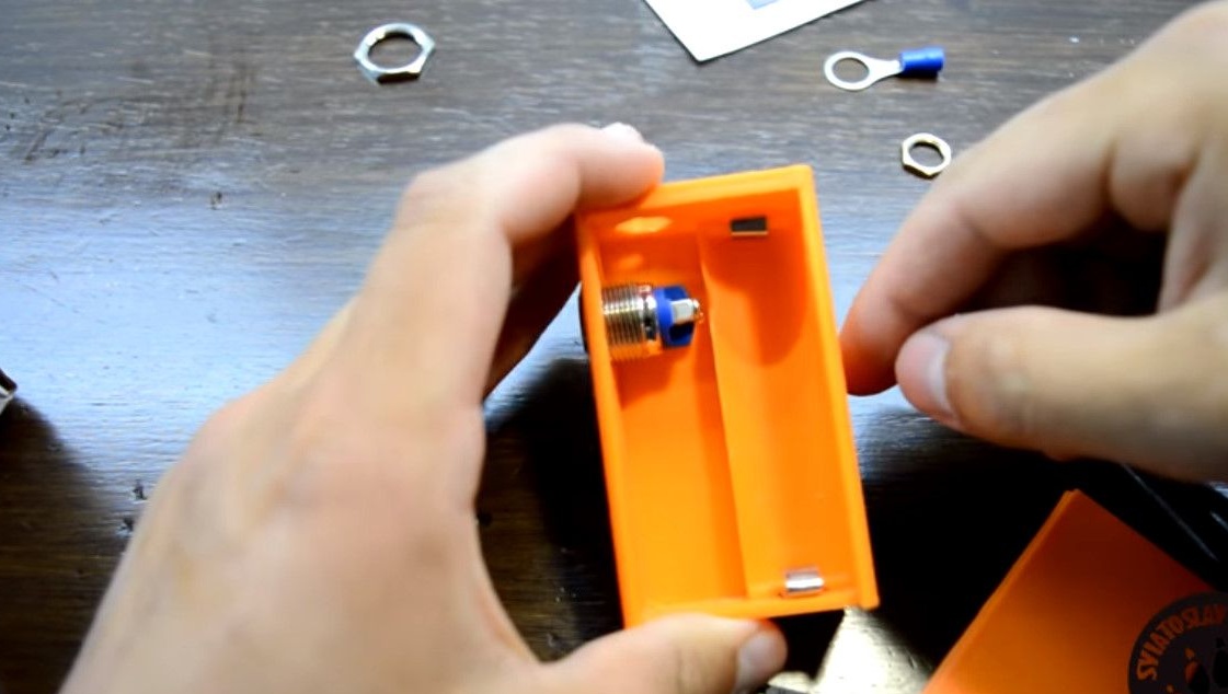
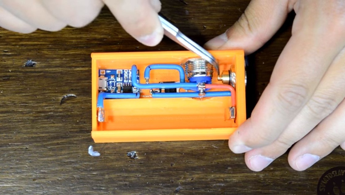
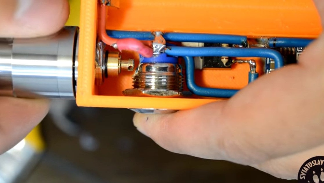
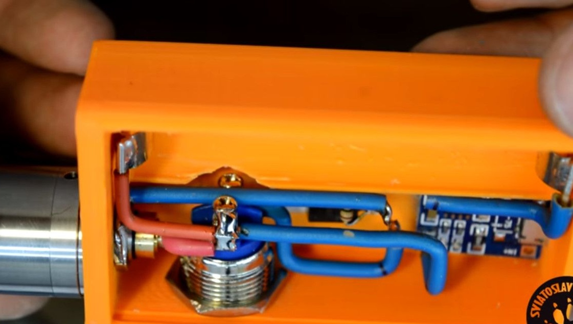
We fix the 510th connector, it is important to tighten the fastening nut.
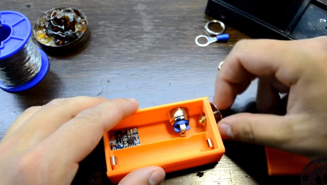
So that when installing the dismantling of the atomizer, he did not unwind.
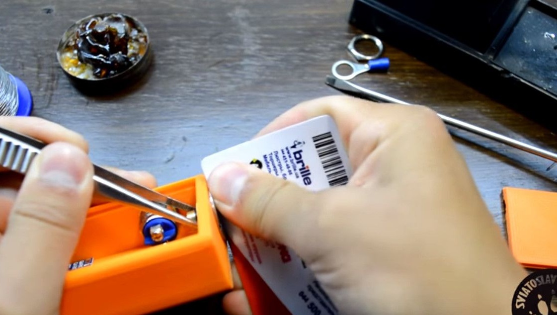
We fix the battery charge control board to Poxipol epoxy. It is possible on superglue, hot-melt adhesive is not welcome, because it can melt from temperature. Just the connection should be tough.
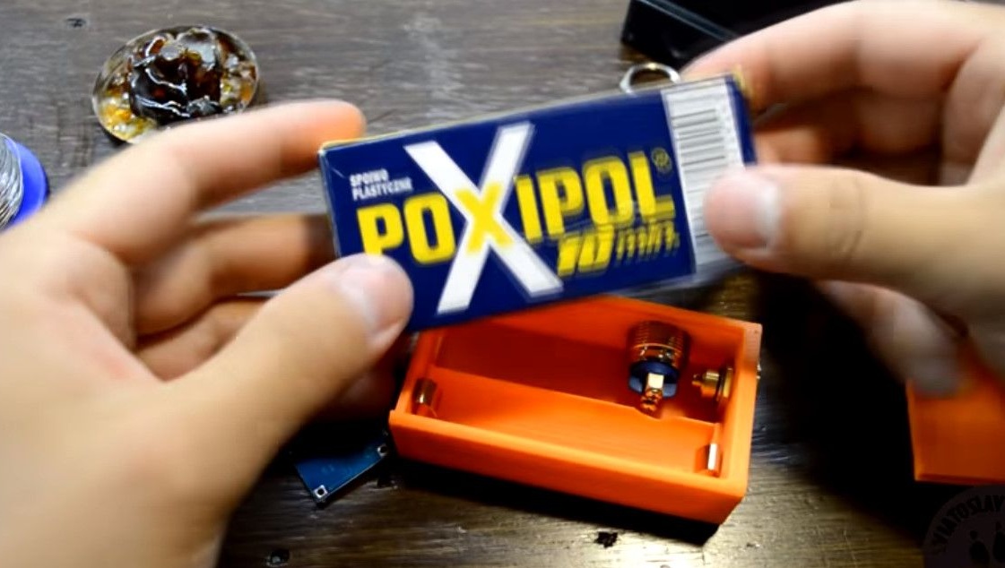
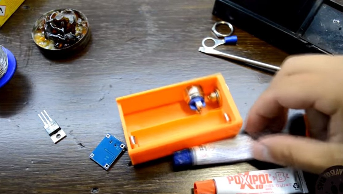
We mix both components of the glue one to one.
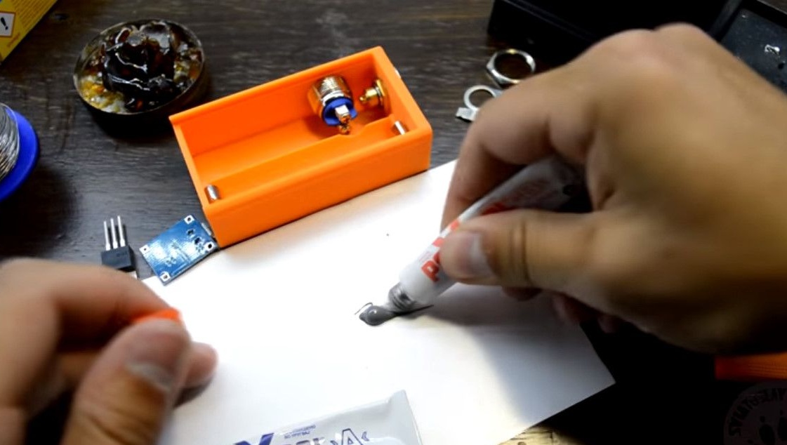
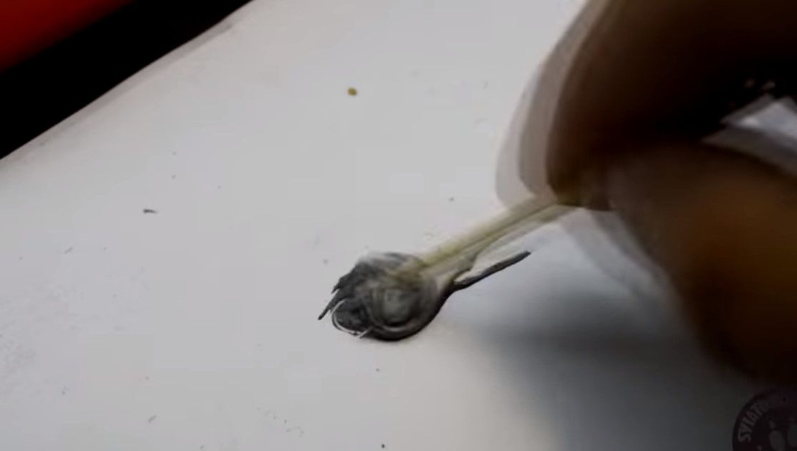
This particular adhesive has very good adhesion.
It is advisable to strip and degrease the board.
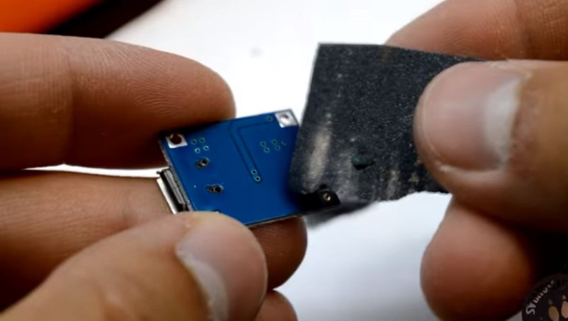
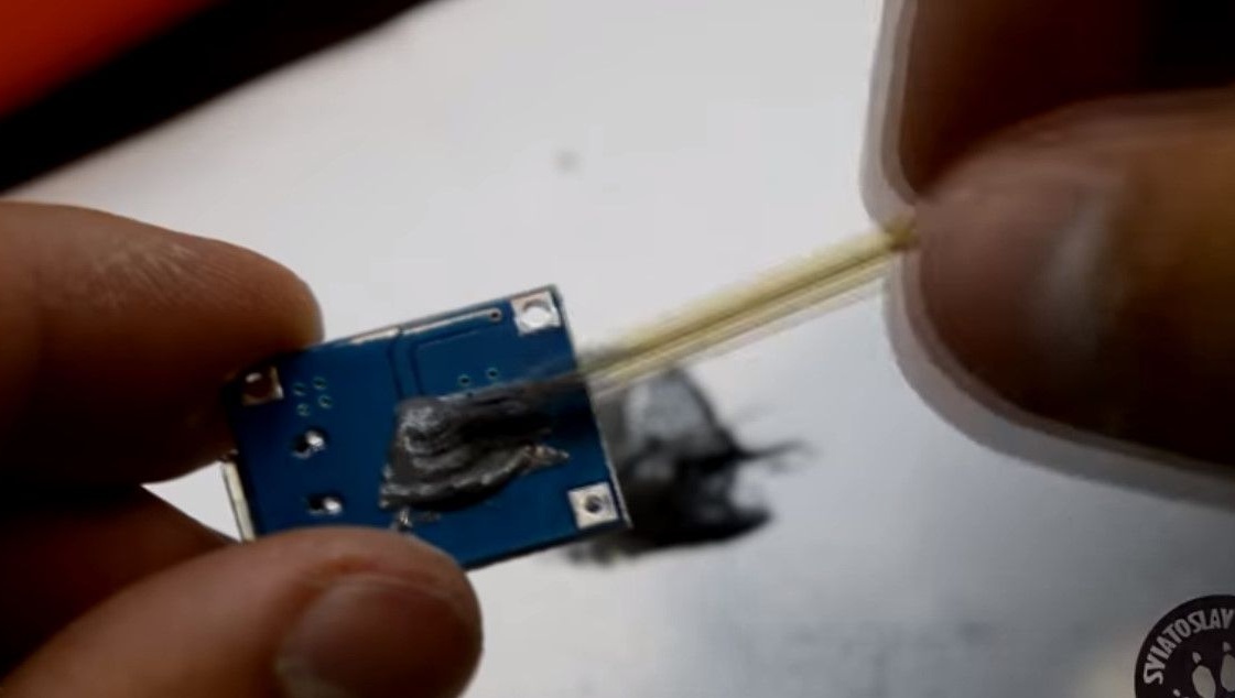
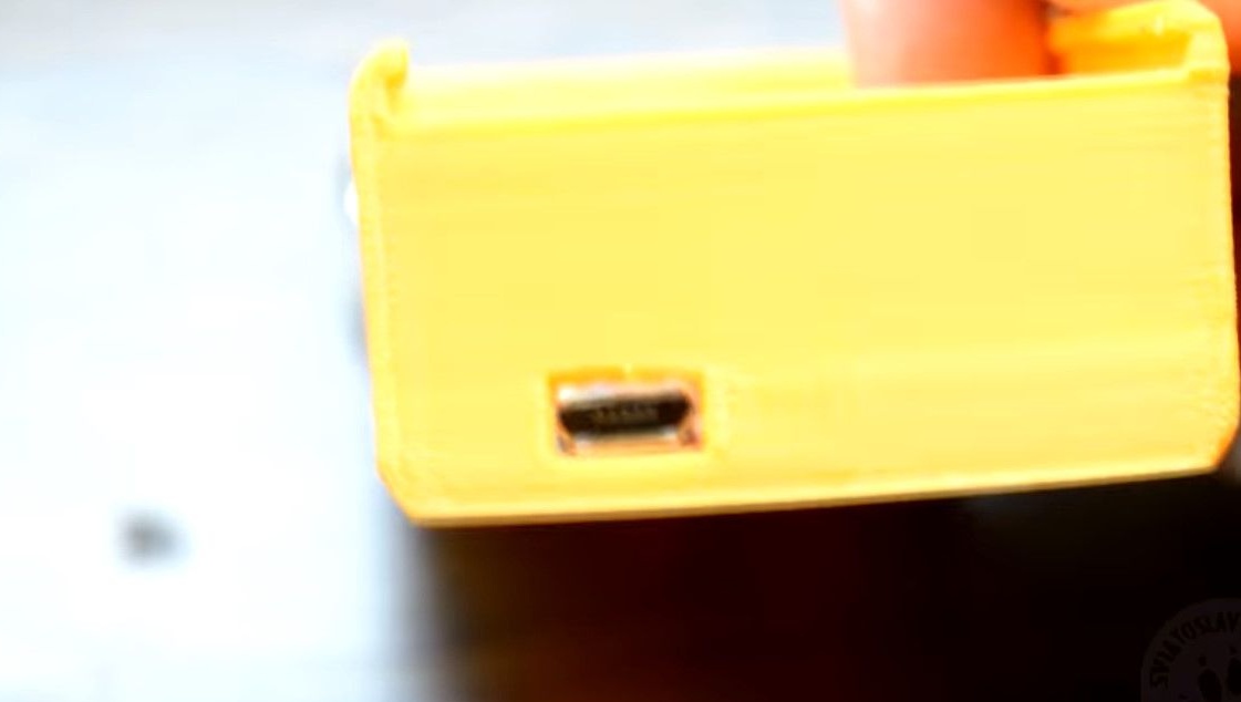
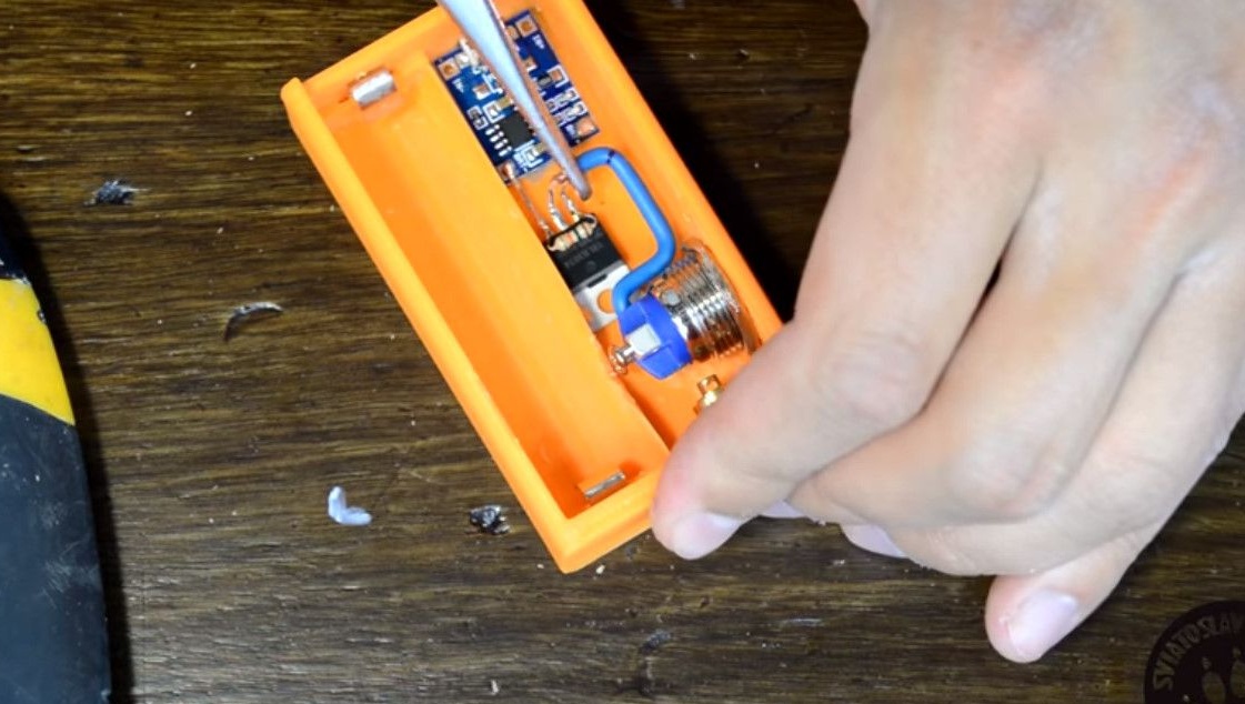
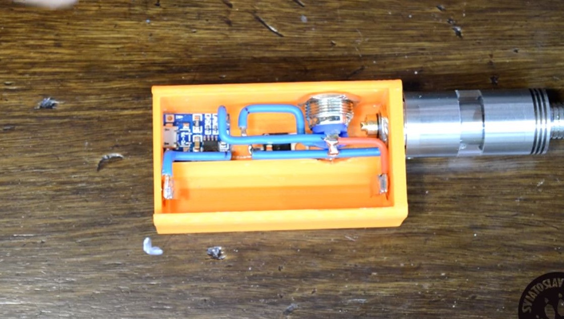
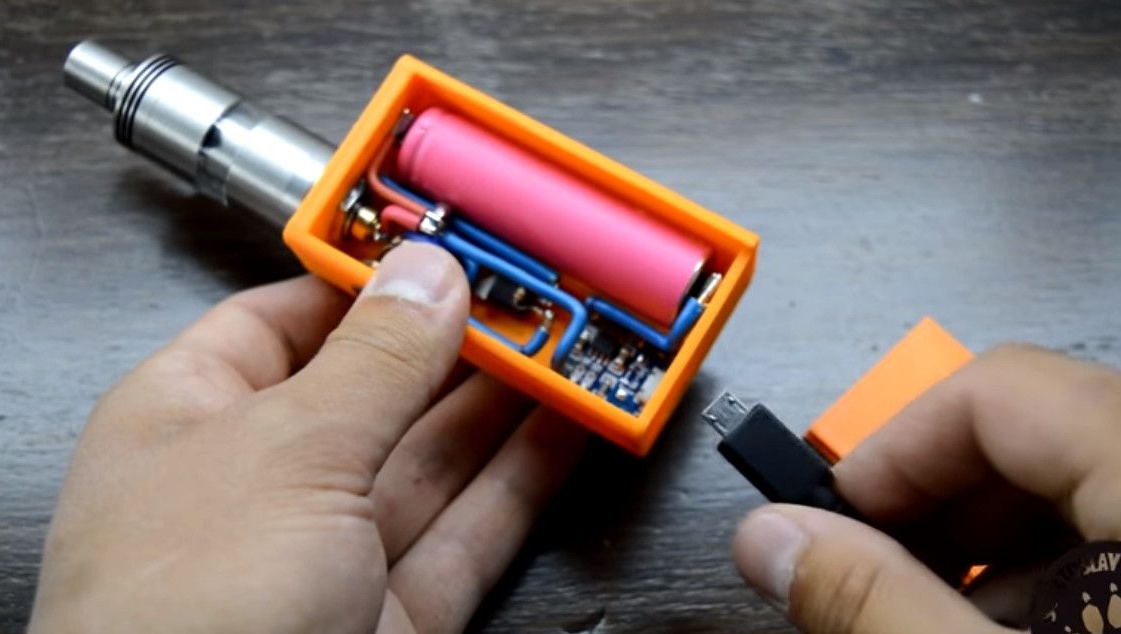
We install the charge controller in the case so that the MicroUSB connector gets into the hole for it.
In just ten minutes, the glue will harden, and the board will not come off just like that.
The next step is to install the MOSFET.
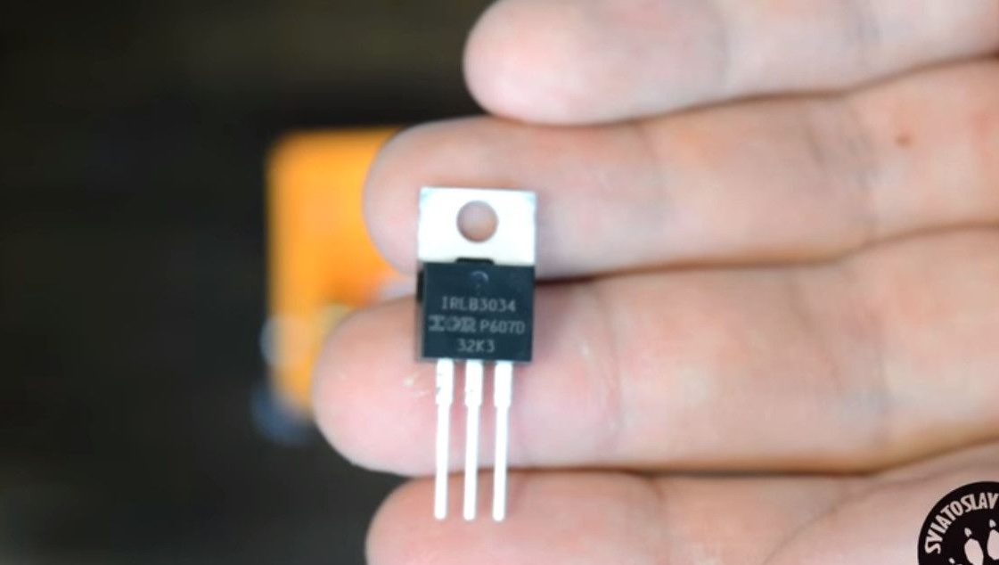
At this stage, we install the mosfet transistor IRLB3034, it performs the function of a power relay.
Simply put, it turns on the power of the power spiral of an incandescent atomizer.
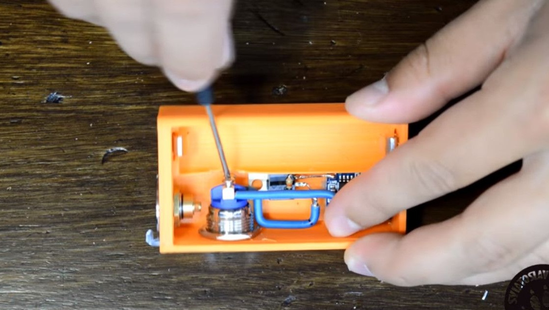
We solder a resistor of 15Kom to the terminals of the transistor.
The rightmost terminal of this transistor is soldered to the negative terminal of the battery charging controller.
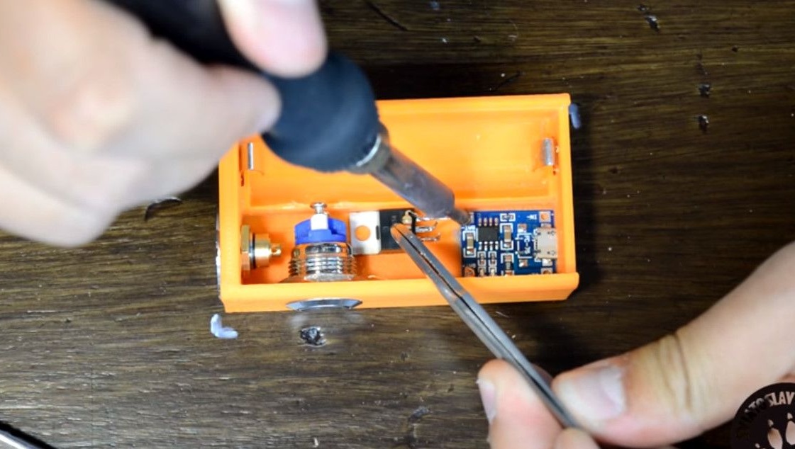
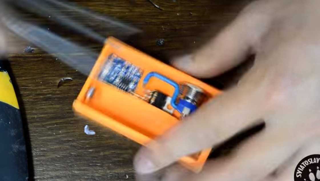
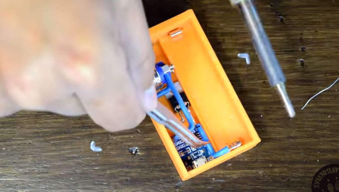
Now we make beautiful connections from power, thick wires. The thickness of the veins is at least two millimeters.
Before the final fixing of the wires by soldering, we beautifully bend the wire.
So that he does not walk when replacing the battery or disassembling the device.
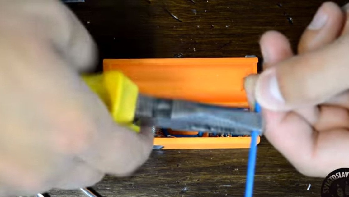
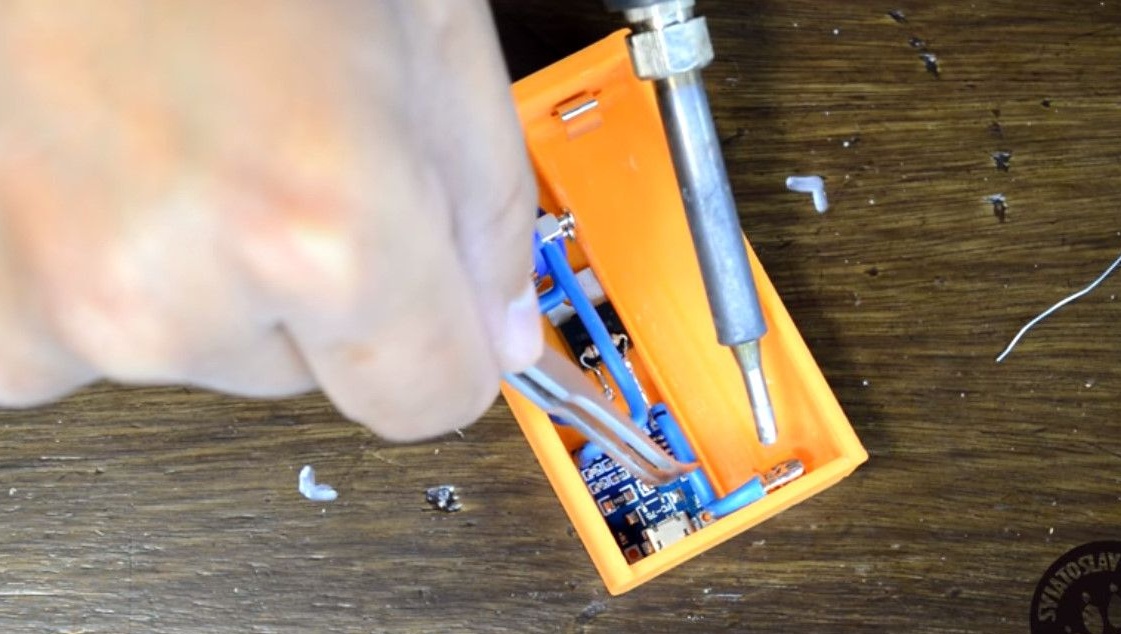
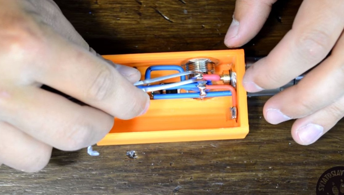
One edge of the wire will be soldered to the leftmost contact of the transistor, and the second to one of the button pins.
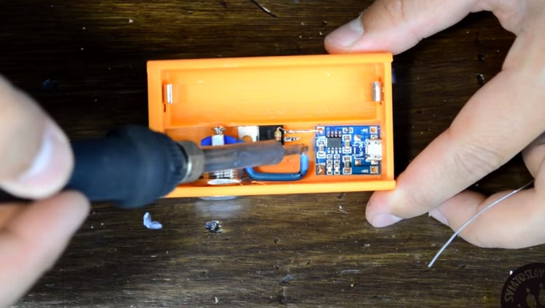
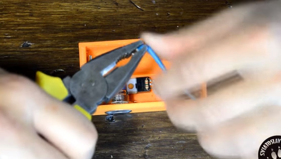
Beautifully bend another segment from a copper conductor.
We connect the buttons to the second contact.
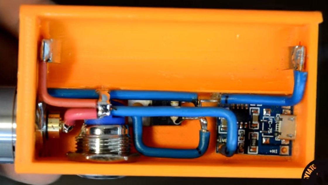
We connect and solder to the positive contact of the charging board.
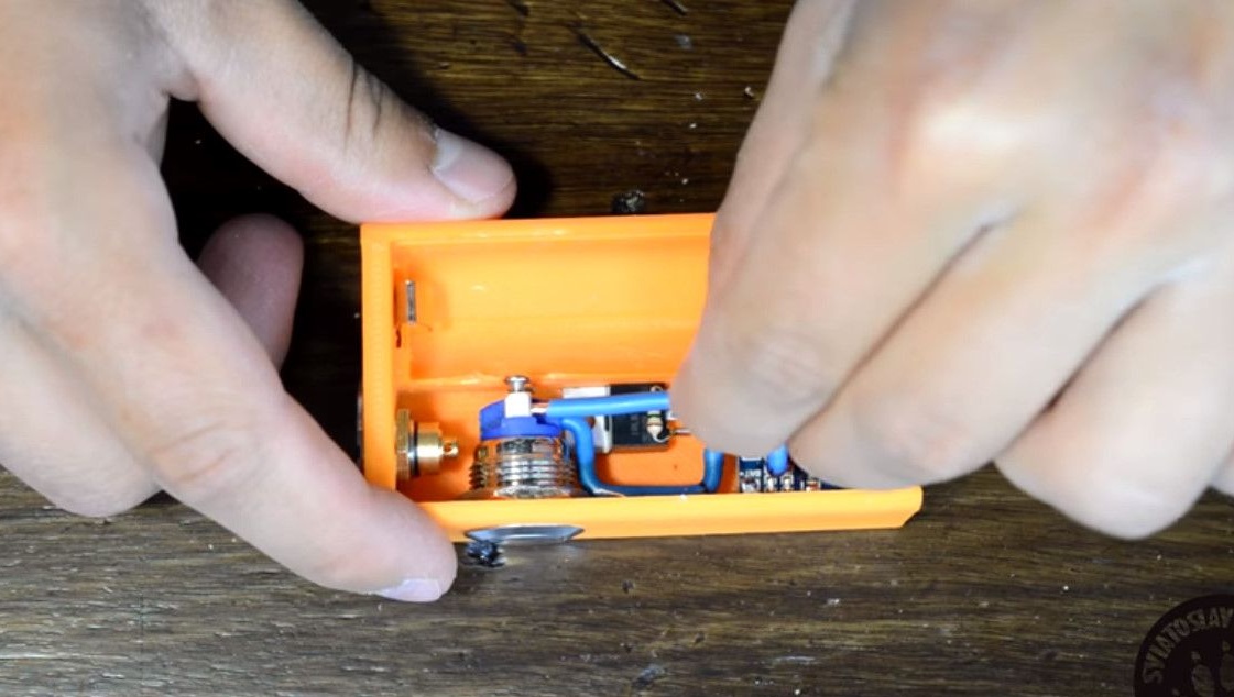
Negative contact plate for connecting the battery - connect with the negative terminal of the battery of the charge controller.
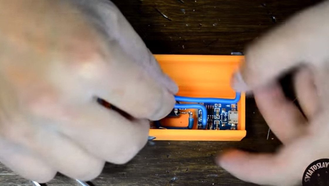
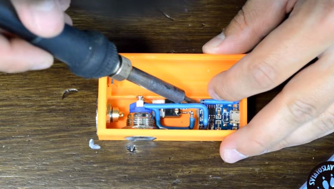
The mass of the 510th connector must be connected to the middle output of the transistor.
We connect the positive terminal of the battery to the plus of the charging board.
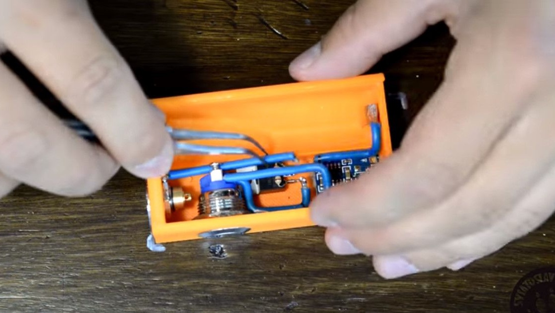
And to the remaining pin output.
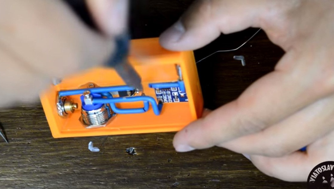
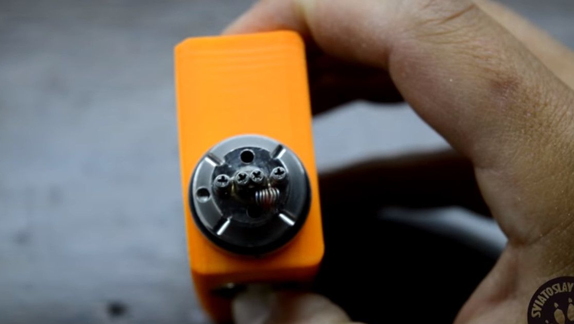
It remains to solder to the plus of the 510th connector a small piece of stranded copper cable.
A stranded wire is required so that the 510th connector in the central terminal has a slight backlash.
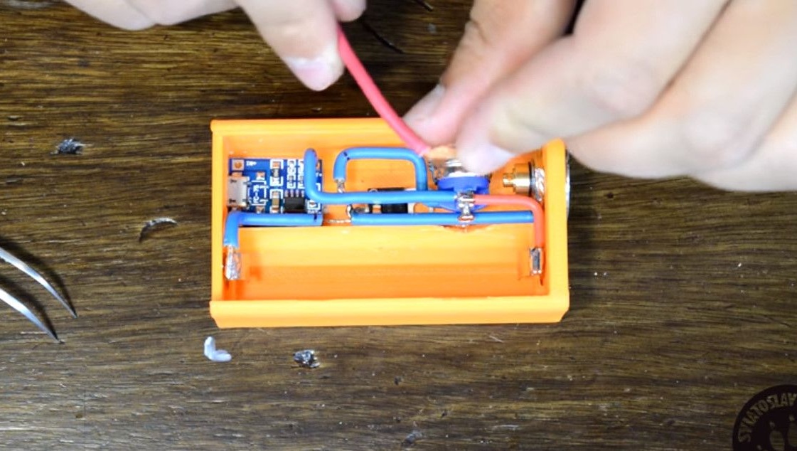
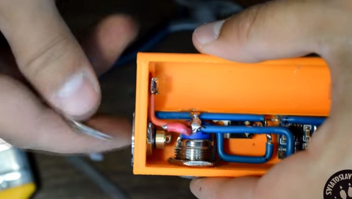
Backlash is necessary for good contact under various atomizers.
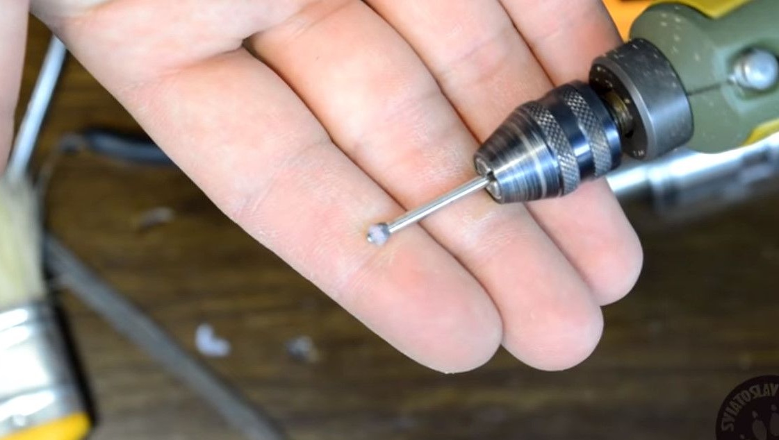
For greater reliability, you can slightly file the terminal, and thereby increase the stroke of the central terminal.
It’s easier to do this with a drill.
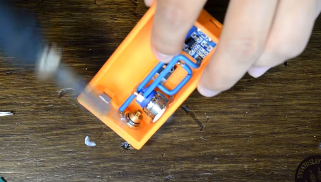
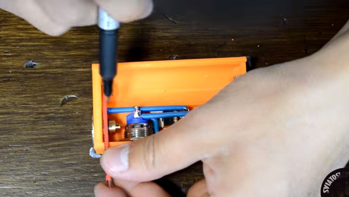
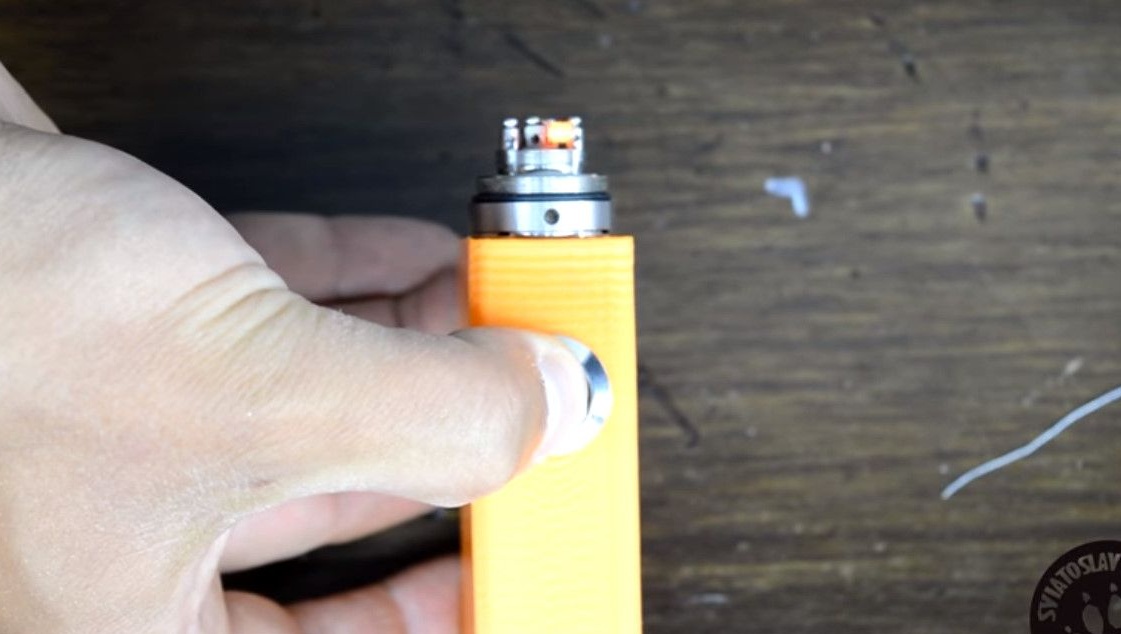
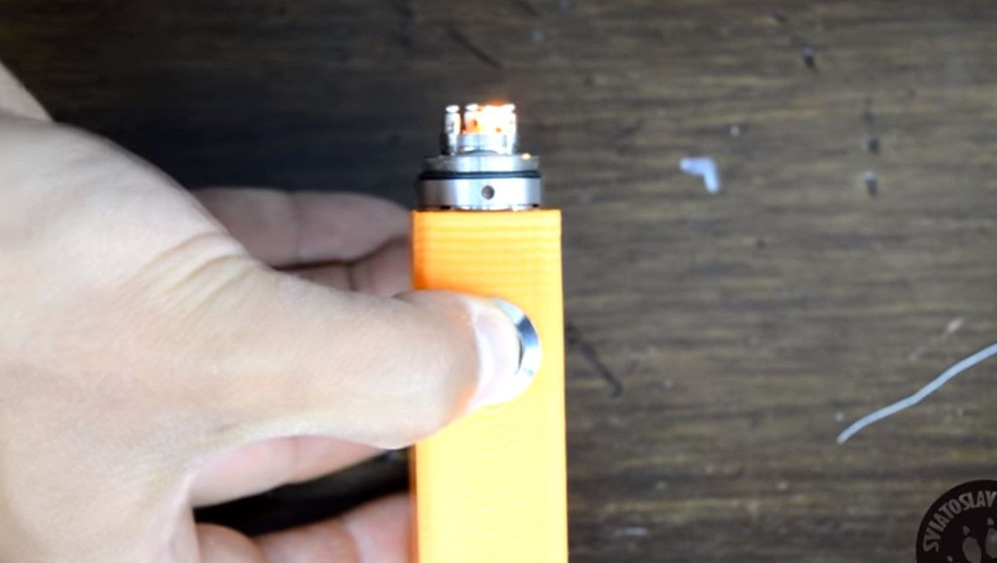
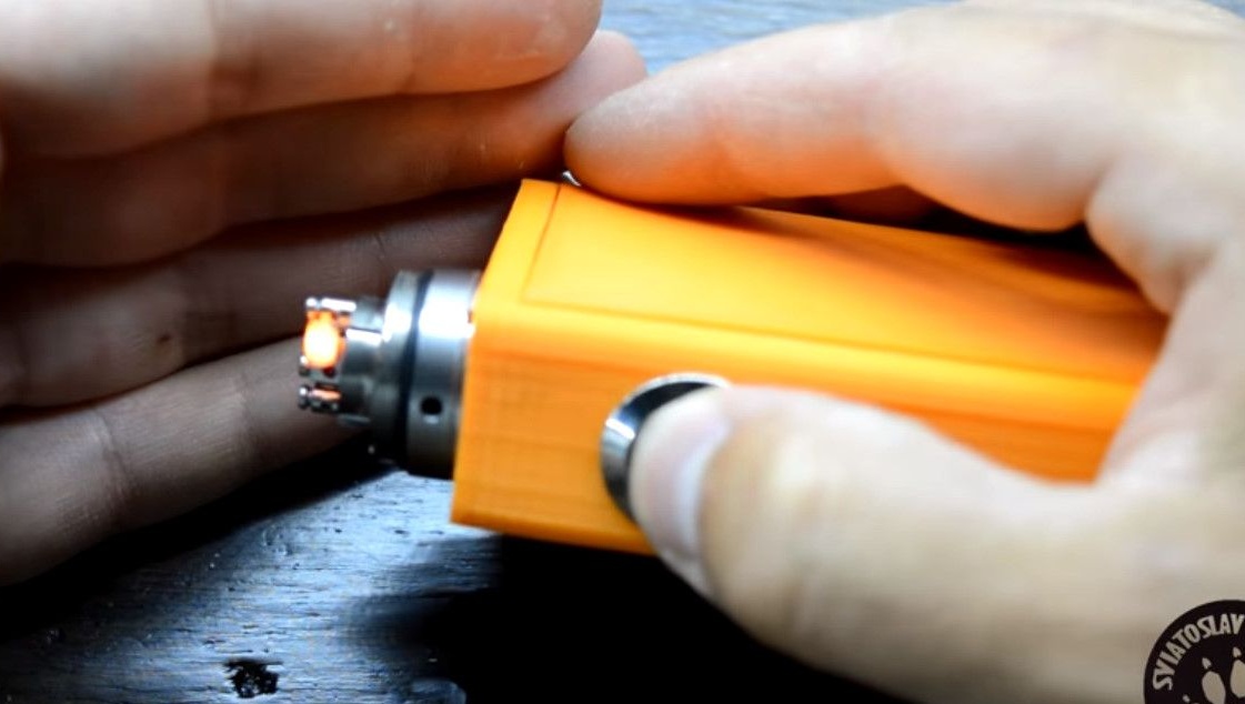
Install the atomizer. And solder the terminal.
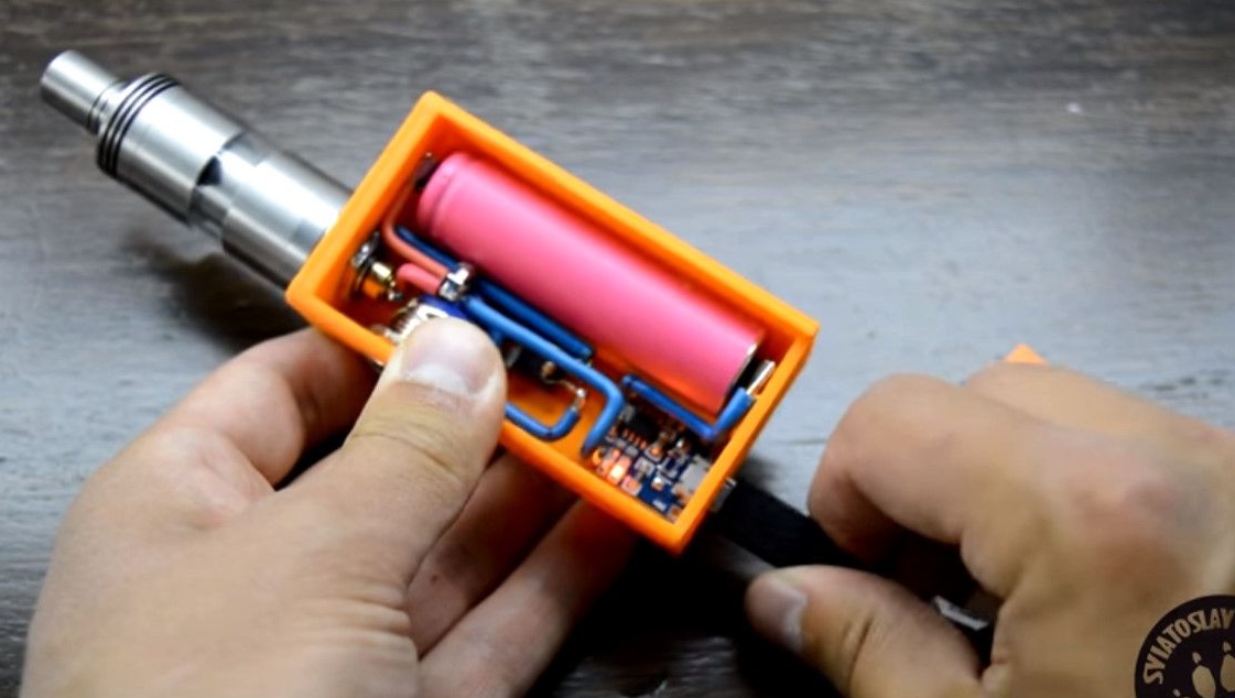
Now the battery.
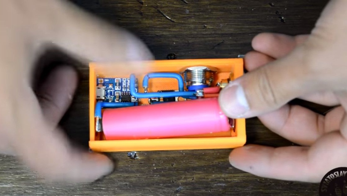
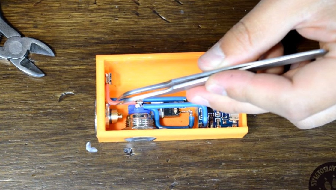
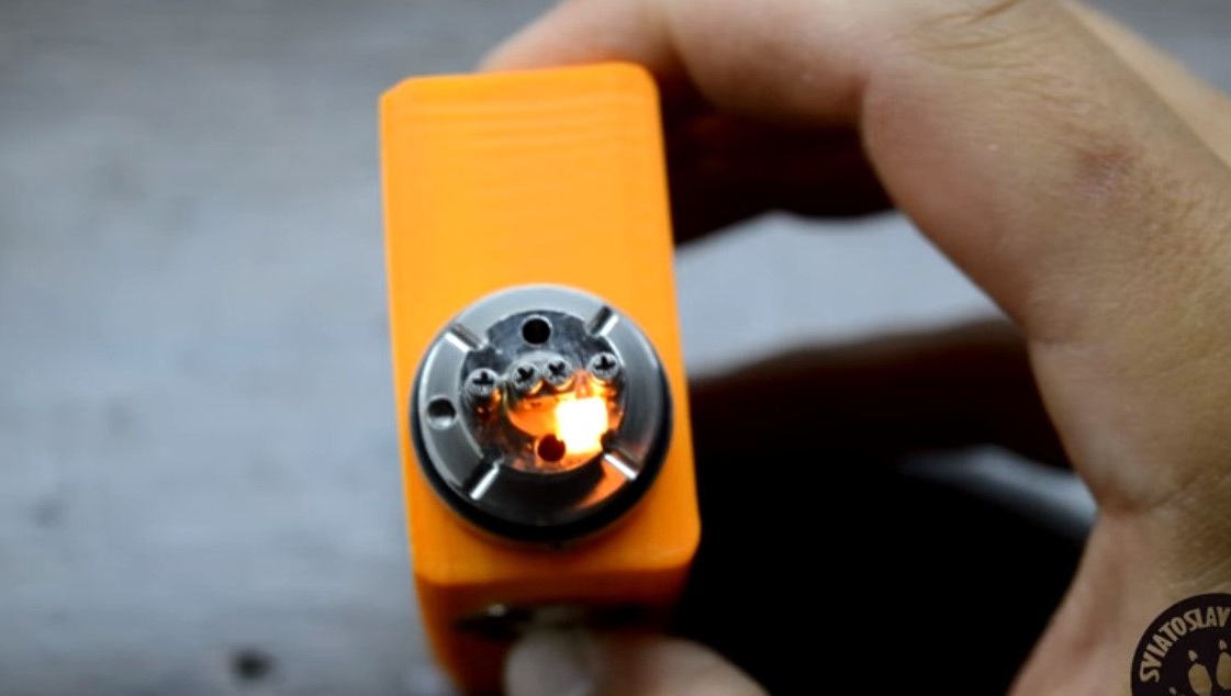
Check the circuit in operation. The spiral smokes and glows, and therefore all connections are made correctly.
It remains to verify the operation of the charging controller.
A blue LED indicates a fully charged battery.
If the red light is on, then the battery is in the process of charging.
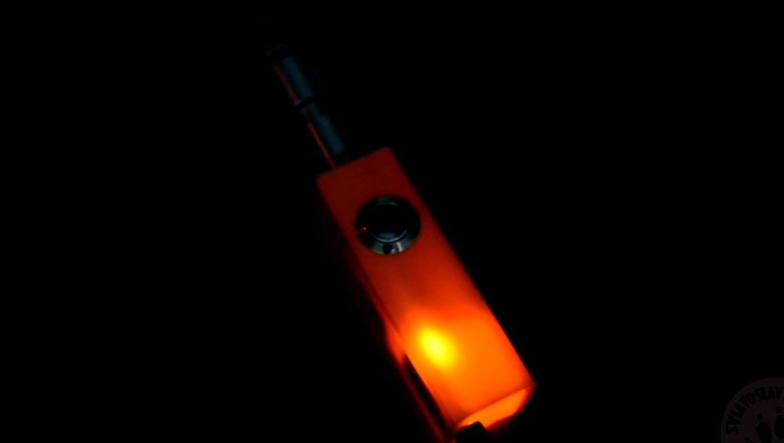
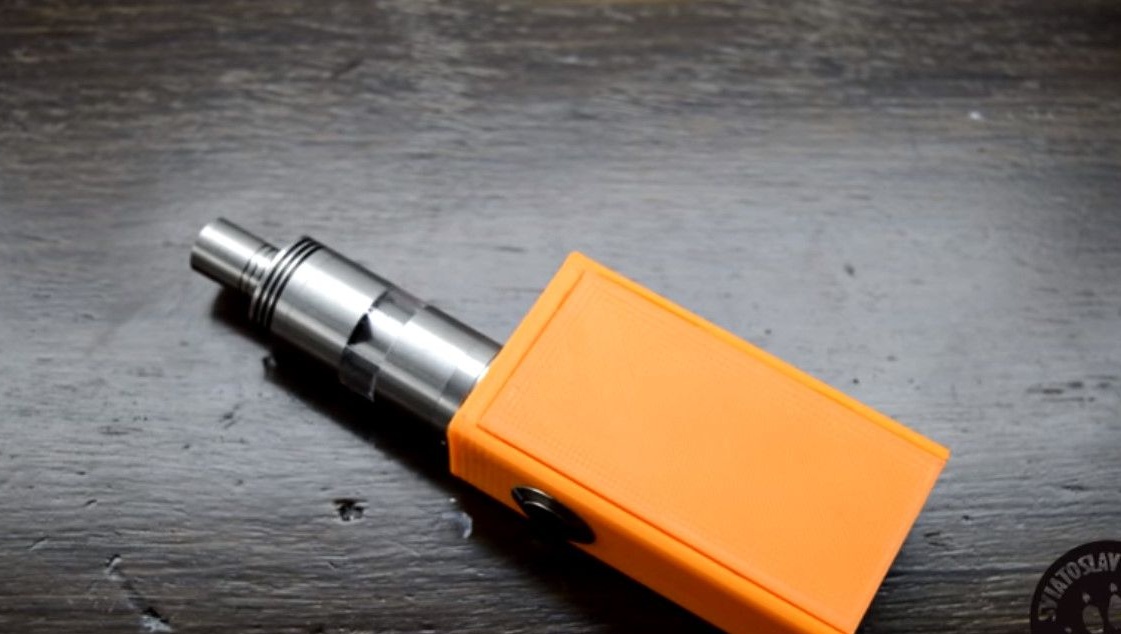
Actually the finished device looks good in the dark, and the glow of LEDs breaks through the case.
Homemade prepared for you by SVIATOSLAV WOLF.
A link to the original video is located under the text of the article. Source Button
Good luck to everyone with homemade! And good ideas.