
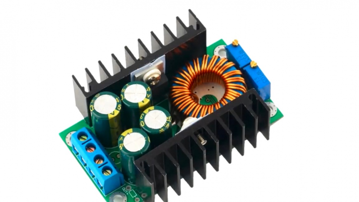
Continuing the topic of power supplies, Roman (author of the YouTube channel “Open Frime TV”) presents such a compact unit on the popular LM2576 chip.
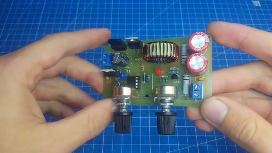
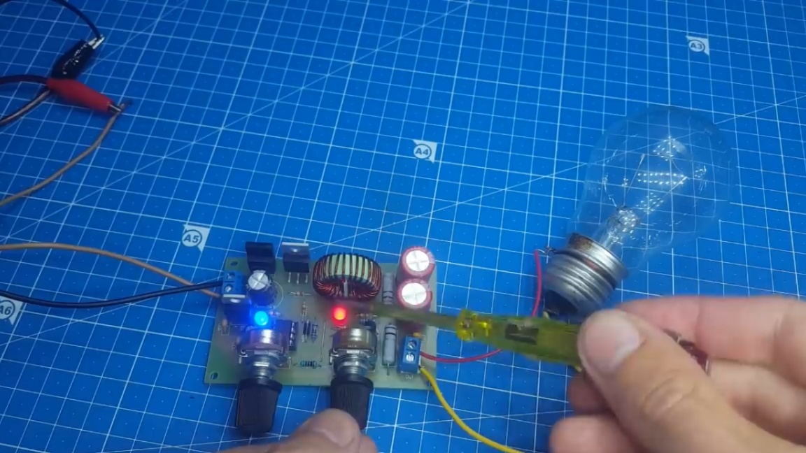
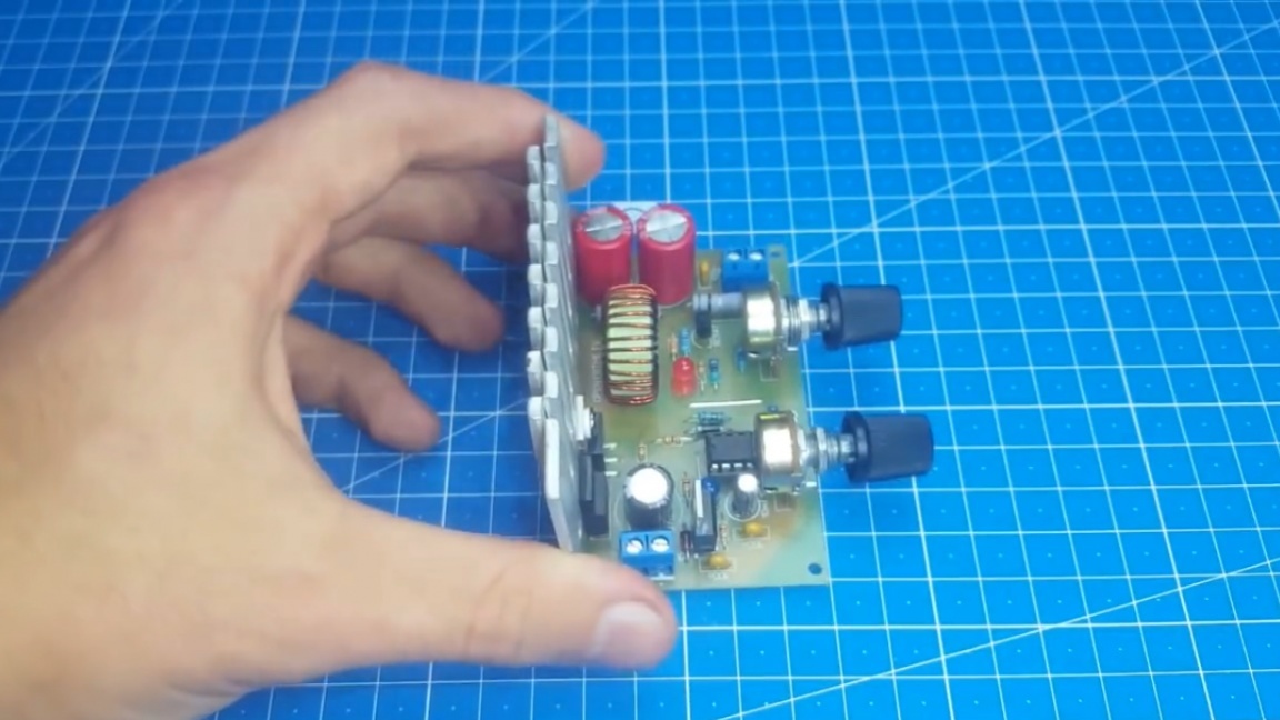
Not so long ago, Roman made a dc-dc converter on this chip, and he really liked it at work. A minimum of components, good performance, all this prompted the author to create a power supply on this chip. As you can see, a simple and compact board came out.
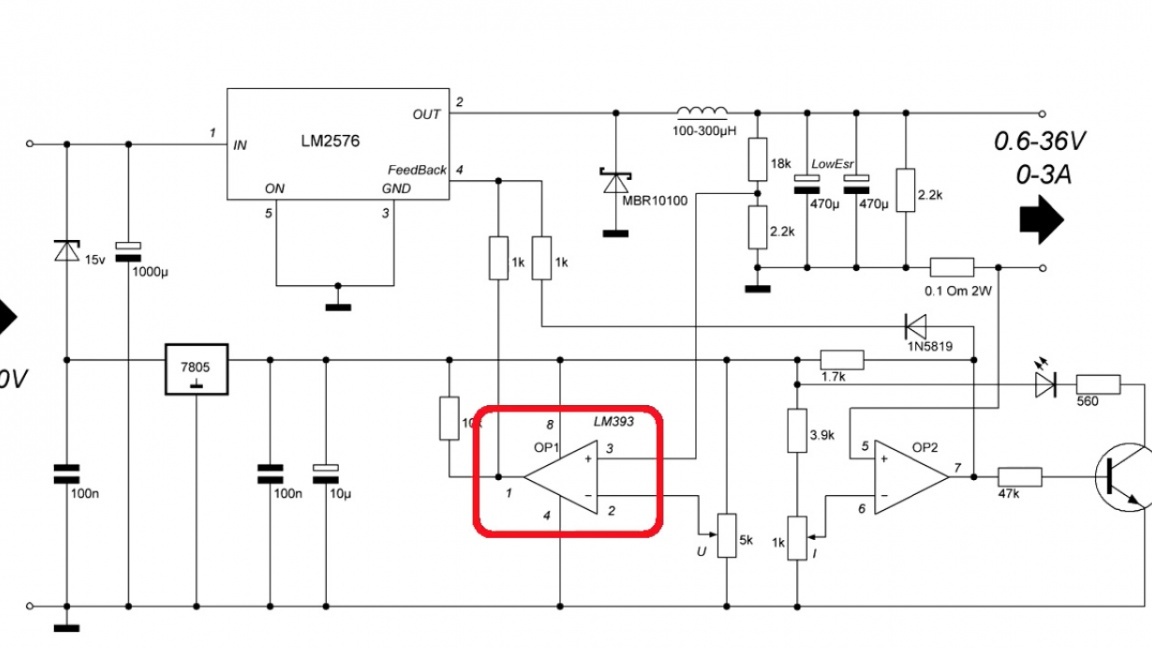
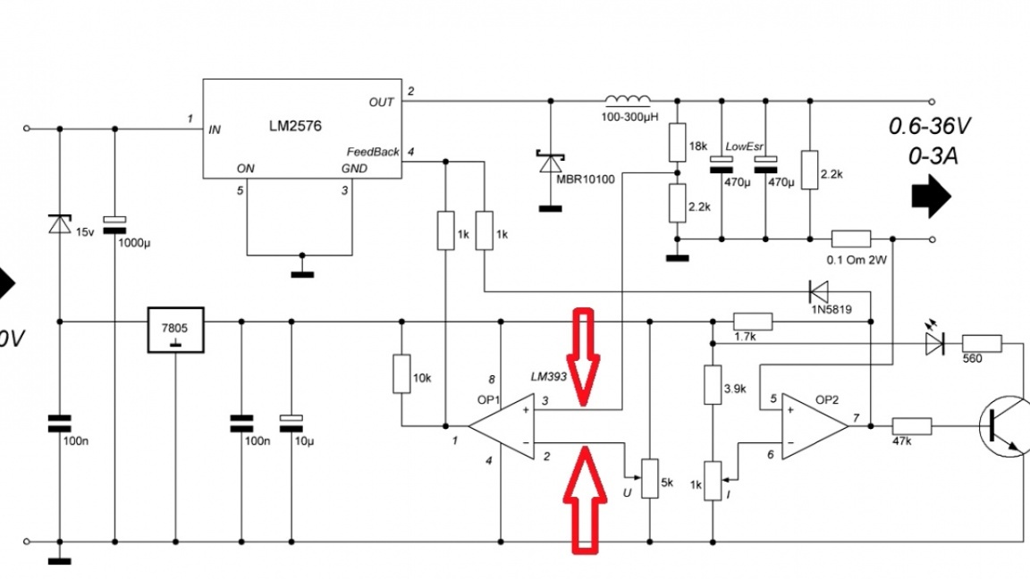
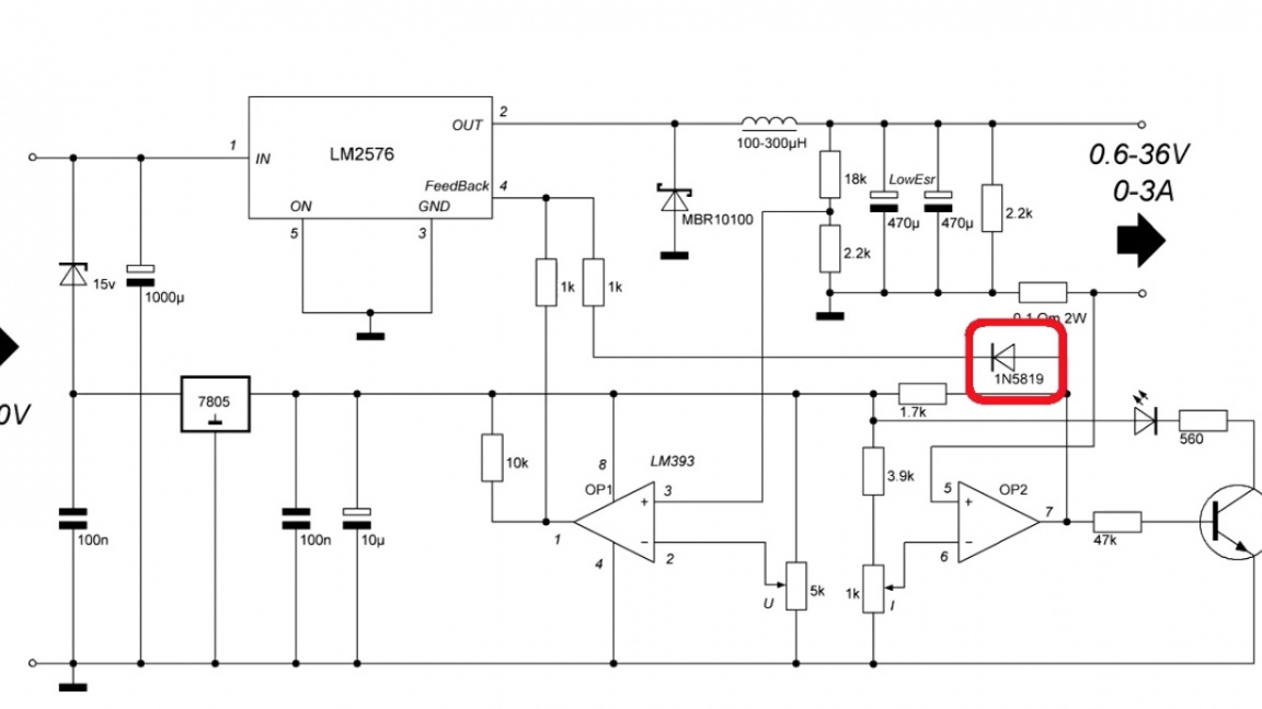
So, let's look at the diagram right away.
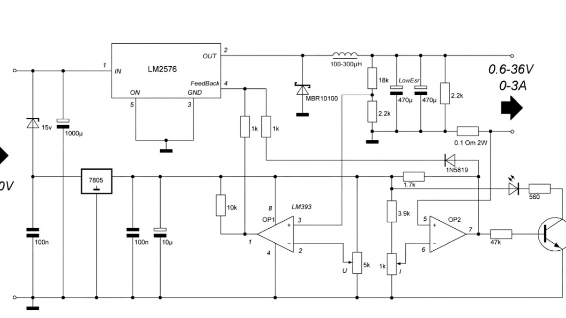
The topology is similar to what the Chinese offer in their dc-dc converters.
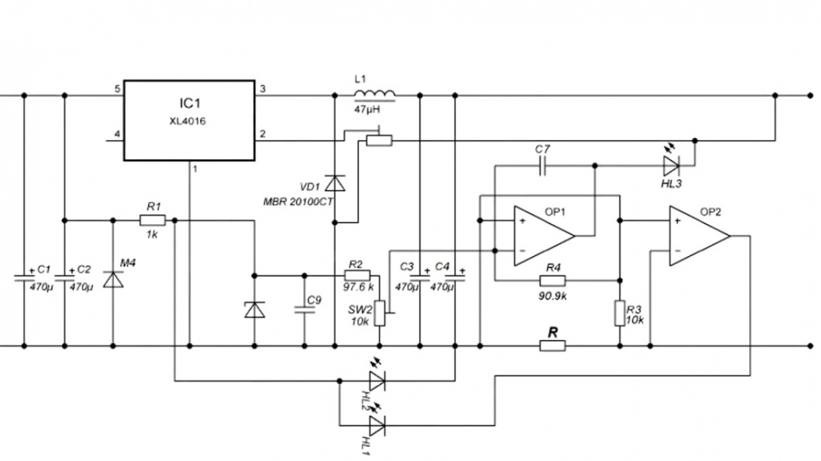
Only here, both operational amplifiers affect the chip.
This solution adds stability to the work. We also see the current limit indication. A convenient thing, especially if you assemble a laboratory power supply.
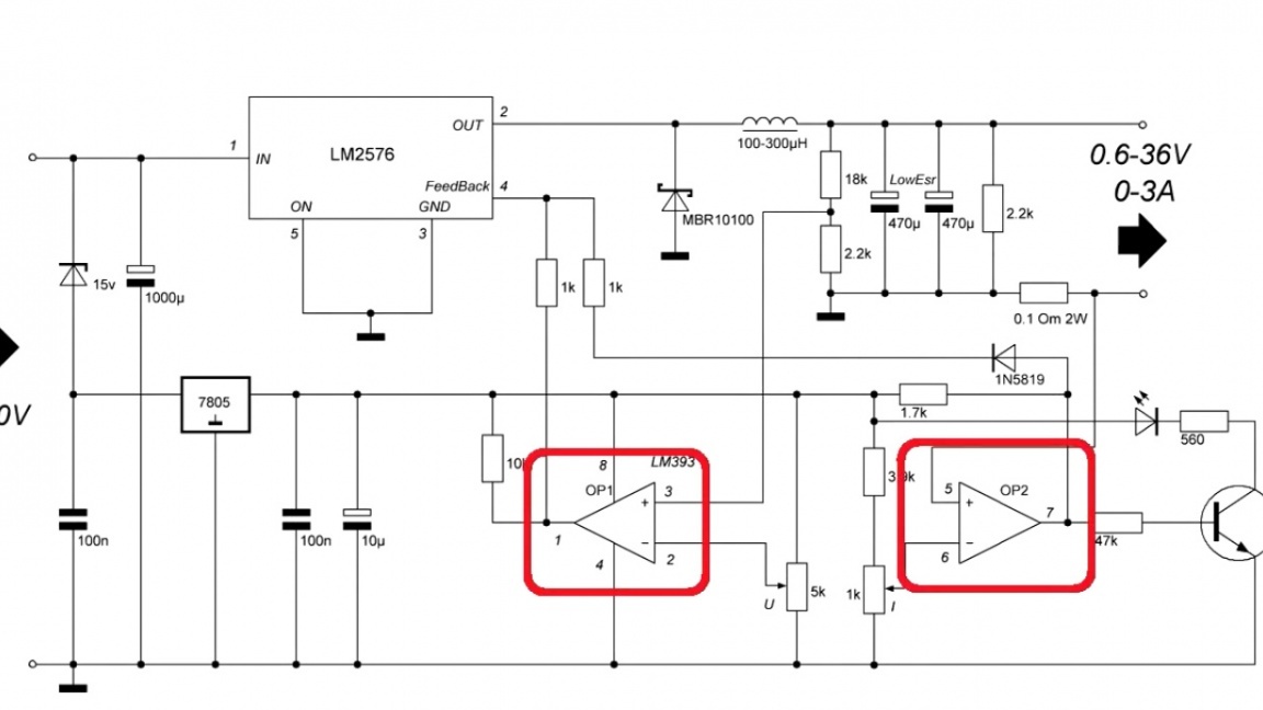
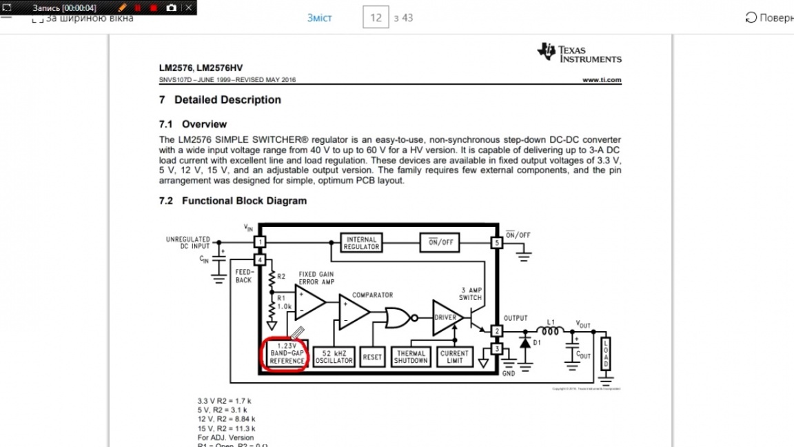
And now a few words about the operation of the circuit. At the moment of switching on, there is no voltage on the fourth output of the microcircuit, and it begins to increase the pulse width.
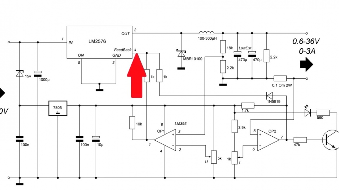
This will happen until a voltage of 1.2V comes to the fourth output. Why is that? That's because such a topology of the chip itself.
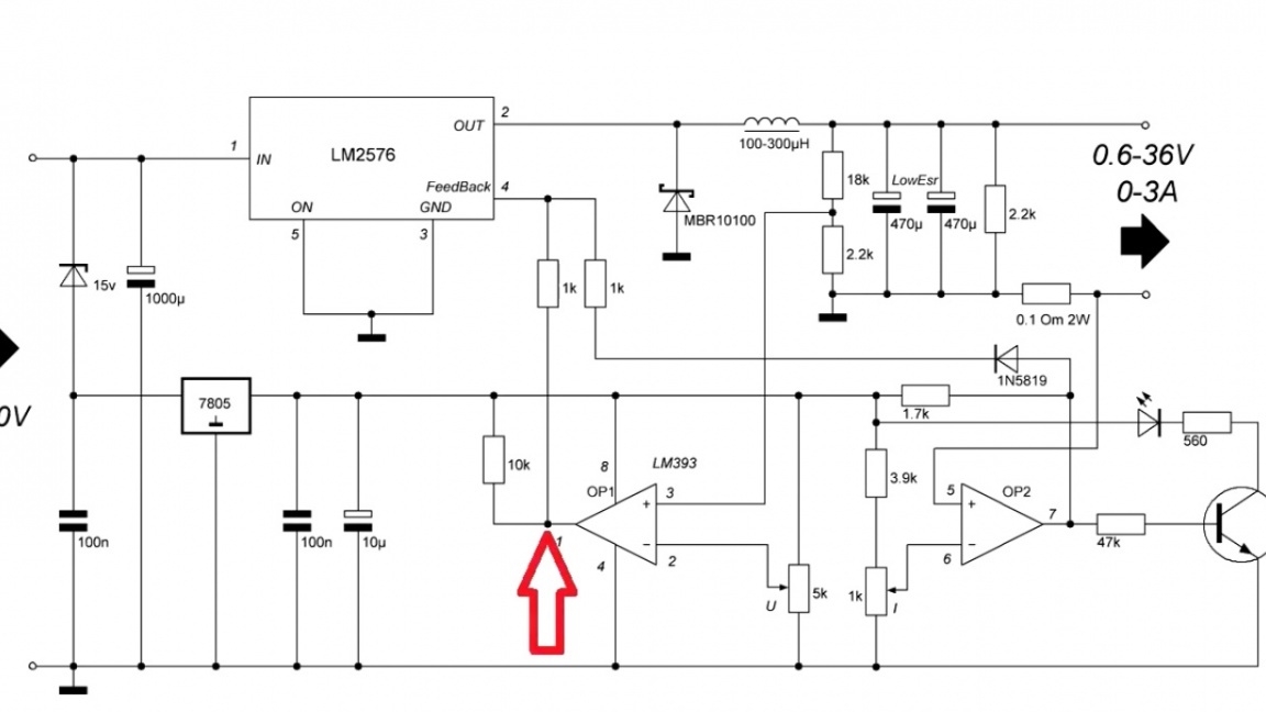
Now let's look at what op amps do with the example of the first.
As you know, one of the features of an operational amplifier is that it tries to equalize the voltage at its inputs.
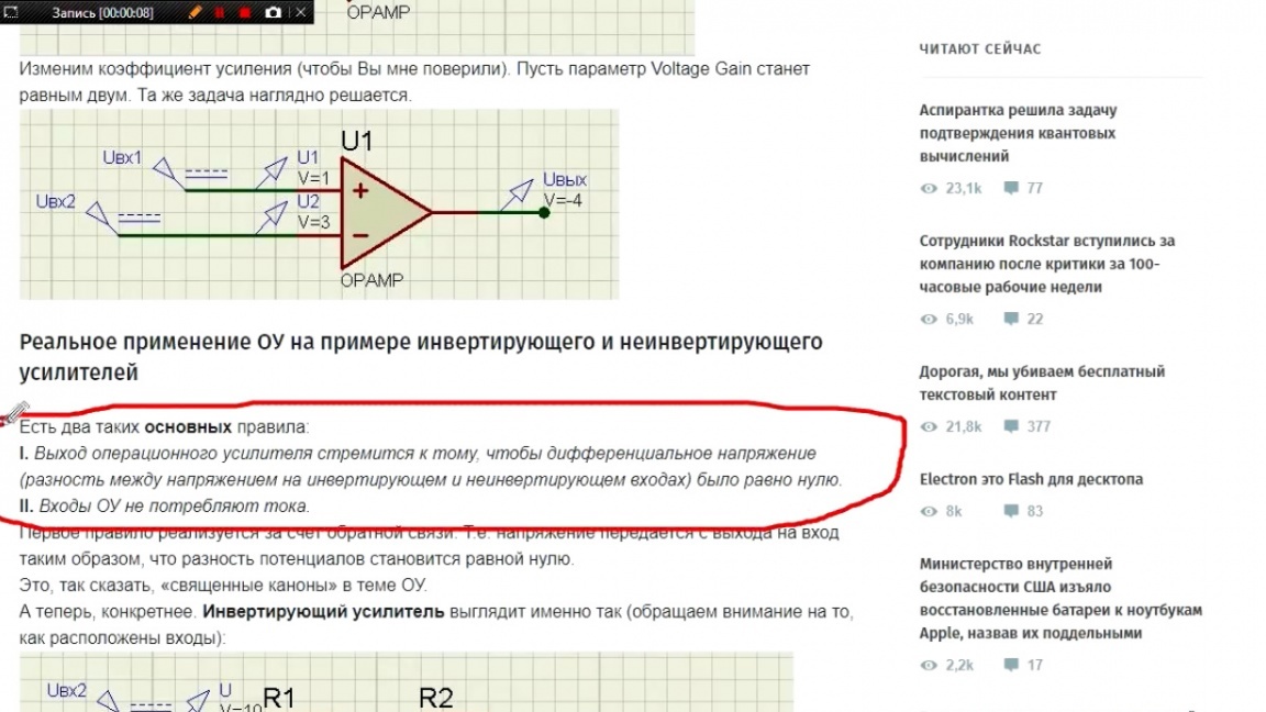
So, we set a certain voltage with a variable resistor, and now the operational amplifier will either increase or decrease its output voltage until the voltage at the inverting input and at the inverting input are equal.
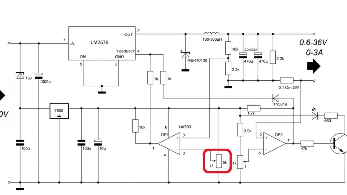
The second operational amplifier monitors the voltage drop on the shunt.
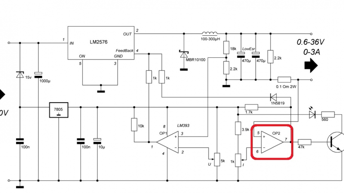
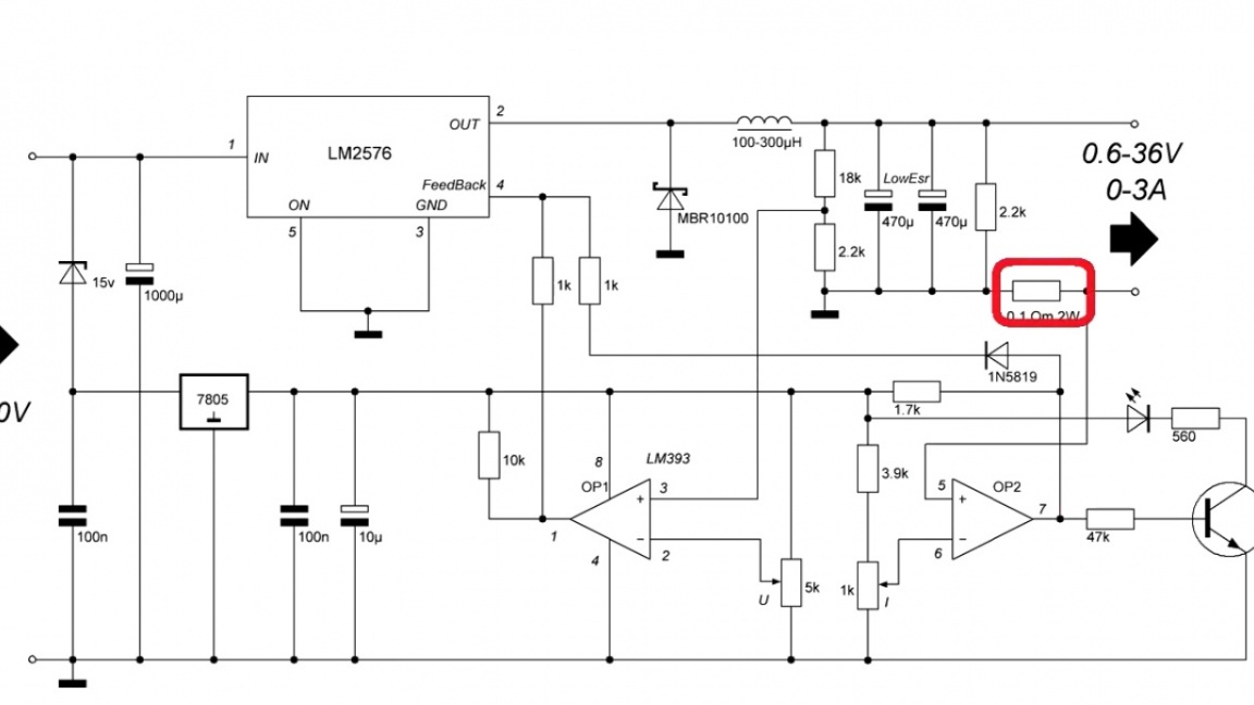
And as soon as it becomes the same as the reference one, the voltage at the output of the operational amplifier will begin to increase until a predetermined current is established.
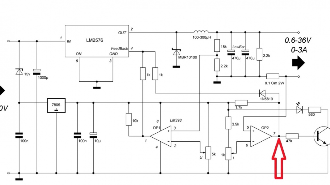
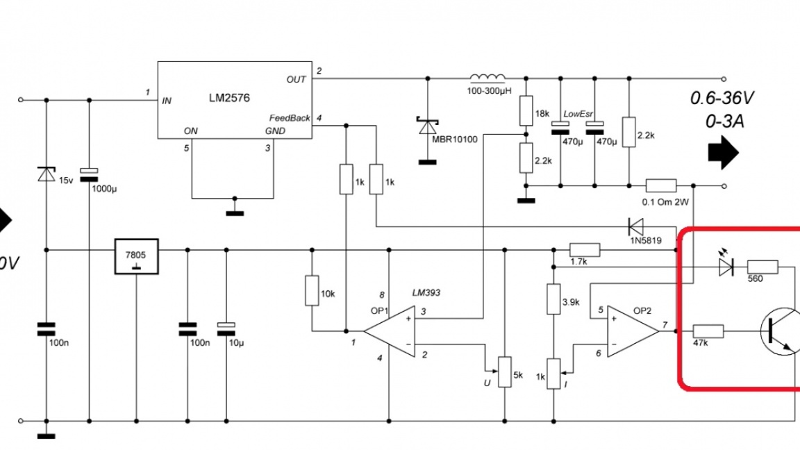
The diode is installed to exclude the influence of operatives on each other.
Also in the circuit there is a zener diode. It is needed in order to reduce the voltage by 7805.
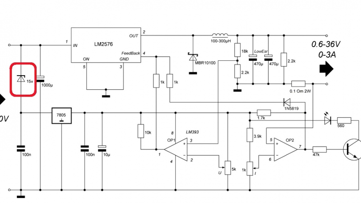
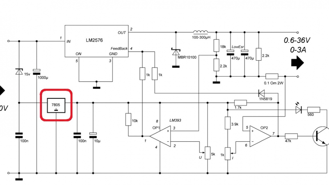
If the supply voltage is less than 22V, then it can be replaced with a jumper.Well, I think questions on work should not arise.
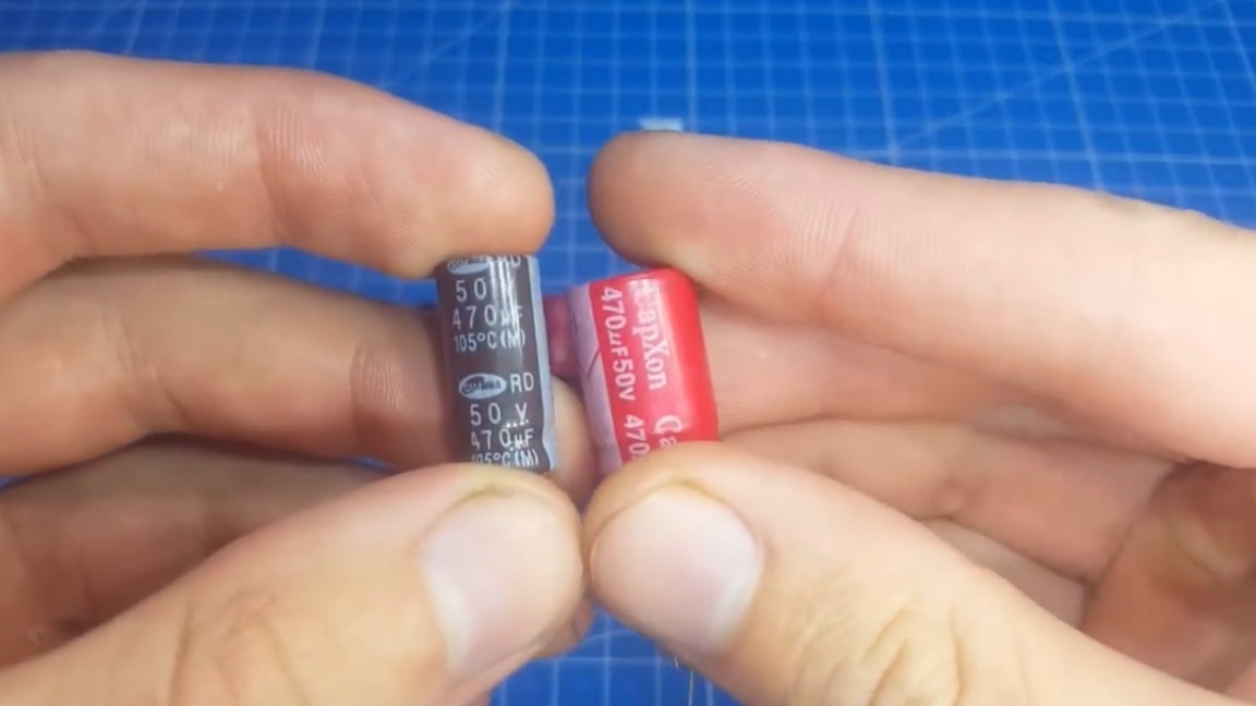
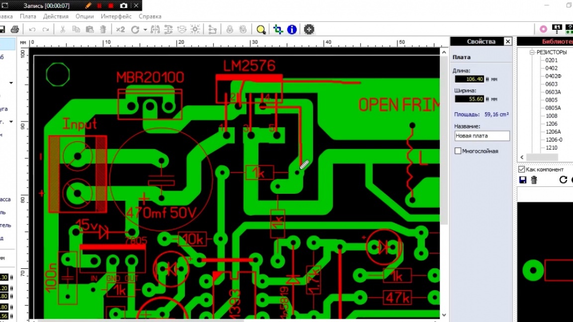
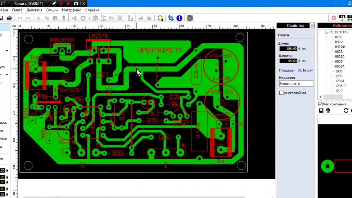
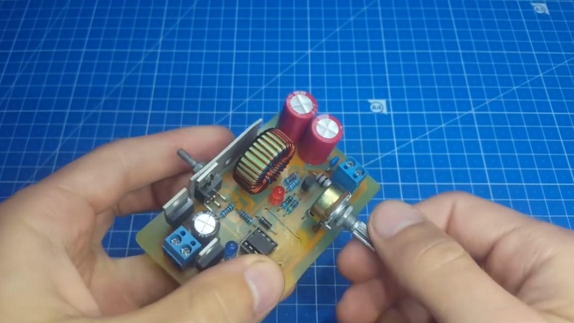
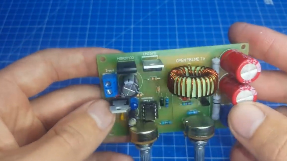
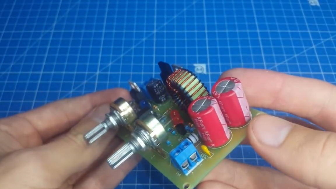
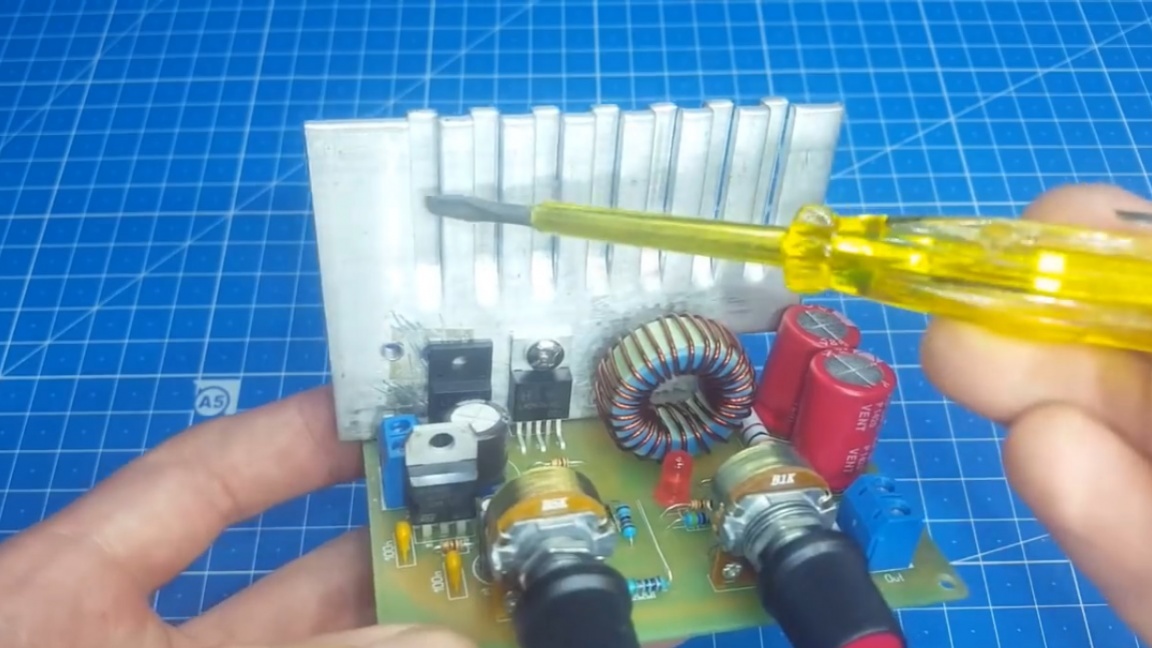
So, when you figured out the circuit, as always, you should talk about the printed circuit board. Immediately striking is the use of 2 output capacitors.
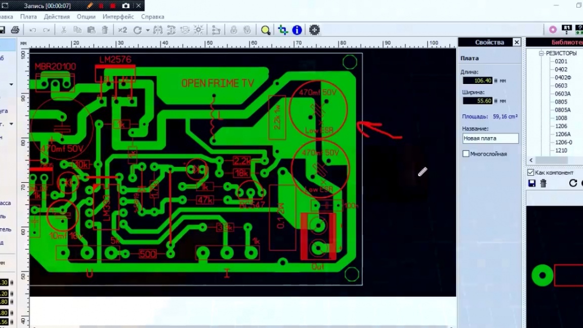
The author did so for reasons of compactness. These capacitors must be Low ESR, and as you know, their size is larger than ordinary. Therefore, the author put 2 such capacitors of 470 microfarads each.
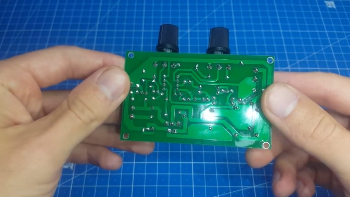
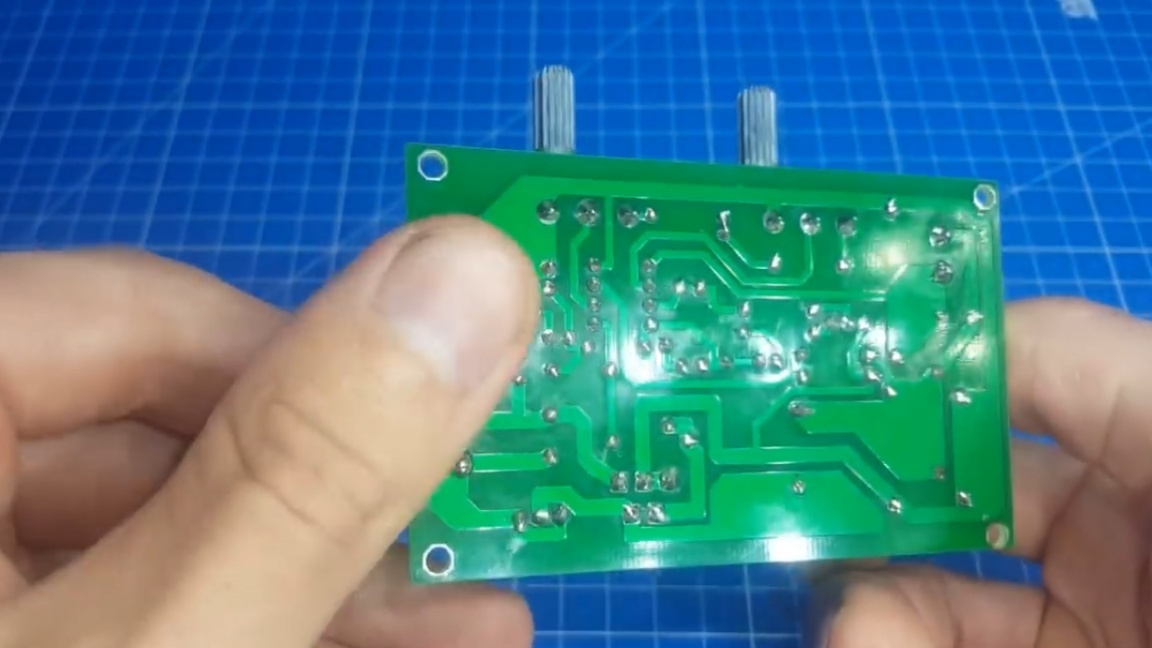
You should also pay attention to the correct layout of the printed circuit board. It consists in the fact that the control wire must not be crossed by force, since there will be interference and the stability of work will be lost.
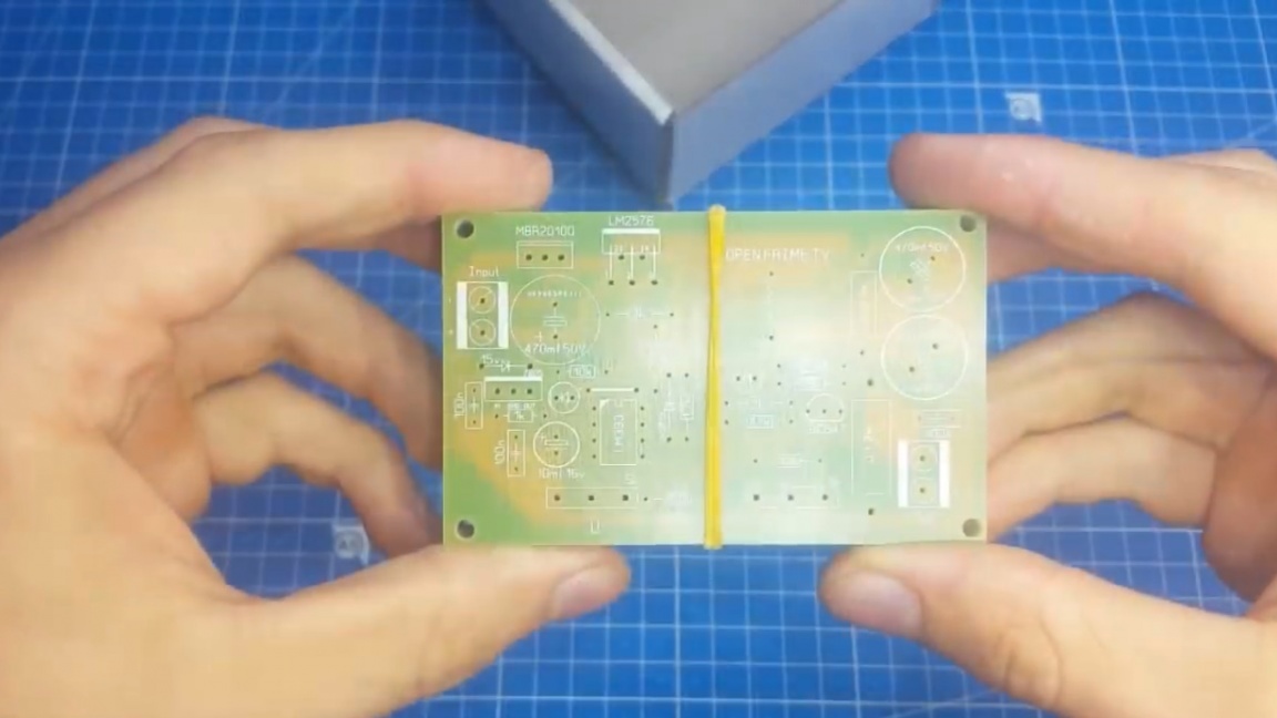
The author, as always, first made a trial version of the circuit using the LUT method, checked it on the jambs, especially the left and right rotation of the resistors, and then ordered a printed circuit board for manufacture in a Chinese company.
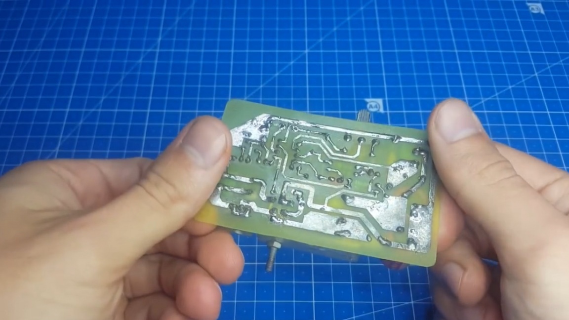
And now the boards arrived, they are of always excellent quality and beckon them to solder. Well, let's not deny ourselves such pleasure and solder one of them.
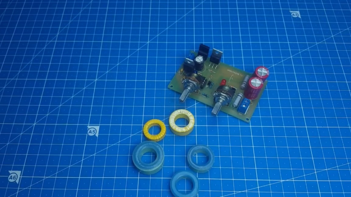
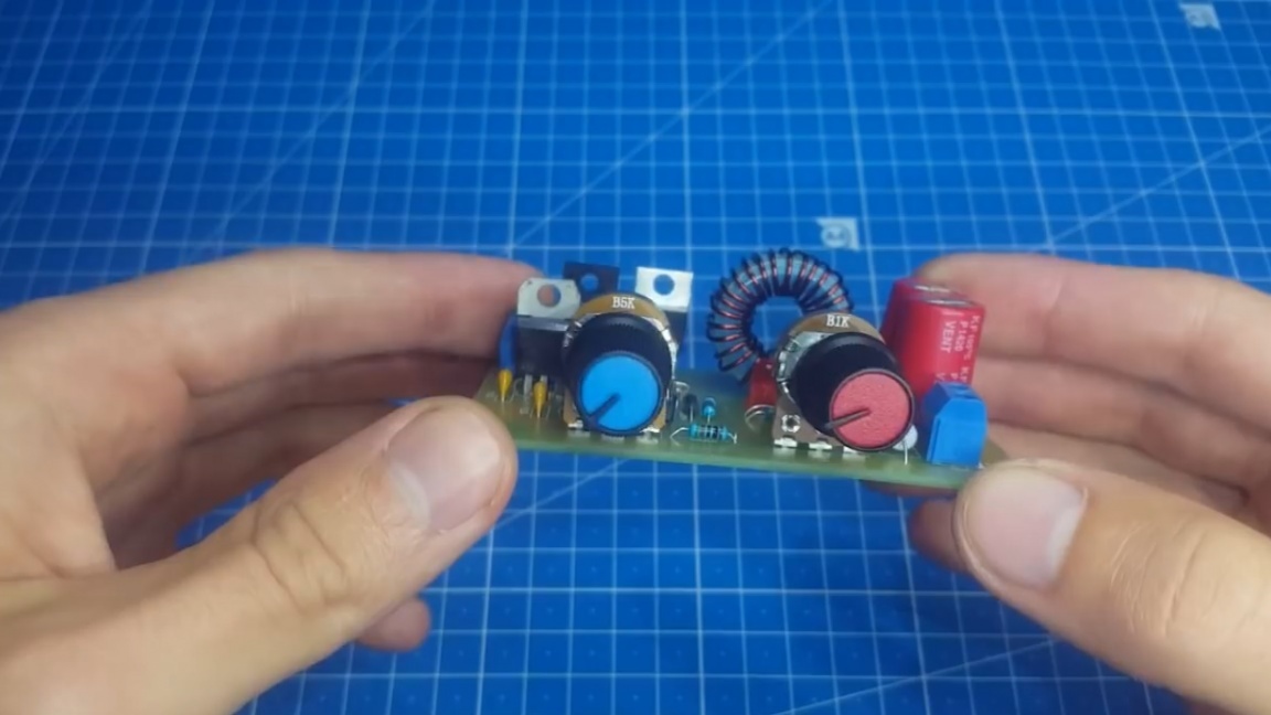
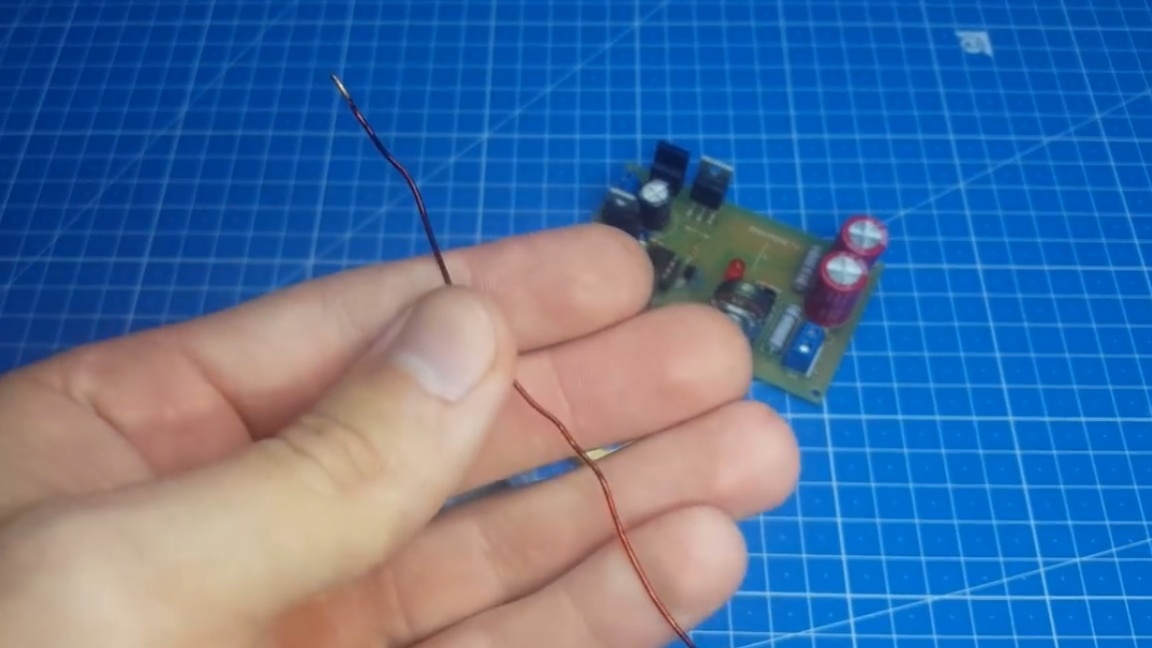
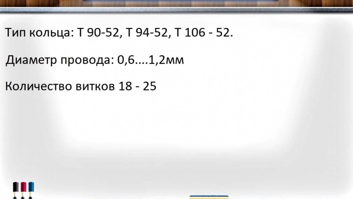
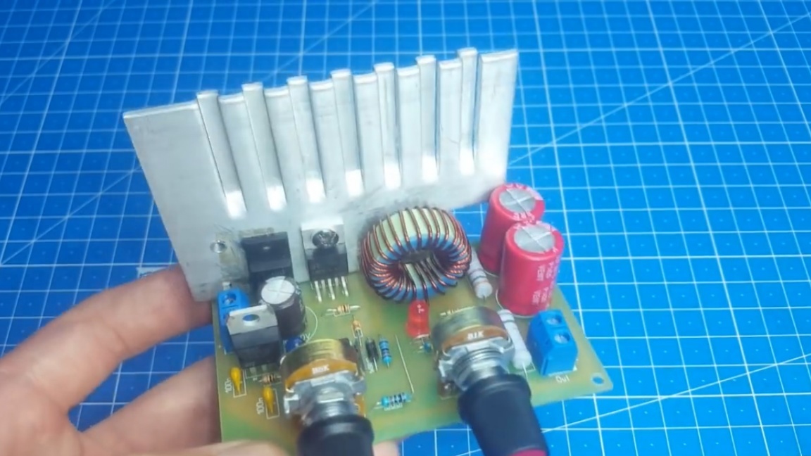
And now, everything except the throttle was soldered, it must be wound. As a base, rings of such types T 90-52, T 94-52, T 106-52 are suitable, well, or well, everyone’s favorite rings from computer power supplies.
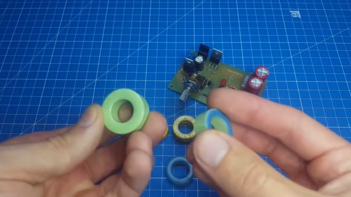
For winding, we need a wire with a diameter of 0.6 to 1.2 mm. The number of turns can vary from 18 to 25.
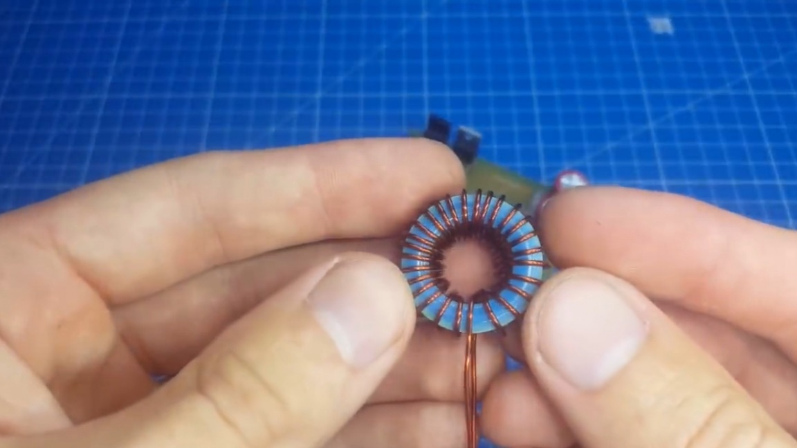
We wind evenly around the ring. As a result, the throttle should look like this:
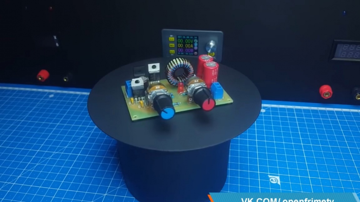
We complete the assembly of the board and now it is necessary to carry out tests. For this we need a power source. The DPS5020 is excellent here, since it displays all the parameters on the screen and is easier to follow.
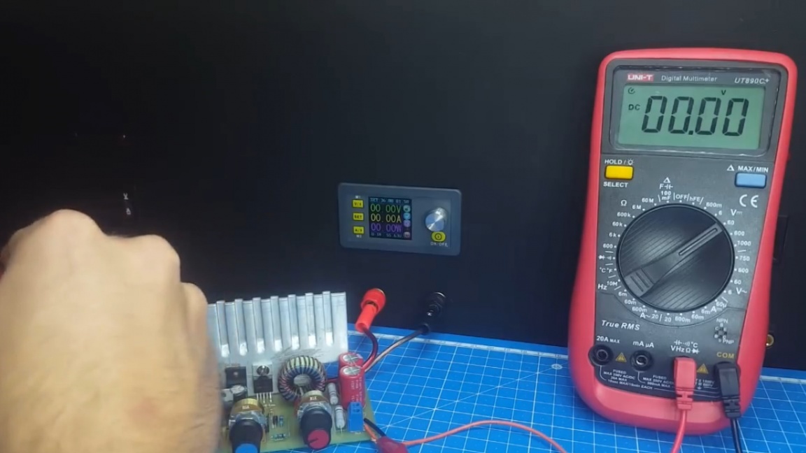
First of all, check the voltage adjustment.
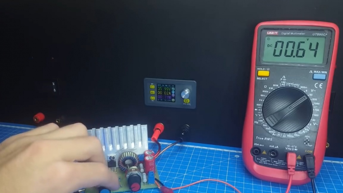
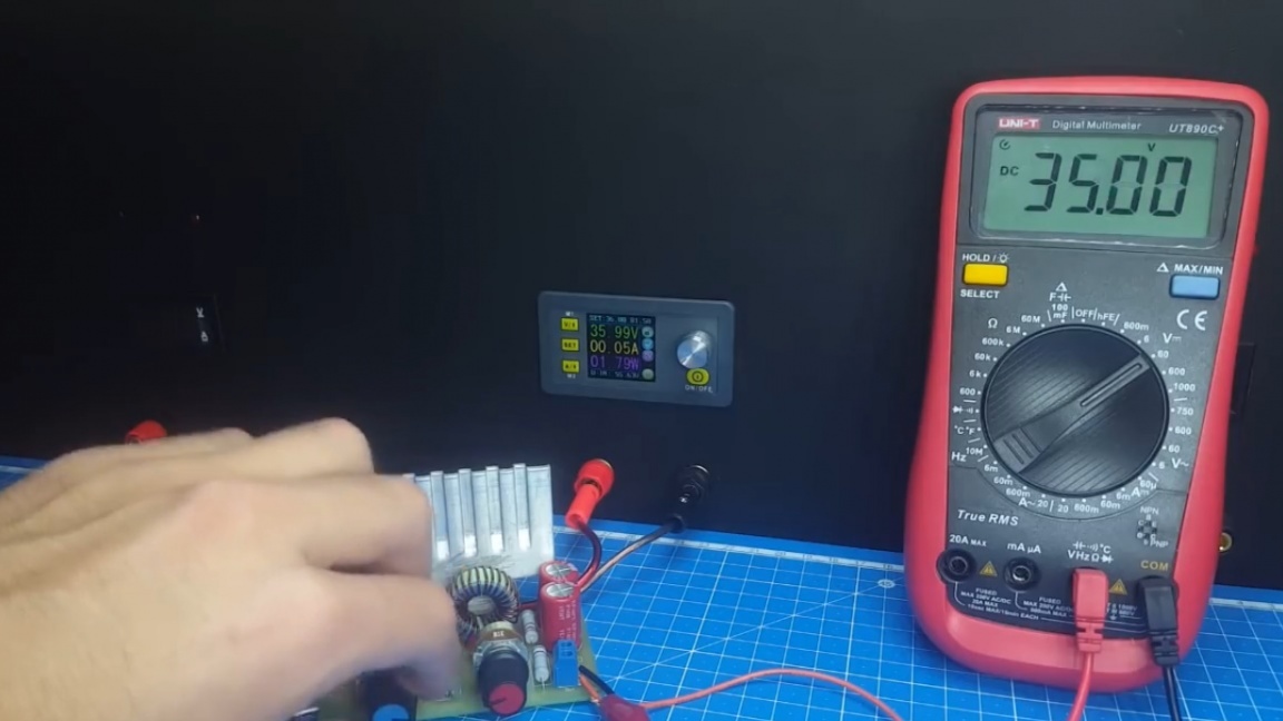
As you can see, the minimum voltage is about 0.6V. It could still be reduced, but then there is instability in work. The maximum voltage at the output is almost equal to the input, but it is without load, it will sag a little with it. Now check the current performance of this circuit. For this we need this electronic load that the author made earlier do it yourself.
Set the output voltage to 15V and load with a current of 3A.
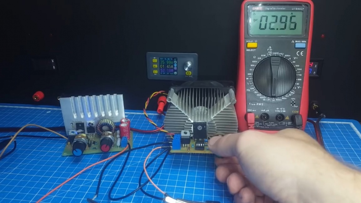
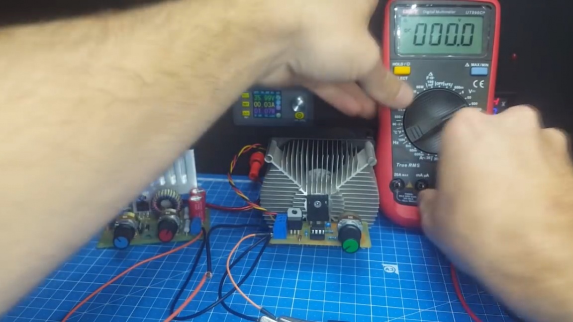
As you can see, our homemade power supply does an excellent job. You may have noticed the heatsink on the chip. Yes, although this is a switching power supply, but its efficiency is not 100%, it also heats up and therefore it cannot be used without a radiator.
Well, in the end we got an excellent adjustable power supply on the LM2576 chip, which is suitable for those who do not chase high currents, and a 3 amp head is enough to test almost any circuit.
Thank you for attention. See you soon!
Video: