
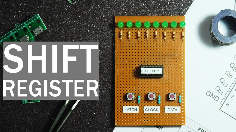
After low level study bench HD44780having won the first prize at one of the competitions, the author of Instructables under the nickname indoorgeek decided to make another similar stand. This time, the user who wants to feel in the shoes of "living Arduino”, It is possible to control the shift register - an important component of matrix LED displays and not only.
The device uses the shift register 74HC595, which is most often encountered in the practice of the arduino, and you can also use the compatible KR1564IR52. Using three of these microcircuits, for example, you can turn five outputs of a microcontroller into twenty-four! And the proposed homemade It will clearly show you what processes are taking place.
Indoorgeek assembled such a stand in two versions: on a regular breadboard and on a breadboard, like this:
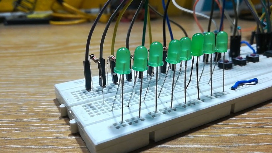
You can do it as you like, or even apply volumetric installation or make a printed circuit board. It is much more important not to make mistakes during assembly than to argue about its methods.
The components in the design are as follows: one shift register of the type indicated above, a socket for a 16-pin microcircuit (you can do without it), eight LEDs, the same number of single-ohm resistors, three ten-ohm resistors, three buttons, as well as an adapter card with a Micro socket USB If you have very straight arms, you can just take the Micro USB jack and solder two wires to it. And if you don’t like to be original, you can just use a cord with a regular USB connector. Only the polarity in all cases, do not confuse, well, do not arrange a short circuit.
Our shift register is scientifically called an eight-bit shift register with three states. The first means that it has eight one-bit memory cells and the same number of outputs, and the second - that each of the binary bits can take one of three states: zero, one, and high impedance. This is not a curse, but an imitation of a cliff, as if it were not connected at all. An output in a high-pitched state, as they say, does not interfere: you can pull it with a resistor to at least zero, even to unity, and he dutifully “agrees”. But if he goes into a state of zero or one, it will receive priority, since the low output impedance of the microcircuit will overpower your resistor.
The microcircuit has five inputs.As the reader probably already guessed that with such a small number of inputs to get so many outputs, you need to receive information in series, and output it in parallel. You type in the same way on the keyboard or write on paper in turn letter by letter, and then you see all the text at once. If you connect several shift registers in series, you can increase the number of outputs by the corresponding number of times, but at the same data transfer speed, the long chain of registers will fill up longer. Analogy: it takes more time to write down several sheets of paper than to fill up just one at the same speed.
But the shift register is different from paper in that the data in it is automatically shifted, hence the name. You write the next bit into it, and all the previous ones are moved further into the register or their chains, the same one that was at the end before it disappears. Imagine a tube filled with balls, some of which are ordinary, others are luminous. Put the next ball in it - normal or luminous, and another ball will fly out from the opposite side.
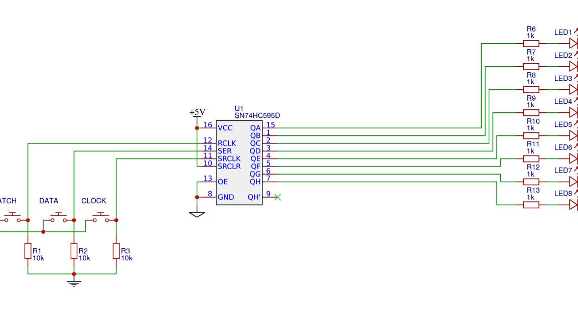
Let's get acquainted with the purpose of the inputs of the chip. For some reason, indoorgeek decided to list them in reverse order, as before launching a spacecraft. The 14th pin is needed to enter serial data. It is like a tray on which you place a regular or luminous ball before pushing it into the tube. 13th conclusion - the inclusion of outputs. If zero is applied there, the outputs will turn on as if the handset had become transparent. We give one - and the tube has become opaque, what balls and in what order the tube is filled, is not visible. That is, all outputs of the shift register went into a high impedance state. In the construction under consideration, this conclusion is always pulled to zero, which is equivalent to always a transparent tube. The 12th conclusion is a type of shutter of the camera. When there is zero, the picture that the viewer sees through the tube does not reflect the actual state of the balls in it, but the one that was observed when the unit was last seen on this conclusion. If there is one, the movement of the balls in the tube can be observed in real time. For all this to work as described, in the microcircuit, in addition to the shift register, there is a storage register. The 11th conclusion is clocking, that is, pushing the ball from the tray into the tube. We feed there the unit at the moment when the value we need is on the 14th output, and, without removing it from there, we remove the unit from the 11th output. The 10th conclusion is a reset. If zero is applied there, this will be equivalent to the loss of luminous properties by all the balls in the tube. By submitting a unit to the reset input, you can start to fill the tube again with ordinary and luminous balls in any order, as described above. In the stand under consideration there is always a unit. Conclusion 15, as well as conclusions 1 through 7, are the outputs of the shift register. Power is supplied as in most sixteen-pin digital circuits: 8 - common wire, 16 - plus five volts. Finally, pin 9 is the exit to the next shift register, which can be connected in series to several pieces, as if you made one long tube from several short ones. In general, we connect pin 9 of the previous register with pin 14 of the next and rejoice. You can so improve the proposed homemade product.
Since this is the second stand for indoorgeek, the phobia in front of the pull-up resistors, which was described in a previous article, is slowly disappearing from him. Here there are already three of them, which allowed us to use normally open buttons instead of the toggle buttons. 10-kilo-ohm resistors were used as pull-ups, and 1-kilo-ohm resistors for LEDs. As in the previous design, parallel to the clock button (11th output), it is good to connect a capacitor of 100 microfarads and at least 6.3 V plus to the plus of the power supply, and minus to the microcircuit and resistor. It will turn out the simplest contact bounce suppressor.
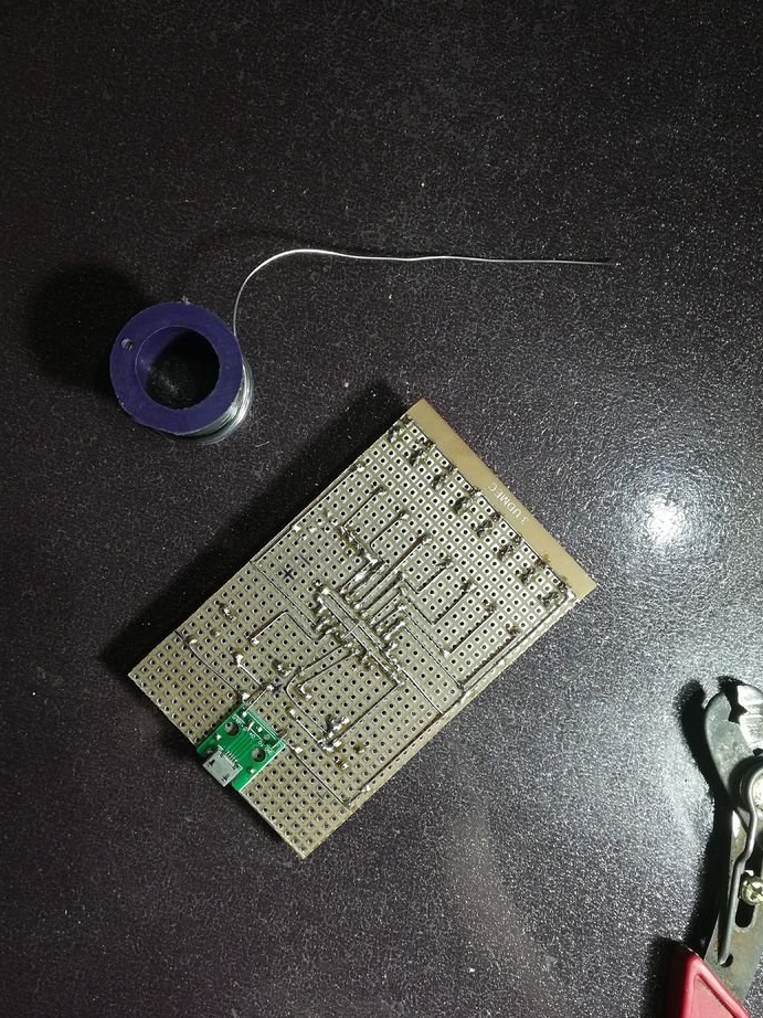
Repeat after indoorgeek:
So you also succeeded:
Now how to use it all. To put a luminous ball into the tube, press the button connected to terminal 14, after which, while holding it, press the button connected to terminal 11, and then release it. Next, release the button connected to pin 14.To do the same with a non-luminous ball, with a button connected to terminal 14, we do nothing, and press and release the button connected to terminal 11. So you can write in the shift register and a few bits. In both cases, when the button is released, connected to terminal 12, the state of the LEDs will not change, and when pressed, it will reflect the state of the shift register in real time. If you decide not to keep this button pressed during recording, briefly press it now, and the storage register will take a picture of the current state of the shift register.
Since the tube and balls are virtual, and the microcircuit and LEDs are real, for the viewer, each ball falling from the opposite side of the tube disappears. There would be another register, he would move there. You can improve this design by adding this register, and even several of them, and eight more LEDs with resistors for each of them. As indicated above, pin 9 of each previous register must be connected to pin 14 of the next. And the power supply and inputs 10, 11, 12 and 13 of all the registers are parallelized.
So you got an idea of what operations Arduino does by controlling shift registers.