Do not rush to throw away the old laptop battery, you can make a bank out of its elements. How the Master did this, we will consider in this article. The claimed characteristics of the power bank 6600 mAh 5V. If necessary, the battery capacity can be increased.
Tools and materials:
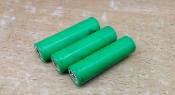
- Lithium-ion batteries 18650;
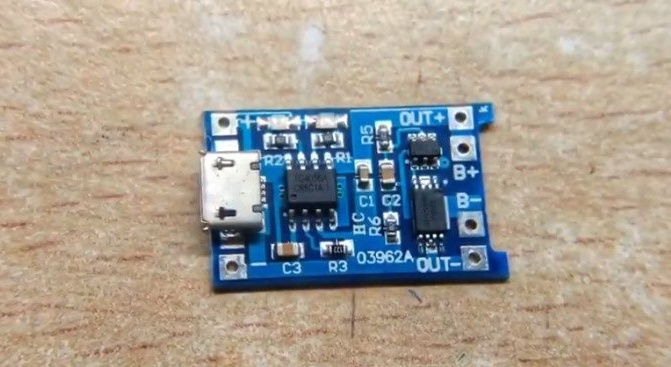
-Charge module TP 4056;
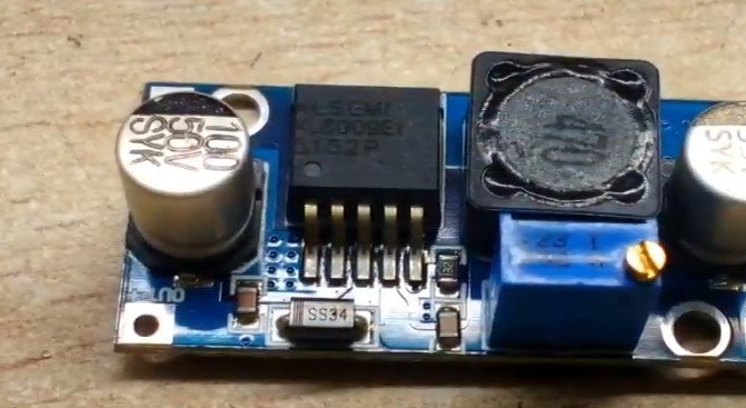
-Increasing XL6009 converter;
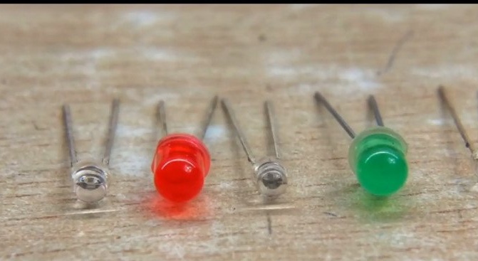
-LEDs;
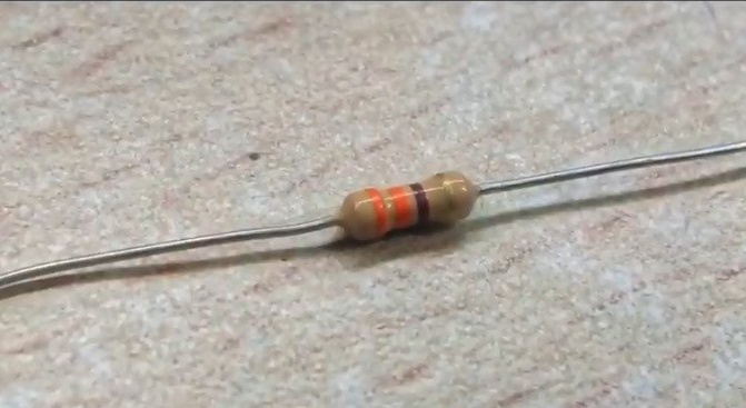
- Resistor 330 Ohm;
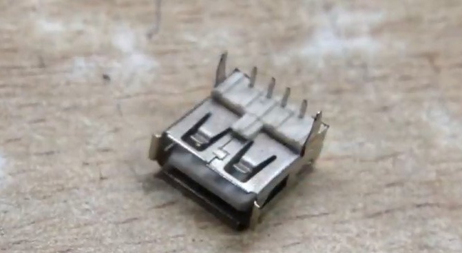
-USB socket;
-Soldering accessories;
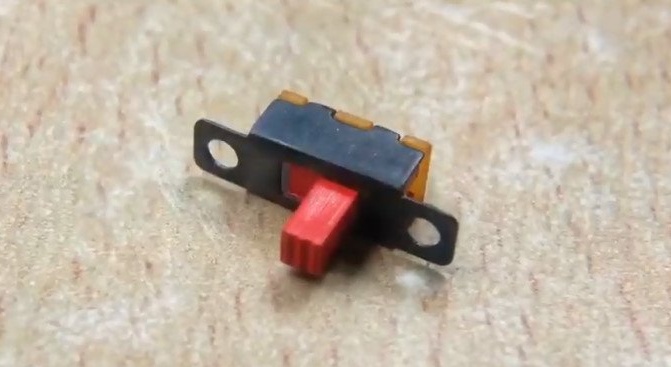
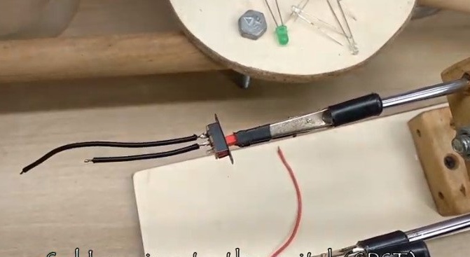
-Switch;
-Plywood;
-Drill;
-Circular Saw;
-Glue;
-Hacksaw;
-Clamp;
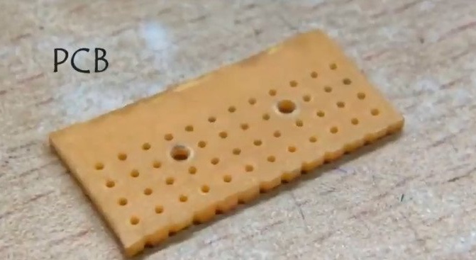
-Circuit board;
-Insulating tape;
-Multimeter;
-Glue gun;
-Varnish;
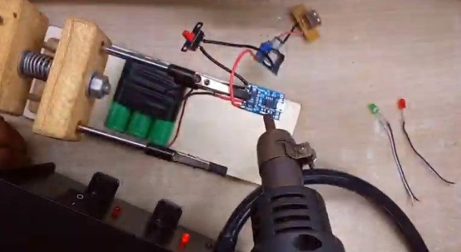
Step One: Making a Battery Pack
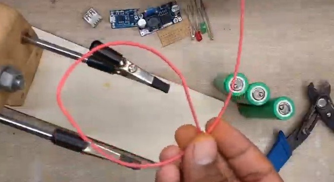
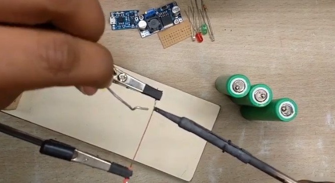
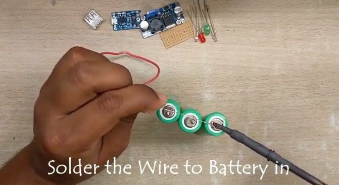
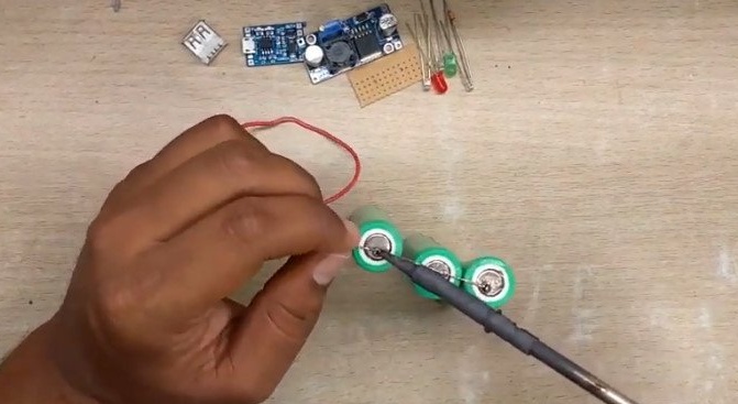
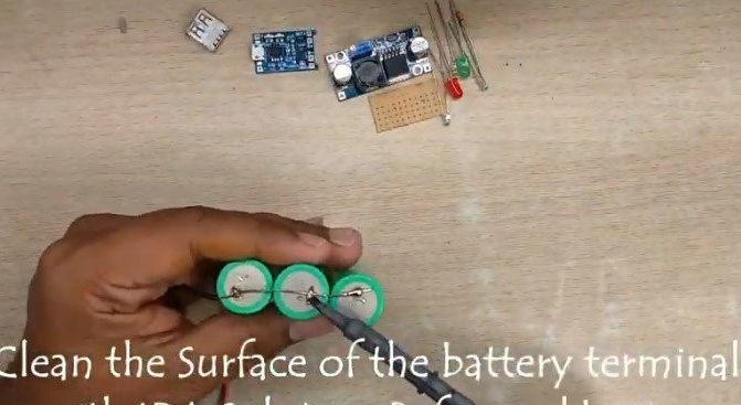
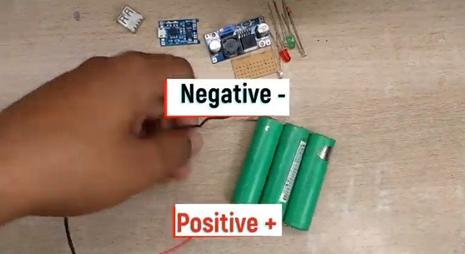
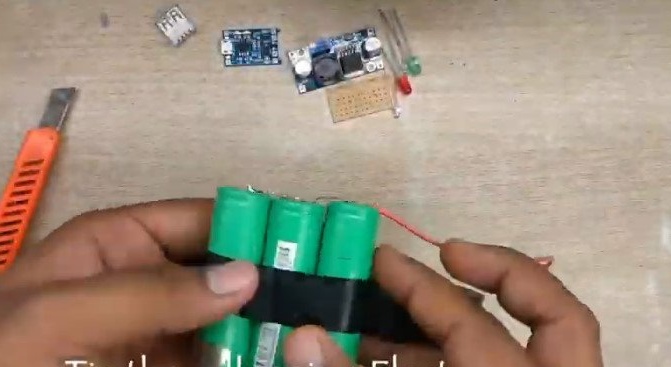
Having disassembled the battery, the master selected three serviceable batteries. It strips the wire from insulation and solders the solder. Solder the red wire to the positive terminals of the batteries, and the black to minus. To fix it, wrap the battery with electrical tape.
Before installation, it is necessary to charge the batteries to the same voltage. When soldering, it is important not to overheat the batteries.
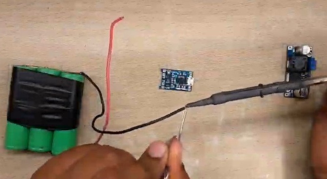
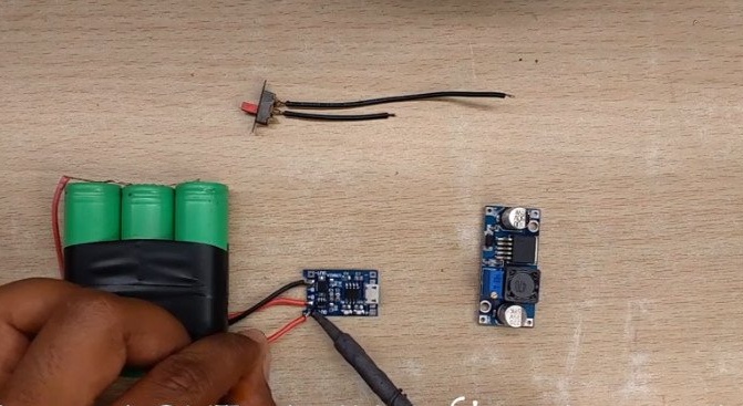
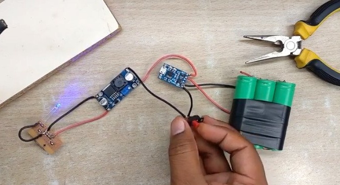
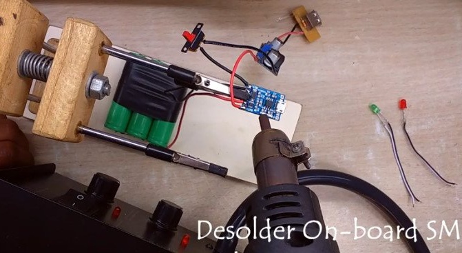
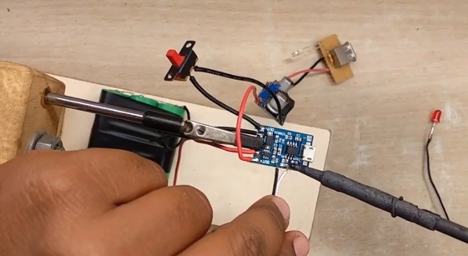
Step Two: Charge Module
In the device, the master uses the TP4056 charge module. The TP4056 module protects the battery against overcharging, discharging, and short circuiting. Lithium batteries should be handled with care. The voltage level should be in the range of 2.7 to 4.2 V.
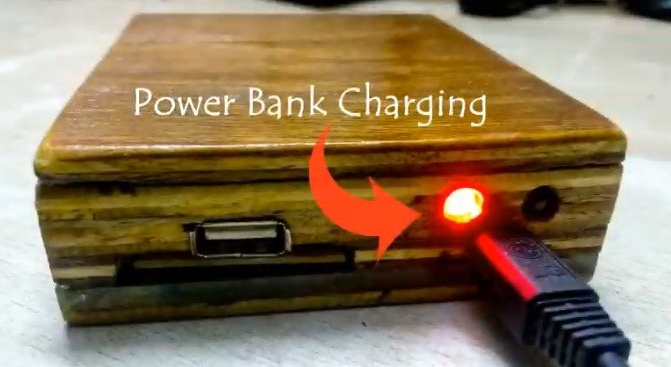
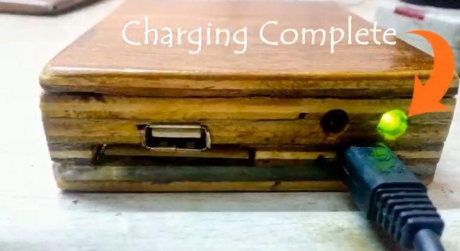
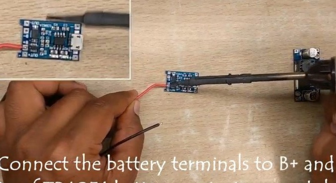
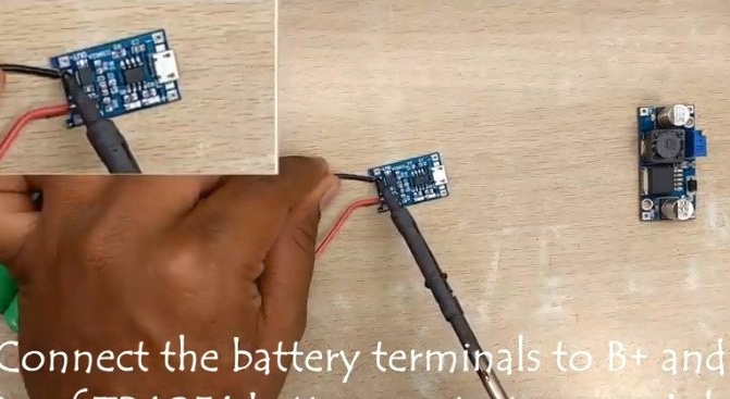
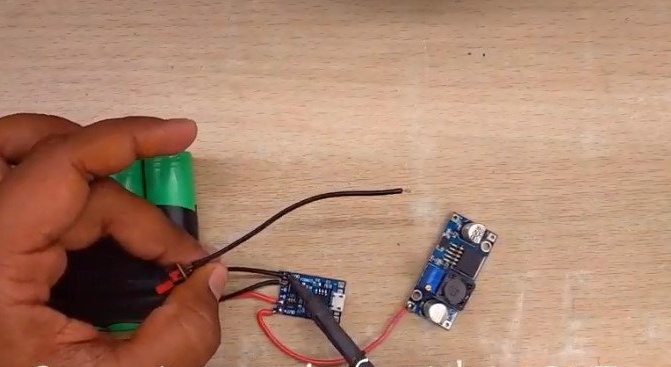
The battery is connected to terminals B + and B-. Batteries are charged by any USB mini charger. The LEDs on the board indicate the state of battery charge: red LED indicates charging, green indicates the battery is charged.
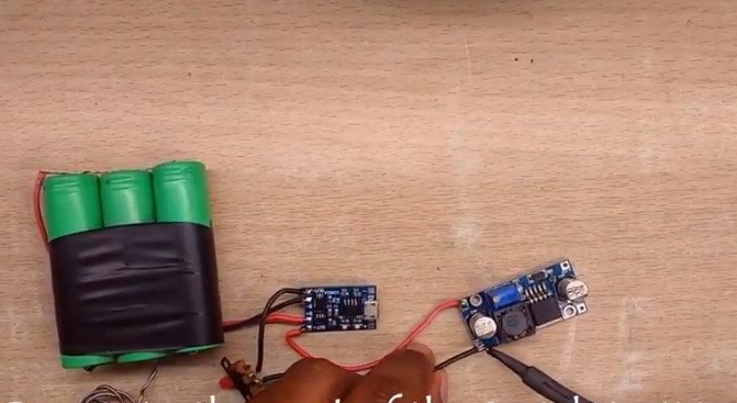
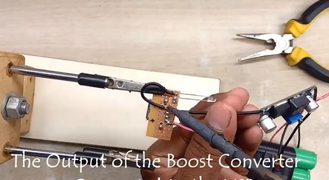
Step Three: Boost Converter
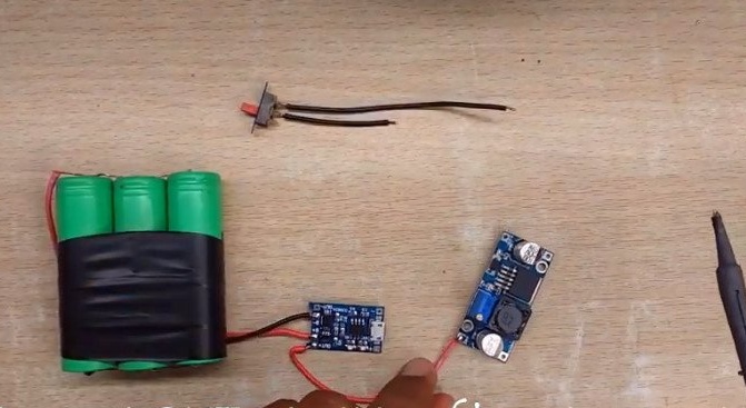
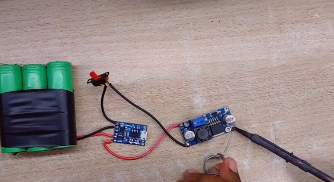
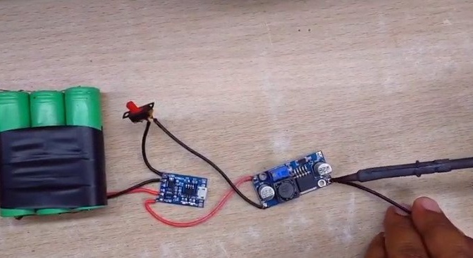
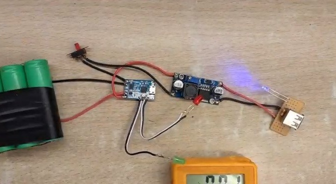
In this scheme, the module serves to increase the voltage from 3.7 V to 5 V. It connects the Out + and Out + of the charging module to the IN + and IN- modules of the boost converter. A circuit breaker is installed between the modules.
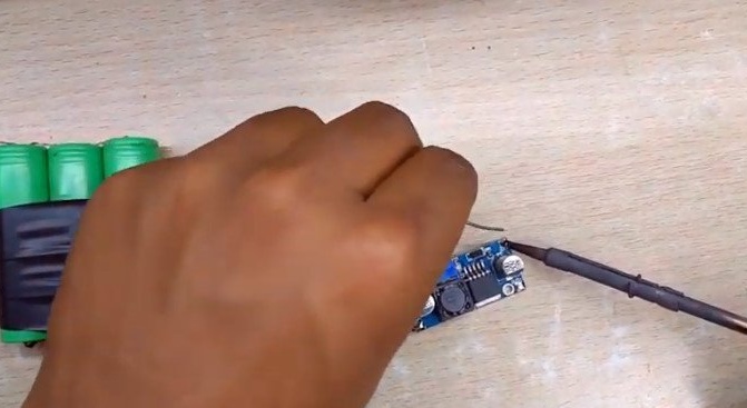
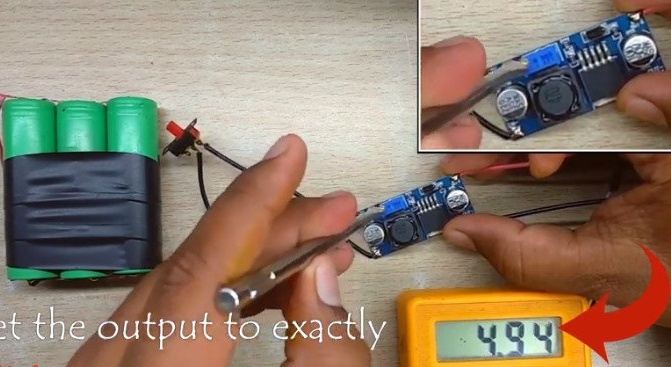
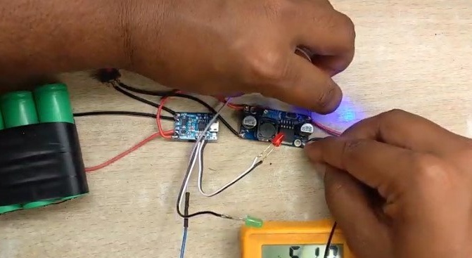
After assembling the circuit, it is necessary to set the output voltage to 5 V.
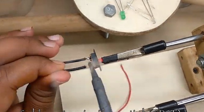
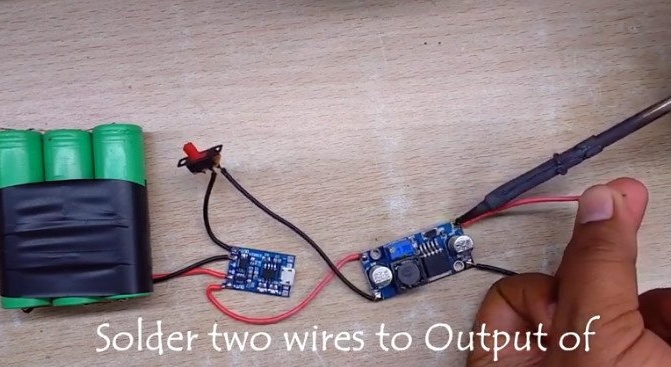
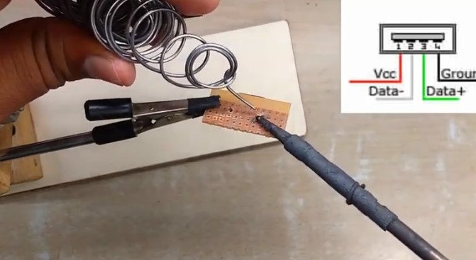
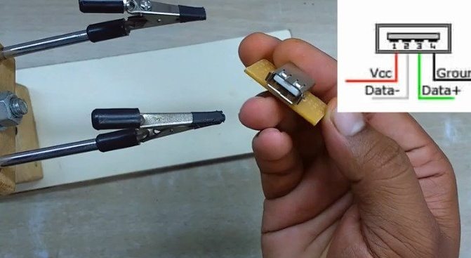
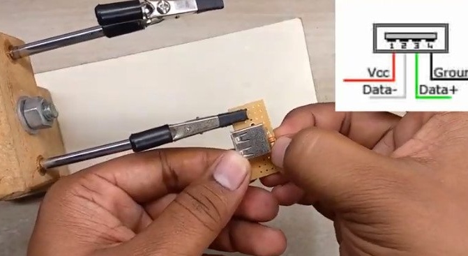
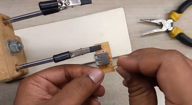
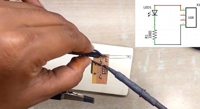
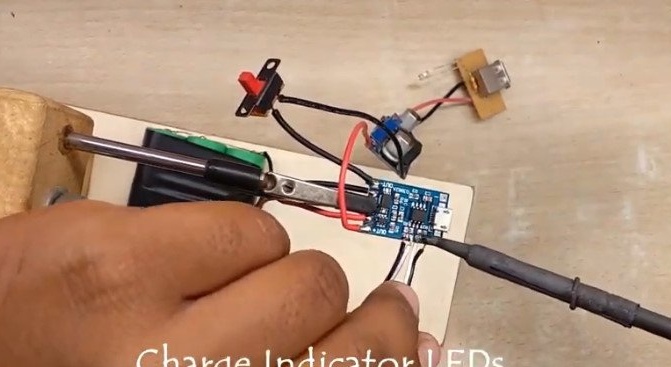
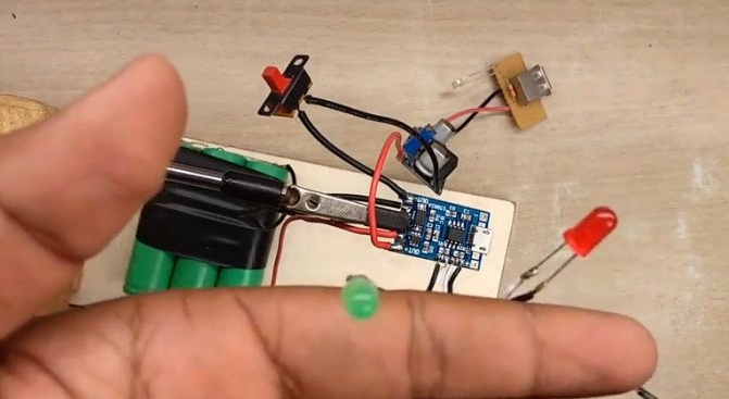
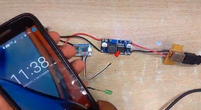
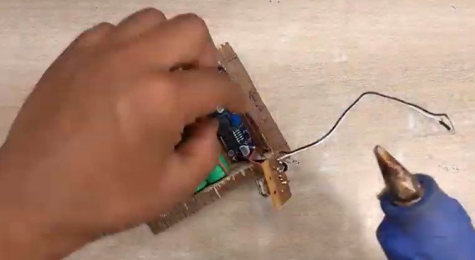
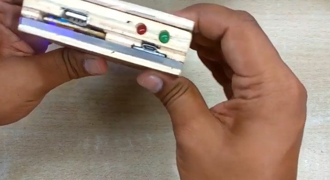
Step Four: USB Output and LEDs
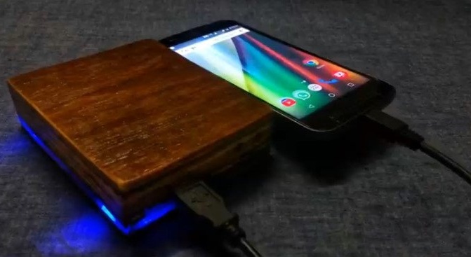
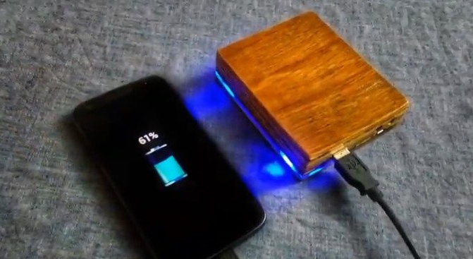
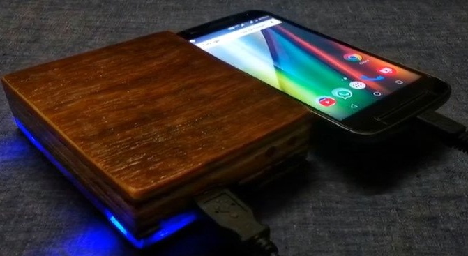
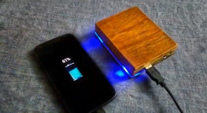
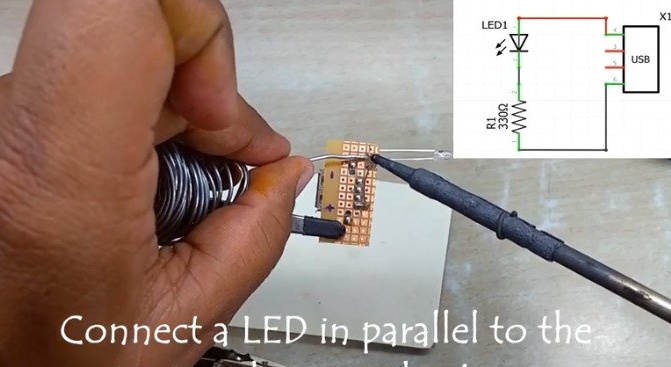
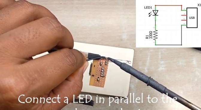
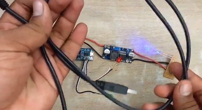
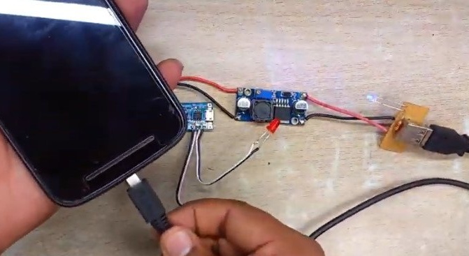
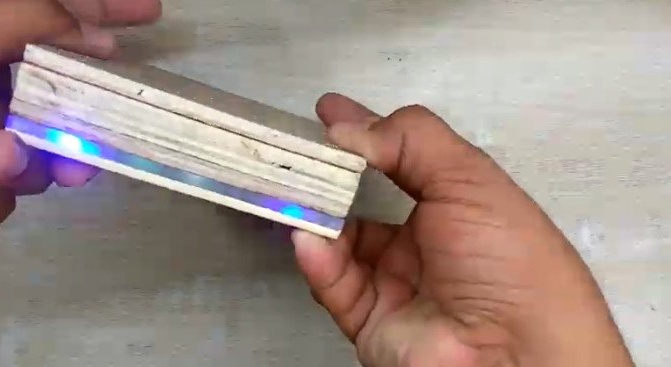
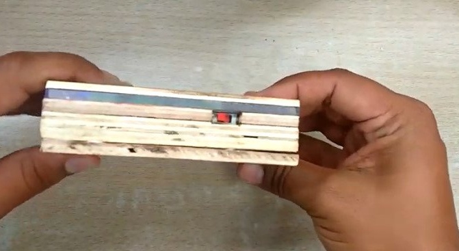
The boost converter output is connected to the USB connector. The diagram shows its pinout. The wizard installs the connector on the board. The master soldered the wires from the output of the board to the connector pins.Parallel to the input, two blue LEDs were soldered. From the charging board, the master soldered the standard LEDs and in their place soldered the blue and red LEDs on the long wires. After installation, the wizard connects the phone to the USB output and checks the operation of the circuit.
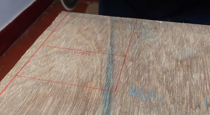
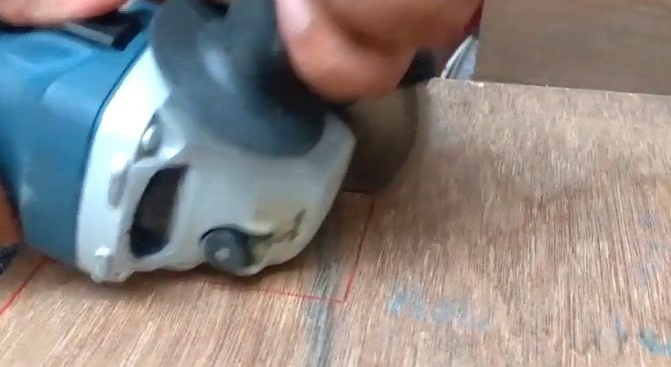
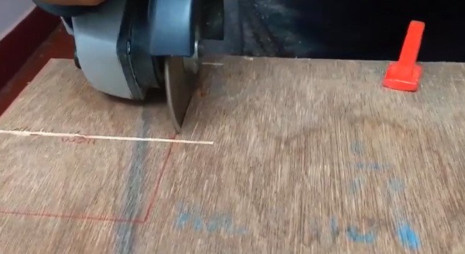
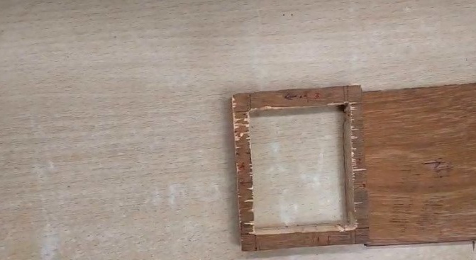
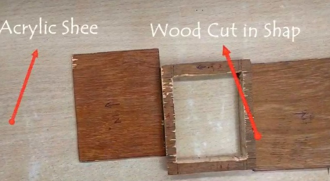
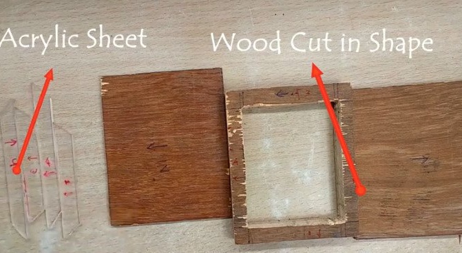
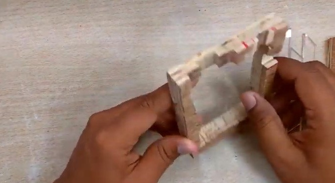
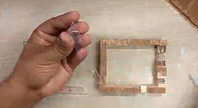
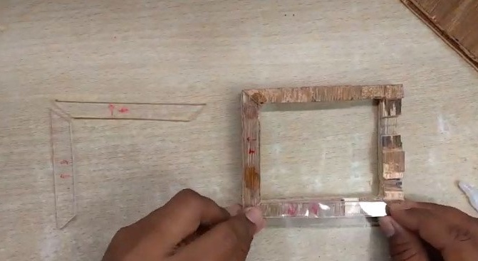
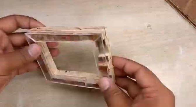
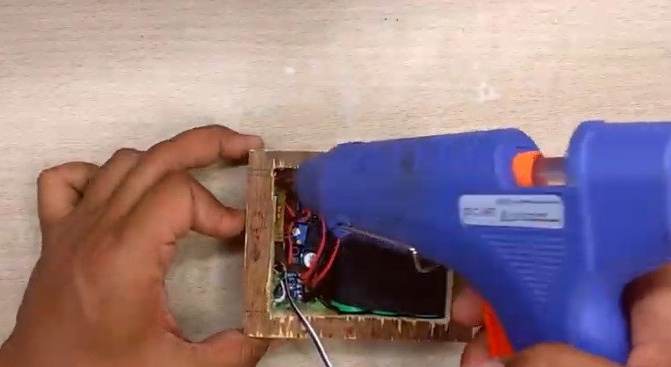
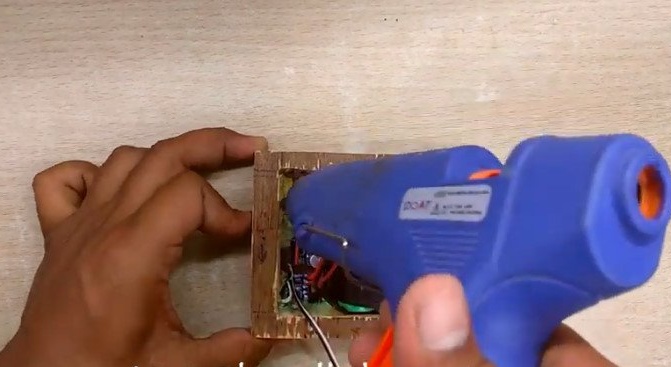
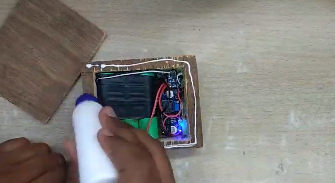
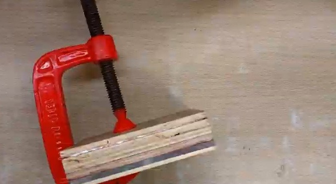
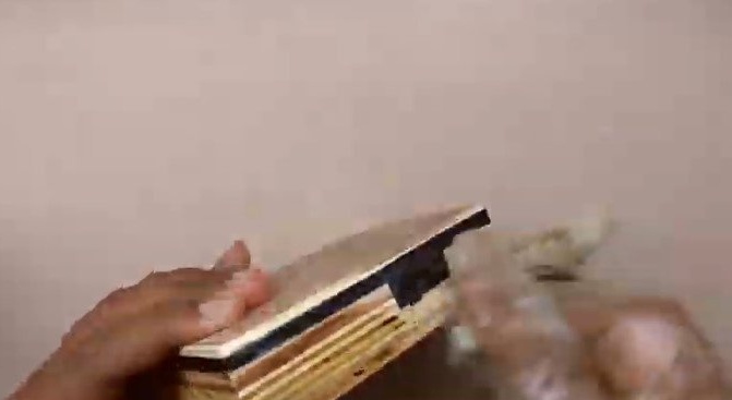
Step Five: Case
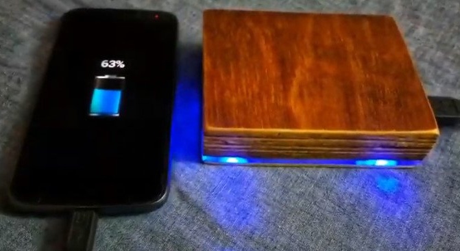
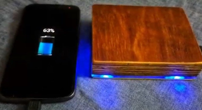
The body was made by a master from plywood. Two covers and a middle part. In the middle part, the master cut out the middle and made holes for electronic components. I glued the lid of plywood. Then I glued the acrylic inserts. Secured the electronic components and glued the second cover. Case size 11 * 9.5cm.
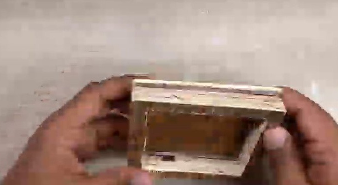
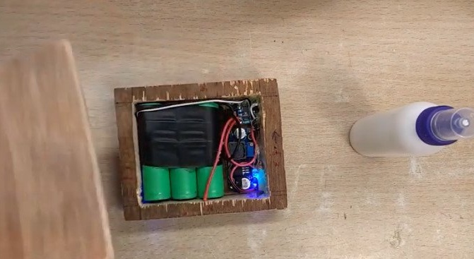
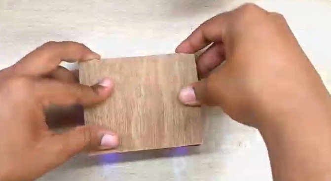
It remains to polish the body and varnish.
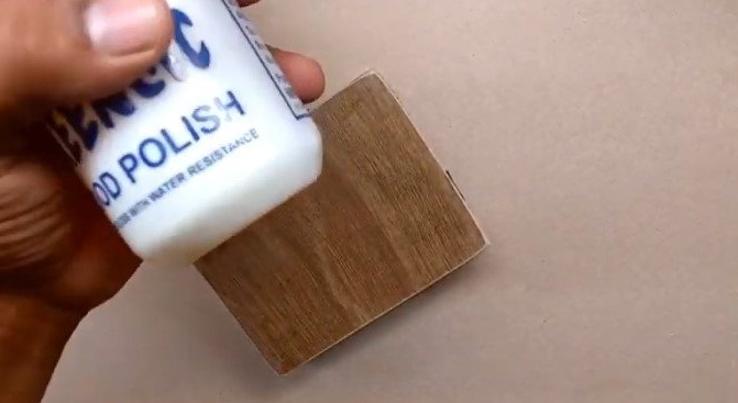
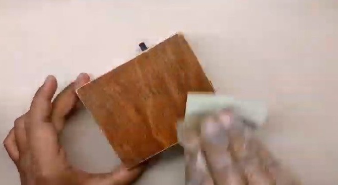
The external battery is ready.