
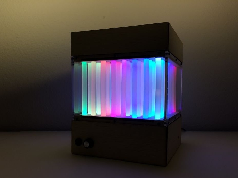
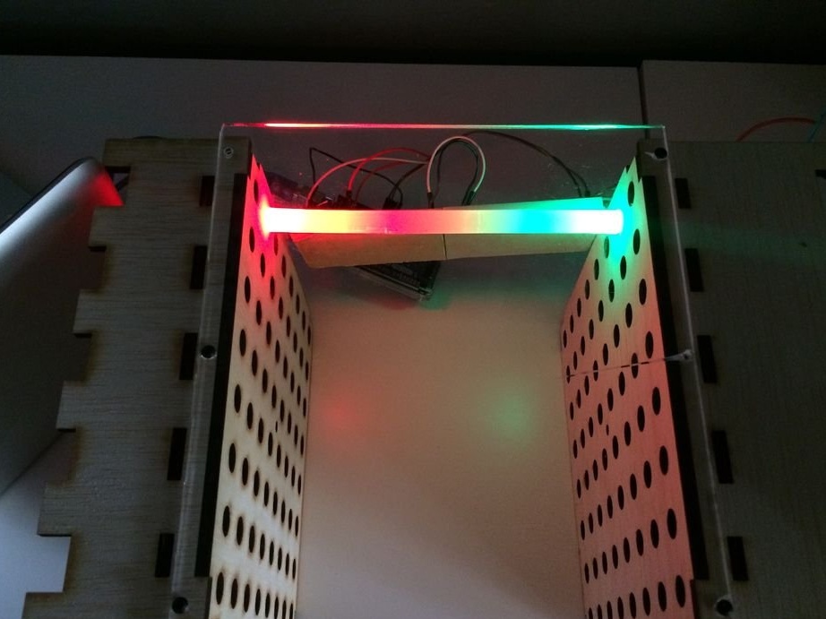
These are two completely two-dimensional arrays of RGB LEDs, directed from above and below into the glue sticks. Therefore, although the design itself is voluminous, it is impossible to show a voluminous pattern with its help. But the LEDs are required less, and entertainment turns out even more. You will see this for yourself by repeating homemade Author Instructables nicknamed jbumstead. By the way, turn it off for now. And turn on the light in the room:
Are you ready? Fast forward to a time machine at that moment when the master only laid out the parts and components of the device:
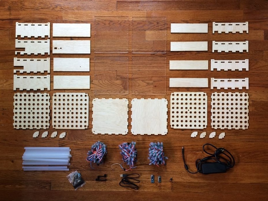
The master took the RGB LEDs from the address tape on the WS2801 or WS2811 chips. He cut the ribbon, and regrouped the pixels into two 8x8 matrices each. Thus, 128 LEDs were used for two matrices.
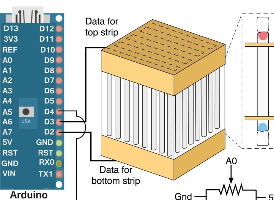
The electrical circuit of the homemade product is shown below, the dashed line on it shows the procedure for connecting the address LEDs to each other (odd rows in one direction, even in the other):
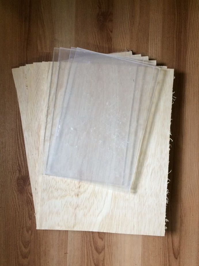
Details of wood and plexiglass jbumstead designs in Fusion 360 and receives laser cutting, then all the necessary files for this are attached:,,,,,,,,,,.
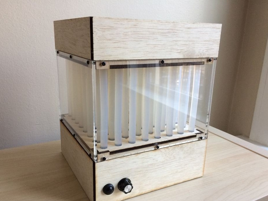
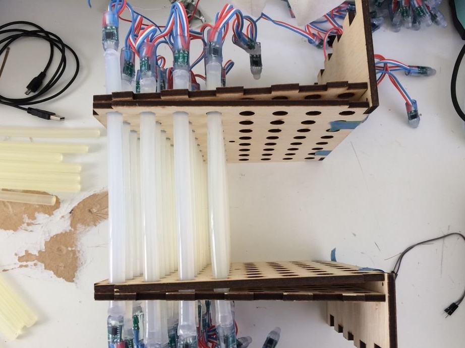
For the sample, he partially collects the body and highlights one core of hot-melt adhesive from each of the ends:
He liked the result, and the work began to boil:
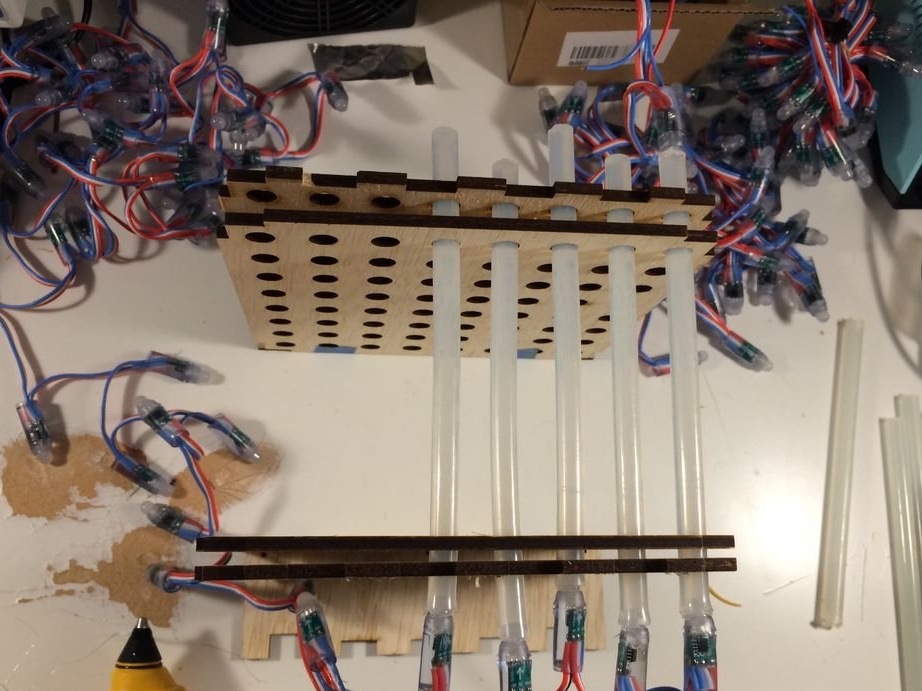
More and more rods:
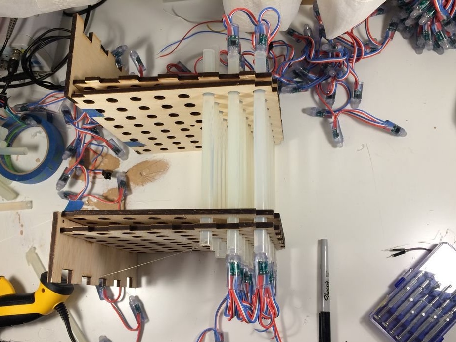
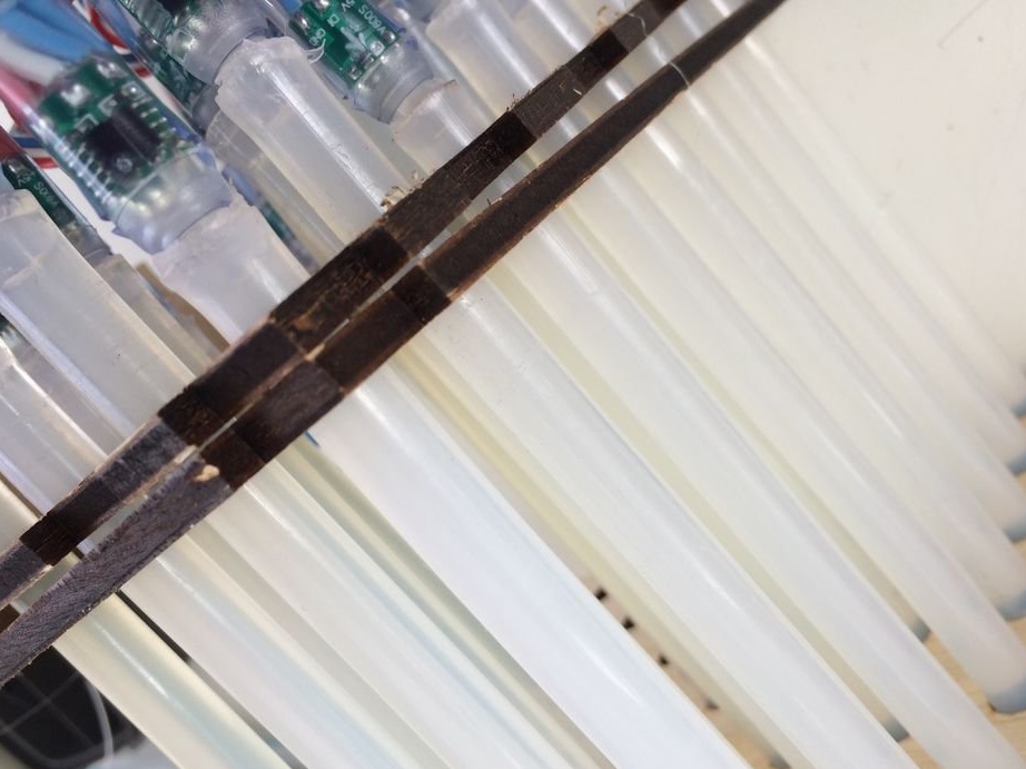
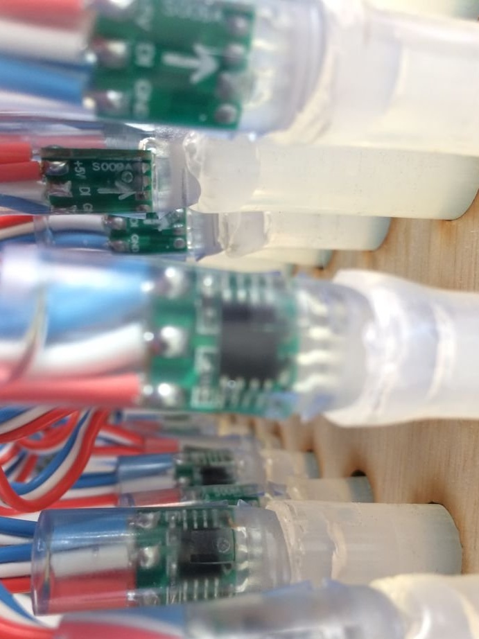
And all with pieces of addressable LED strip, in each of which - on a microcircuit and an LED, we'll take a closer look:
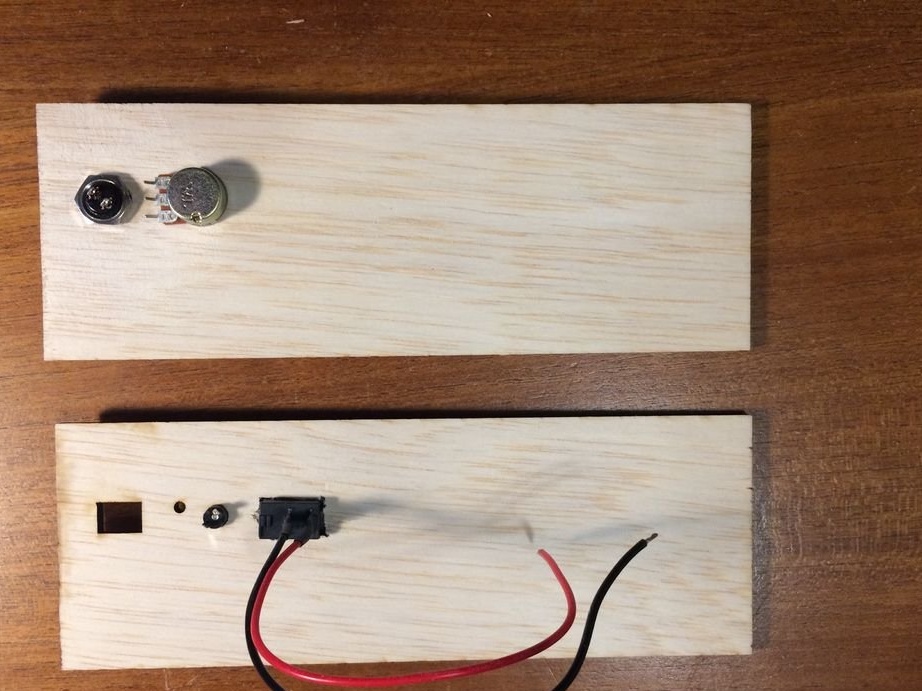
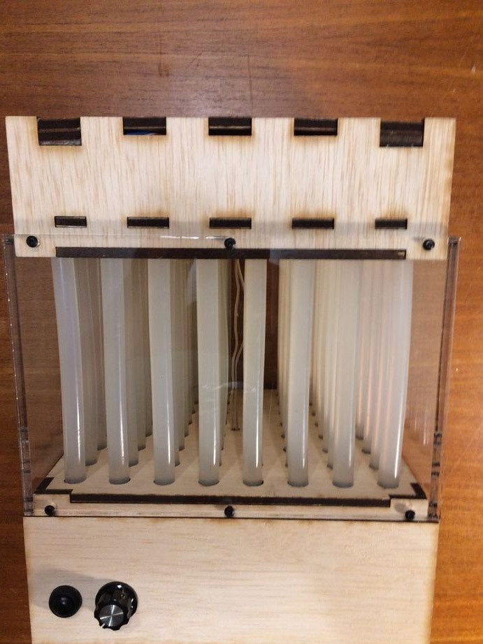
The master puts a button and a variable resistor on the front wall, on the back - a socket and a power switch:
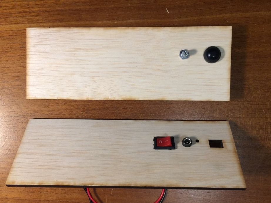
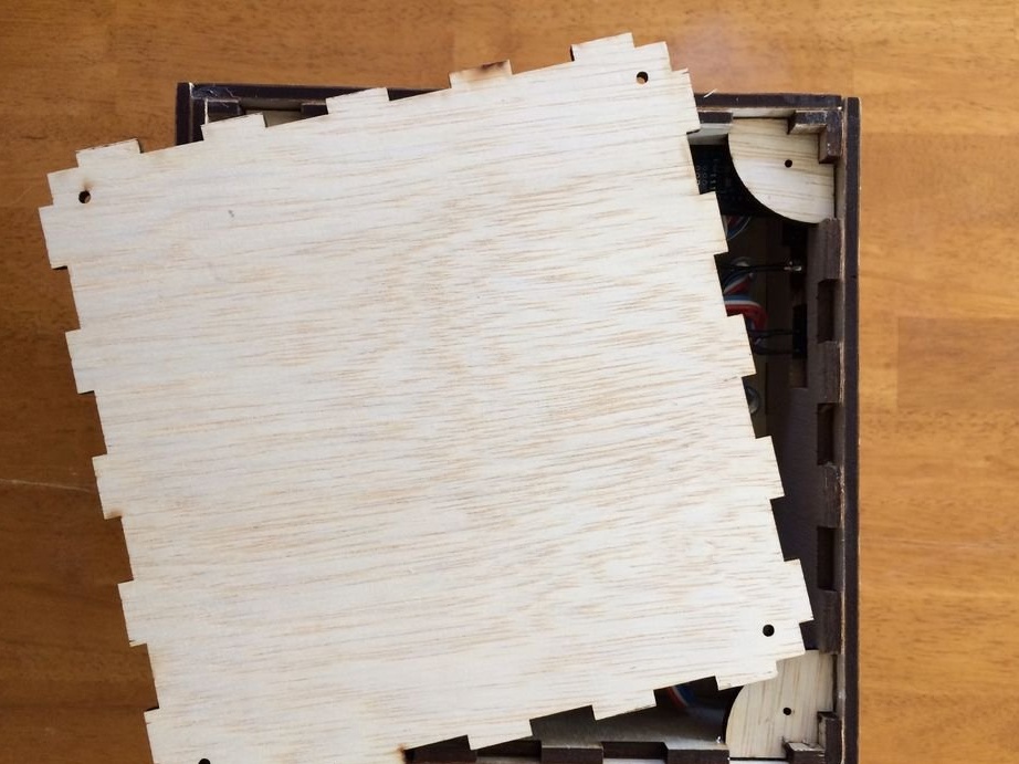
Same thing on the back:
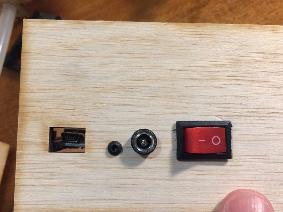
An additional hole on the rear wall is for a USB socket ArduinoTo upload firmware:
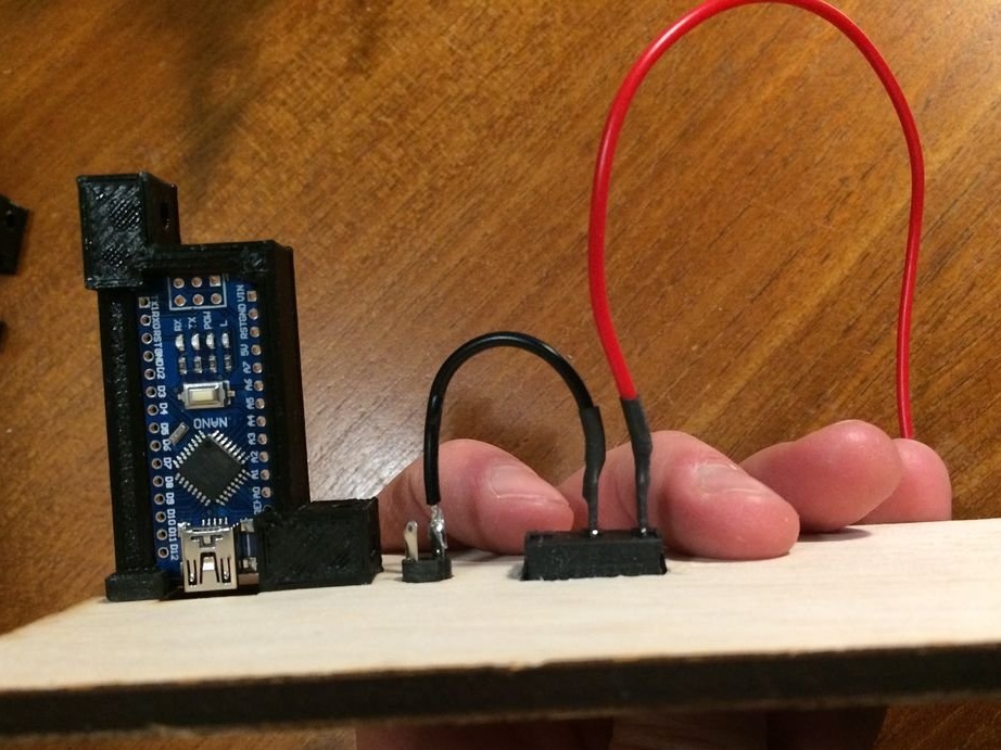
Arduino is in the 3D print holder (supplied):
There are so many grooves in the body parts that everything was able to be assembled without hardware and glue:
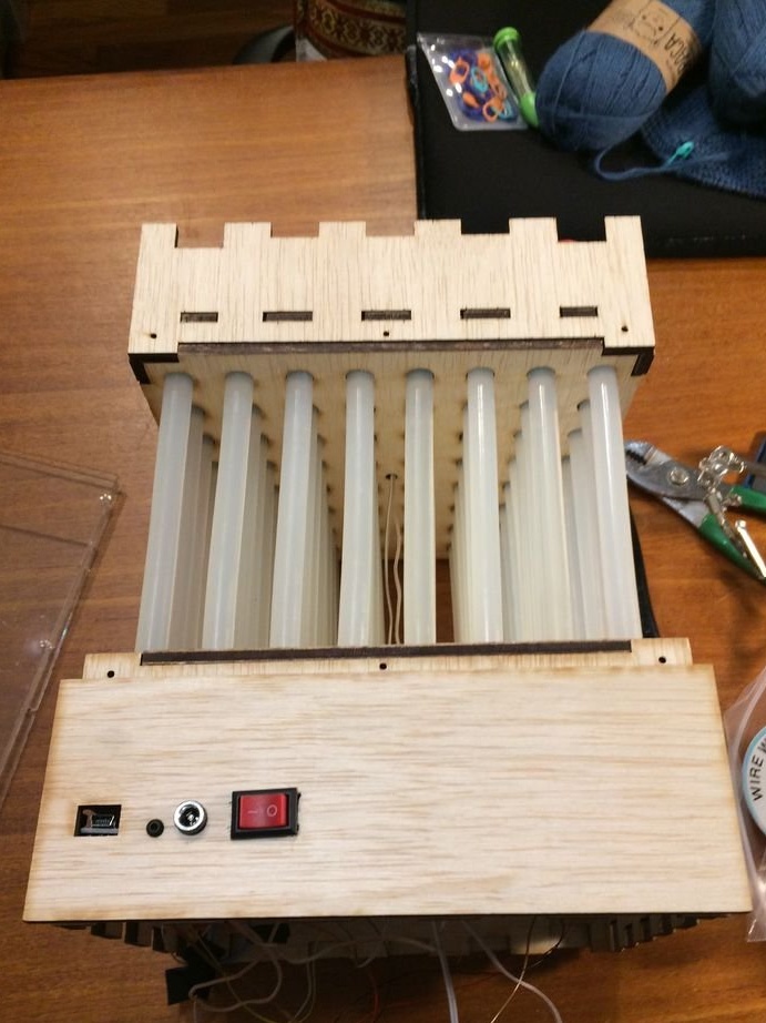
In addition to plexiglass walls, which had to be fixed with M6 screws:
And the top cover, for fixing which self-tapping screws required corners:
The following inputs and outputs were selected on Arduino for various purposes: D2 - data output to tape 1, D3 - data output to tape 2, D4 - data input from a button, A0 - data input from a variable resistor. uses the library. Using the button you can select the effect, and with a variable resistor - adjust the speed of its display.
This homemade product, like a cardboard box pasted with veneer, an article about which I also recently translated, participates in Instructables in the Fake-Real contest. The theme of the contest is to imitate anything with the help of anything else.