
Greetings the inhabitants of our site!
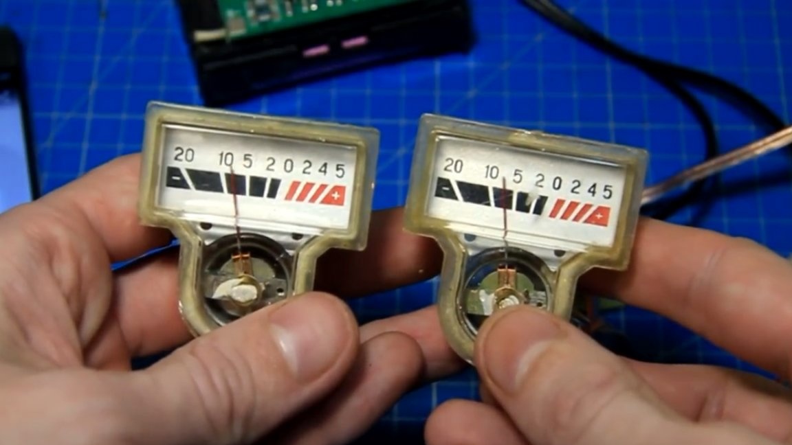
For quite some time now, the author of YouTube channel “Radio-Lab” has these old arrow indicators from some old tape recorder in a box.
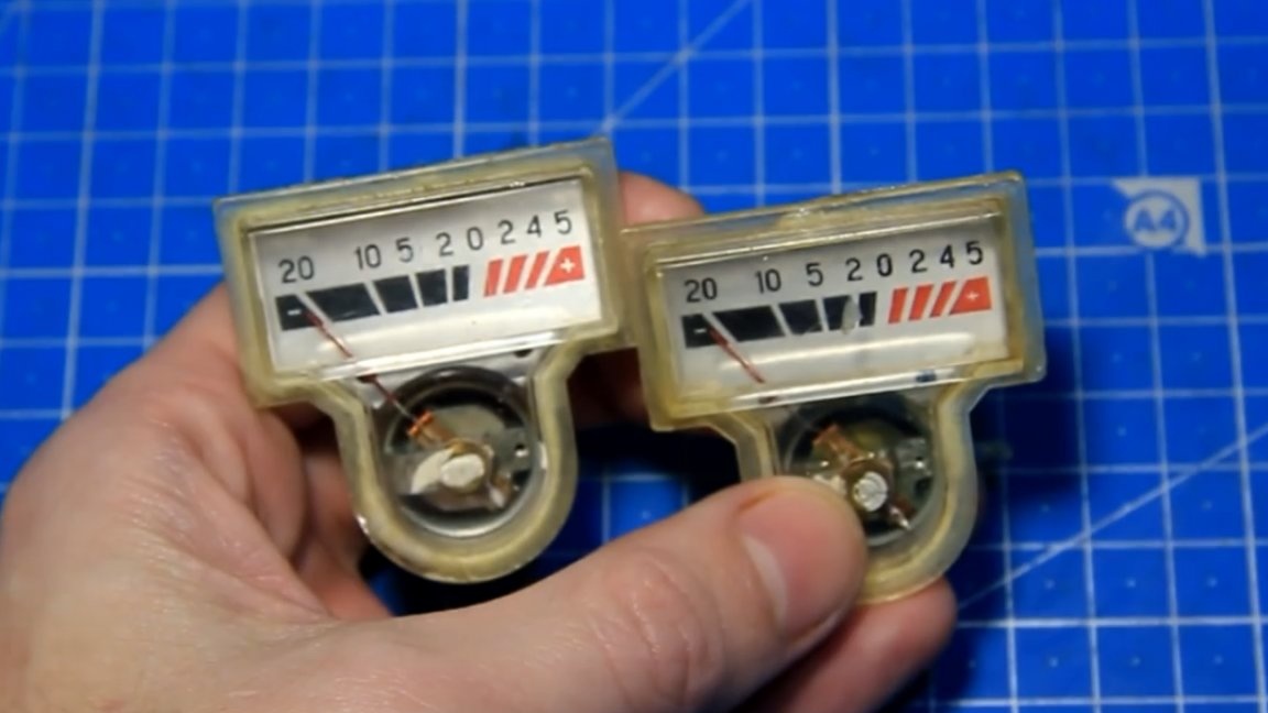
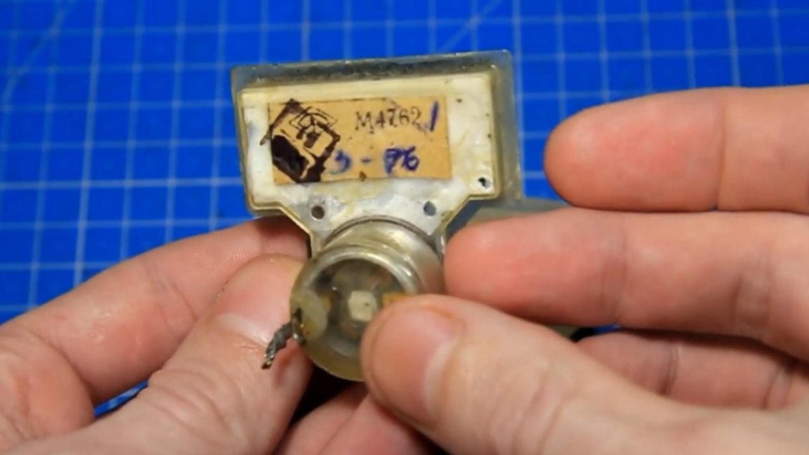
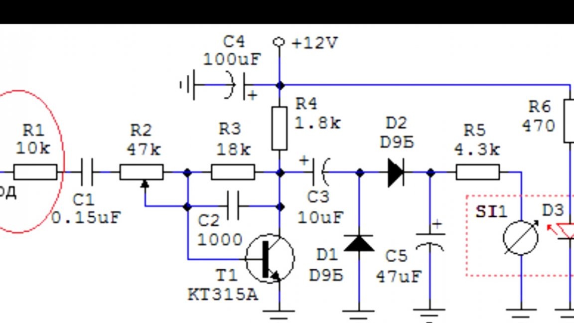
In this case, this model indicators m4762. In audio technology, dial gauges are often used to visually control the level of an audio signal. Also, such indicators in the work look vintage and unusual, because the author decided to try to connect these arrow indicators and look at the work of the arrow. But it is undesirable to connect such indicators directly to the amplifier, since they can be damaged. For the shooters to work properly, an additional board is needed, which will control these arrows. On the Internet, such a scheme was found for controlling dial indicators.
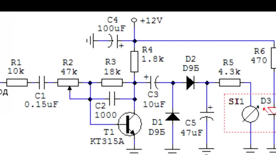
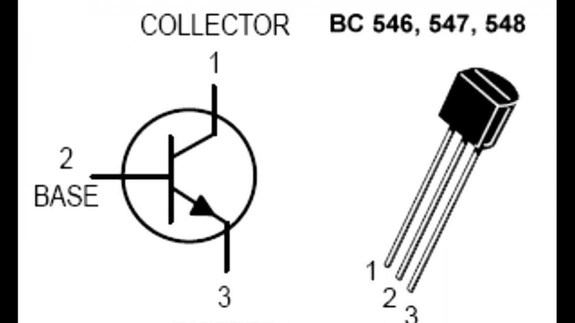
The scheme is very simple and in order to try it should be enough. And most importantly, it is easy to repeat, especially for beginner hams. Instead of the CT315 transistor, the author bought a more modern analogue of the bc547.
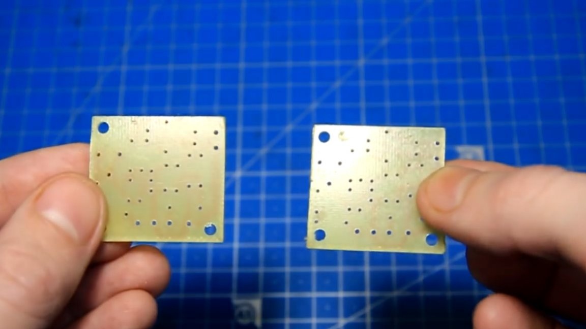
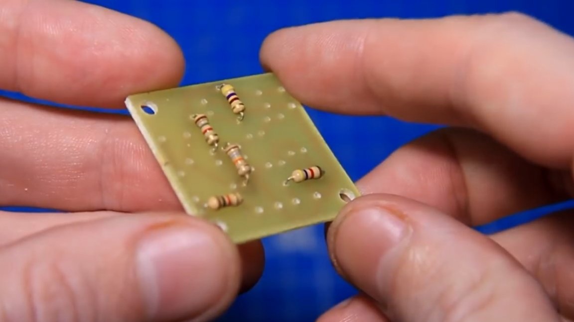
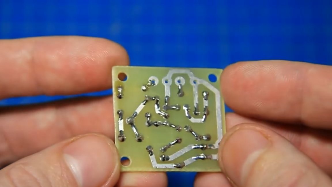
Further, according to the scheme, the author drew such a printed circuit board:
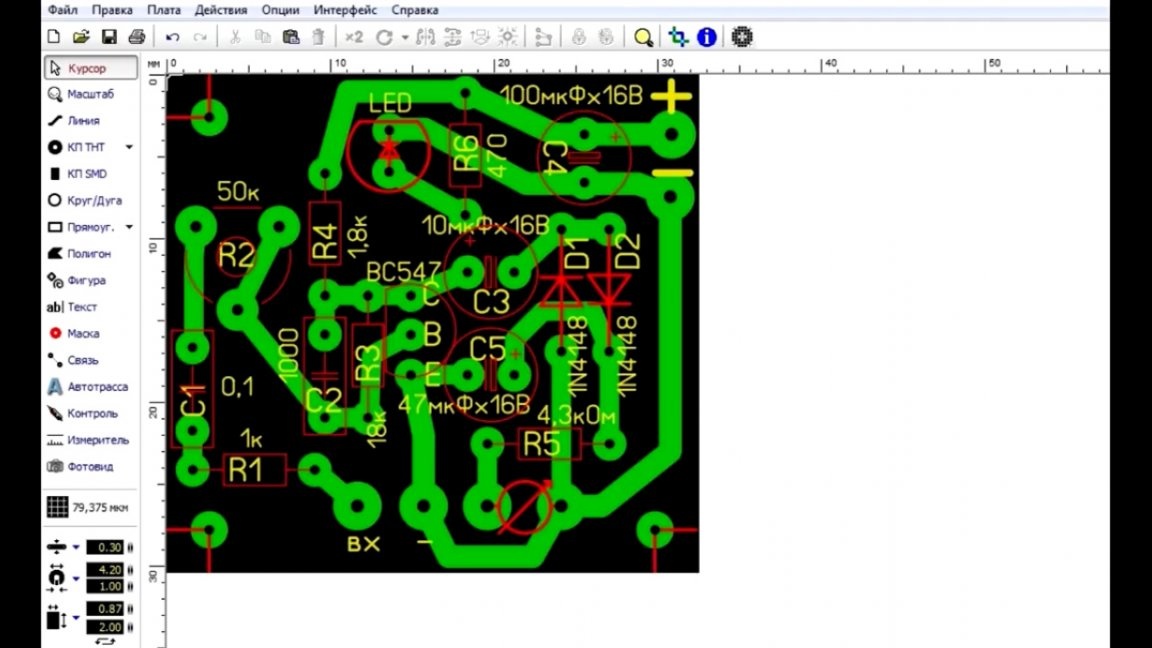
Here we have such a board. She's not big. For each indicator, such a board needs its own.
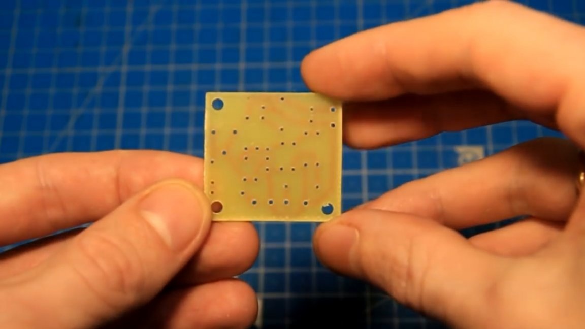
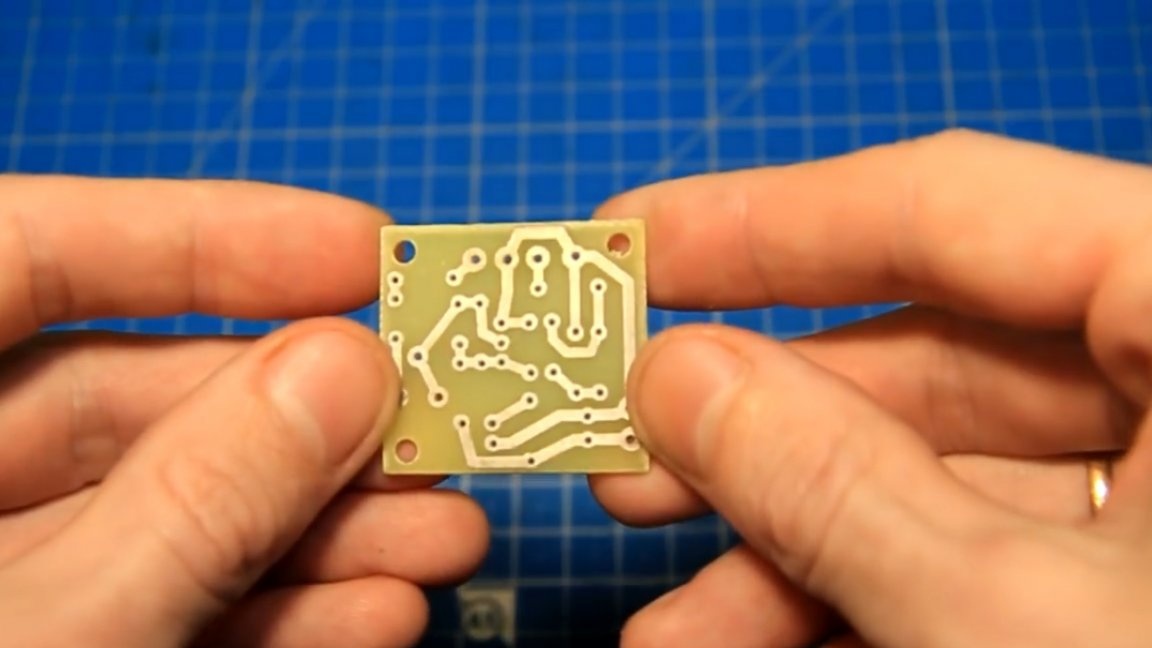
The author made 2 such boards for the left and right channels, respectively.
At the nearest radio market, all the necessary spare parts were bought.
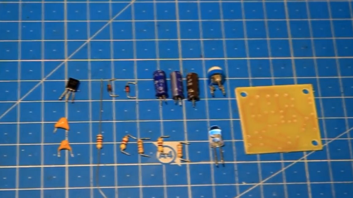
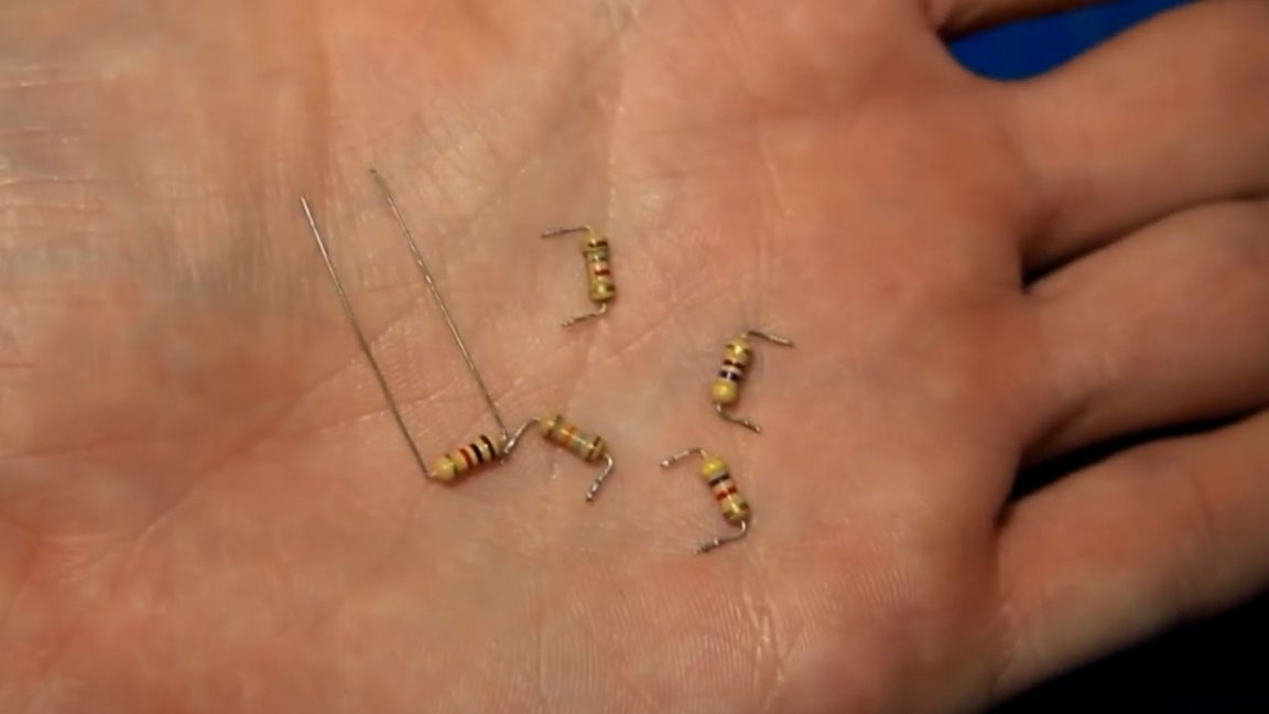
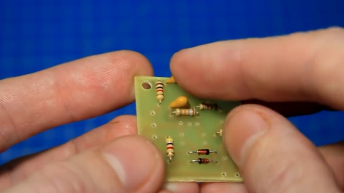
So, let's get down to the build itself. As usual, we first solder the fixed resistors.
In order to find out the values of the resistors, it is convenient to use such a tester of radio components.
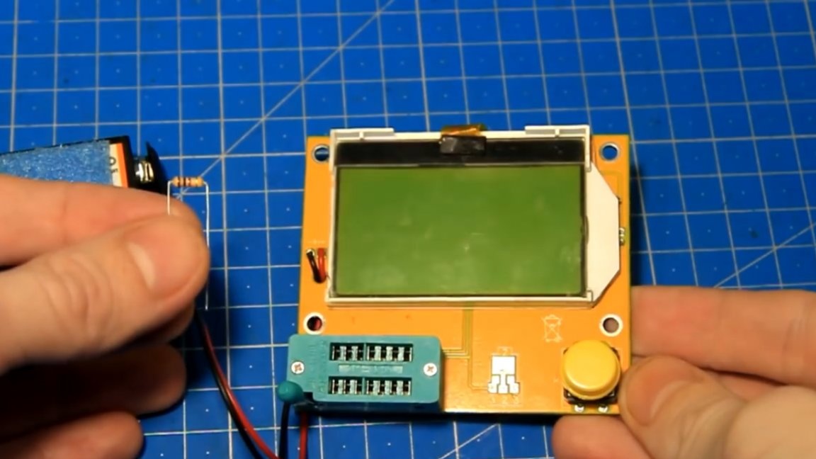
By measurement, the value of this resistor is 1 kOhm.
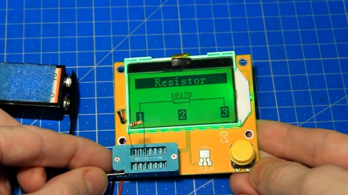
We install it in its place. According to the scheme, there are 10 kOhm, but the author took a smaller resistor so that the sensitivity of the board was higher.
We solder the resistor in its place, and then similarly all the others.
Then, observing the polarity, install the diodes.
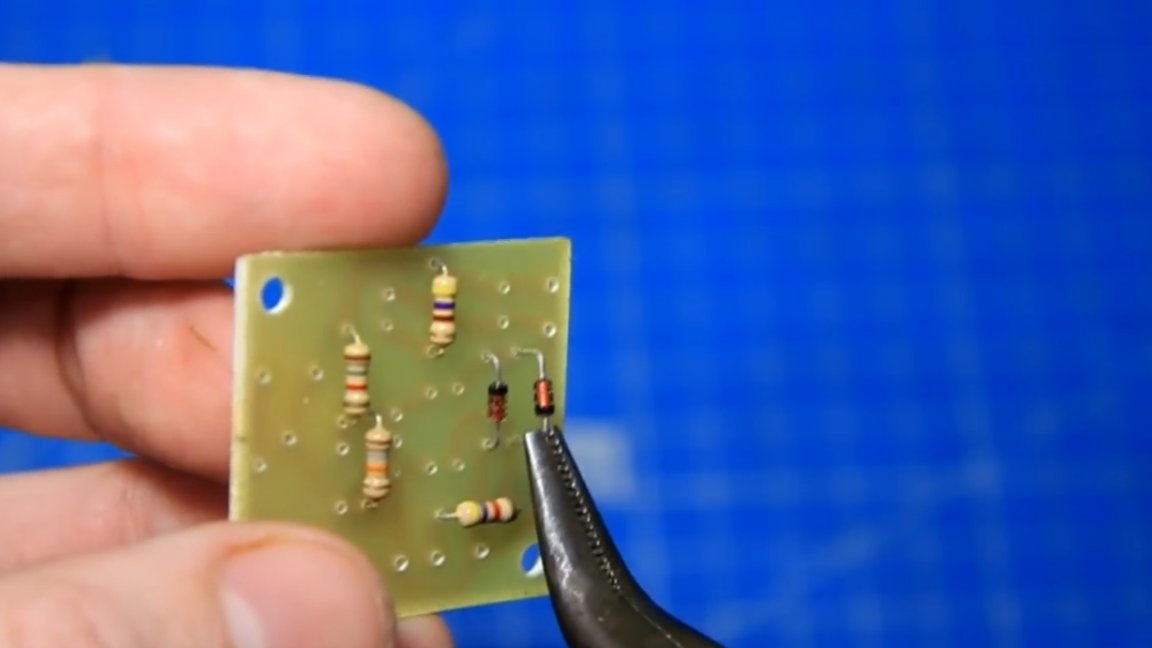
Next, we install these capacitors.
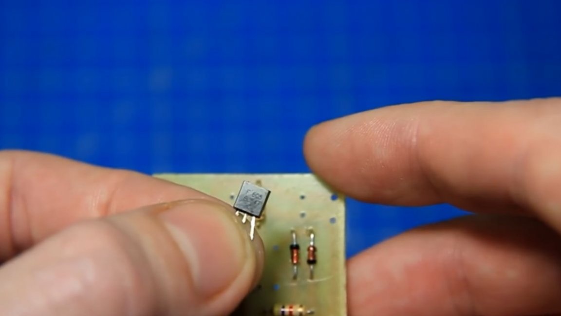
Then, be sure to observe the orientation, install the transistor.
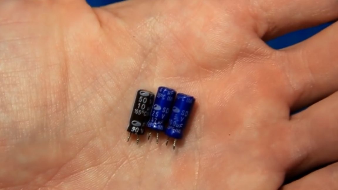
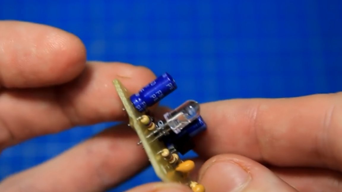
Further, observing the polarity and ratings, we install electrolytic capacitors.
Also observing the polarity, install the LED.
And we have the last detail left - this is a tuning resistor of 50 kOhm. It is needed for the ability to adjust the sensitivity of the board.

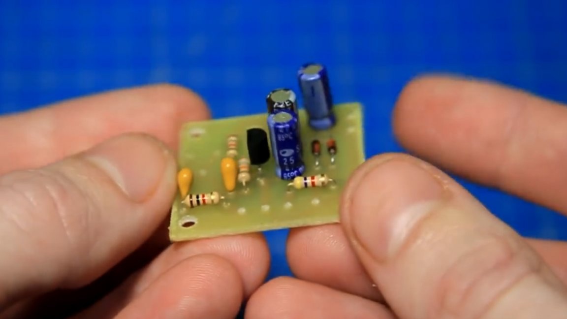
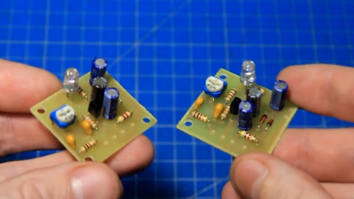
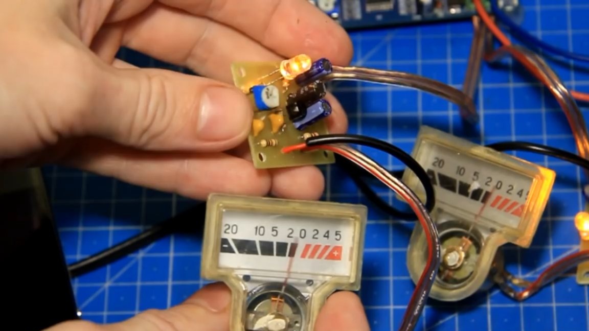
Well, that’s all. The assembly work is finished and the finished board looks like this, there is nothing complicated here.
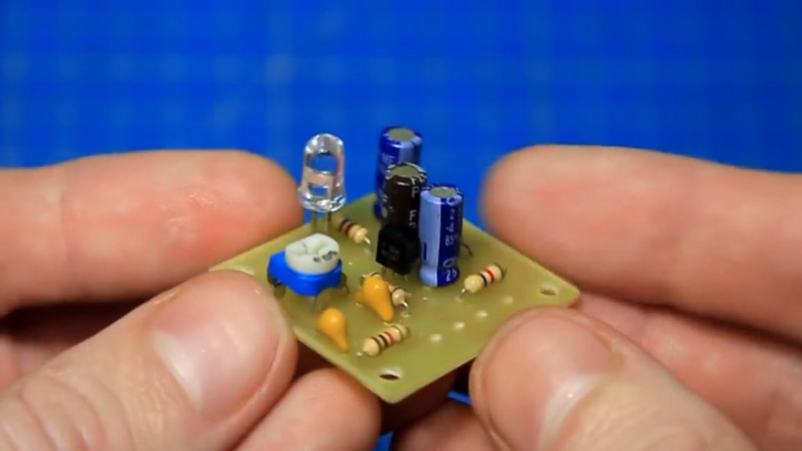
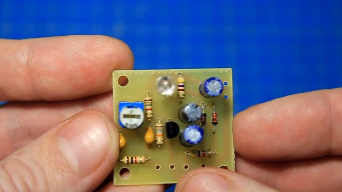
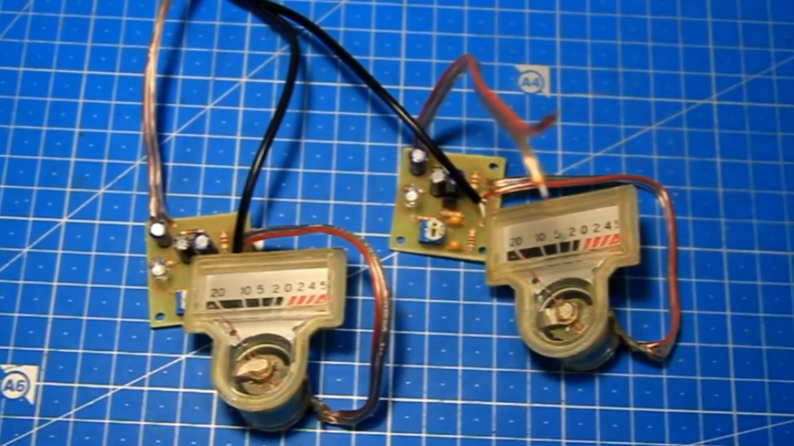
As mentioned earlier, the author made not one such board, but two, separately for the left and right channel.
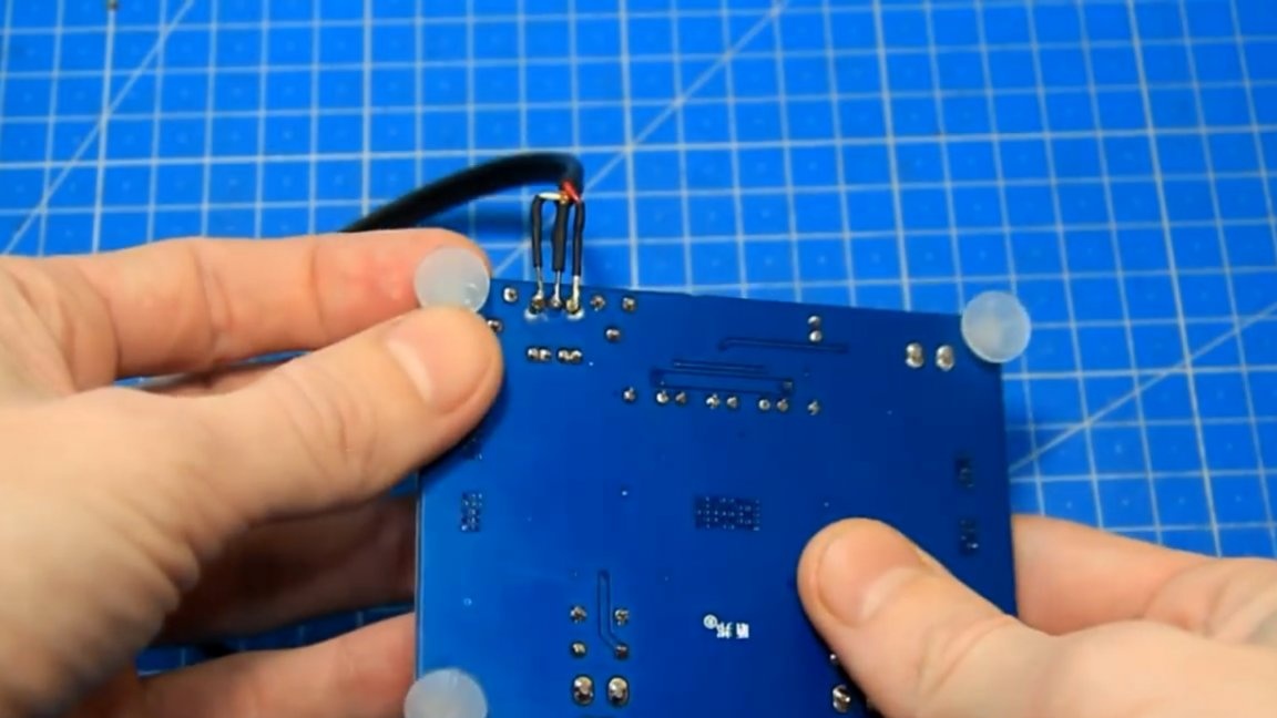
To connect the power and dial indicator, it is necessary to solder the wires to the boards. Wires with red marks, in this case it is a plus (+).
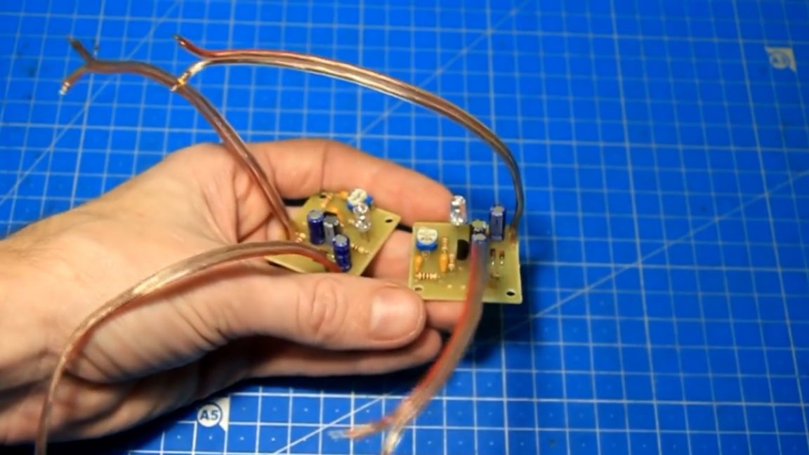
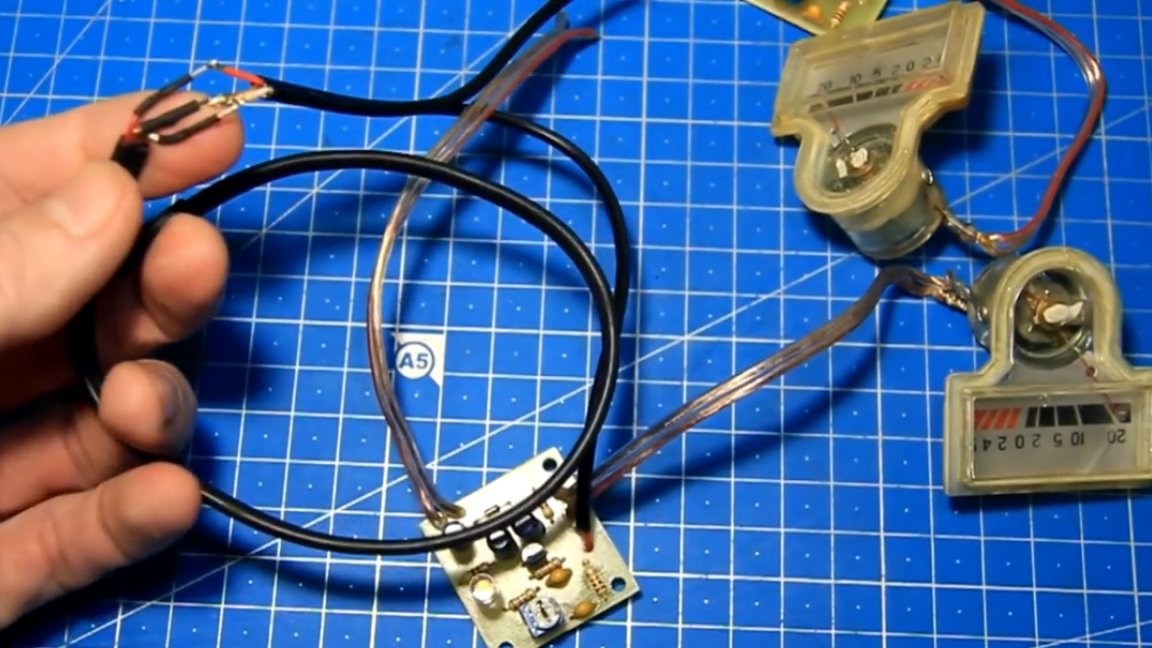
In order to signal, be sure to use shielded wires. This is necessary so that there is no interference to the input of the amplifier, since we will take the signal from the input of the amplifier.
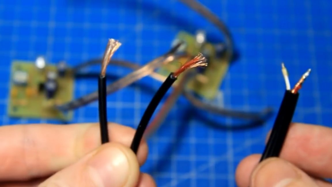
So, soldered the signal wires. A wire braid is a common contact (it's minus (-)).
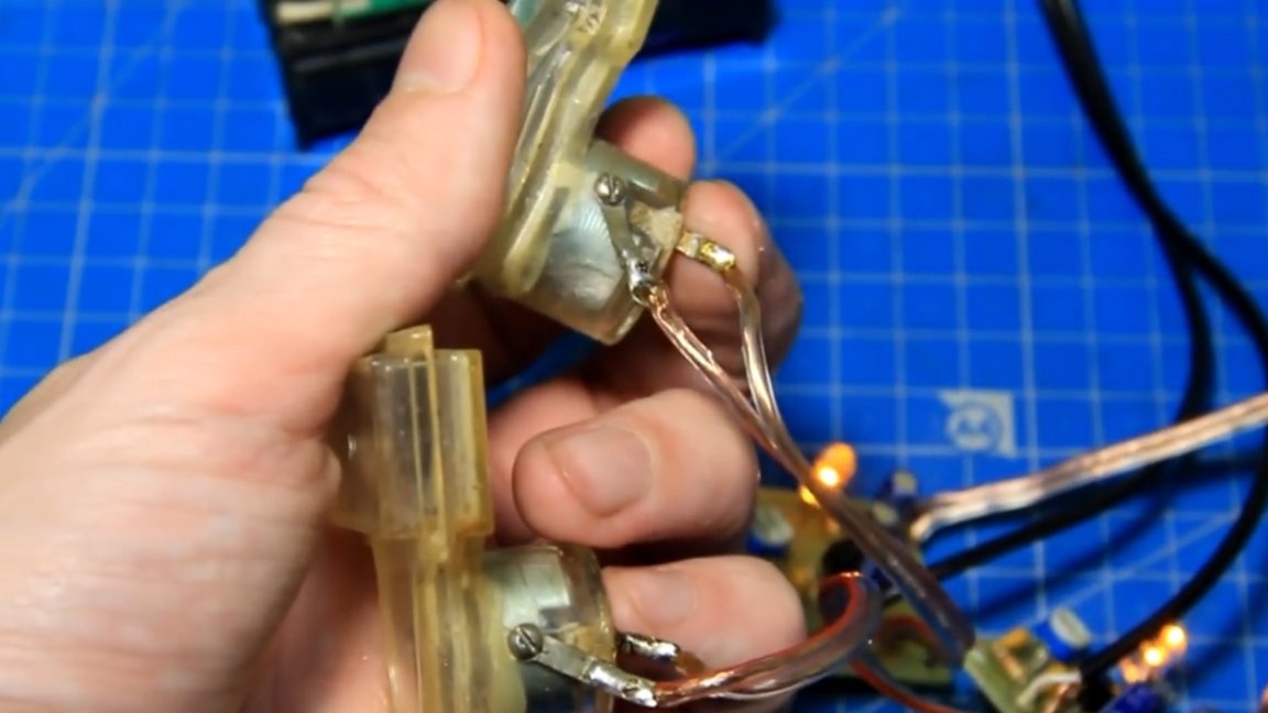
Now you need to solder the output from the handkerchief to the indicator, observing the polarity, otherwise the arrow will move in the opposite direction.
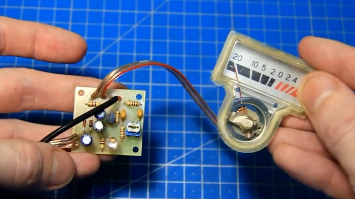
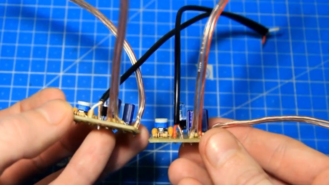
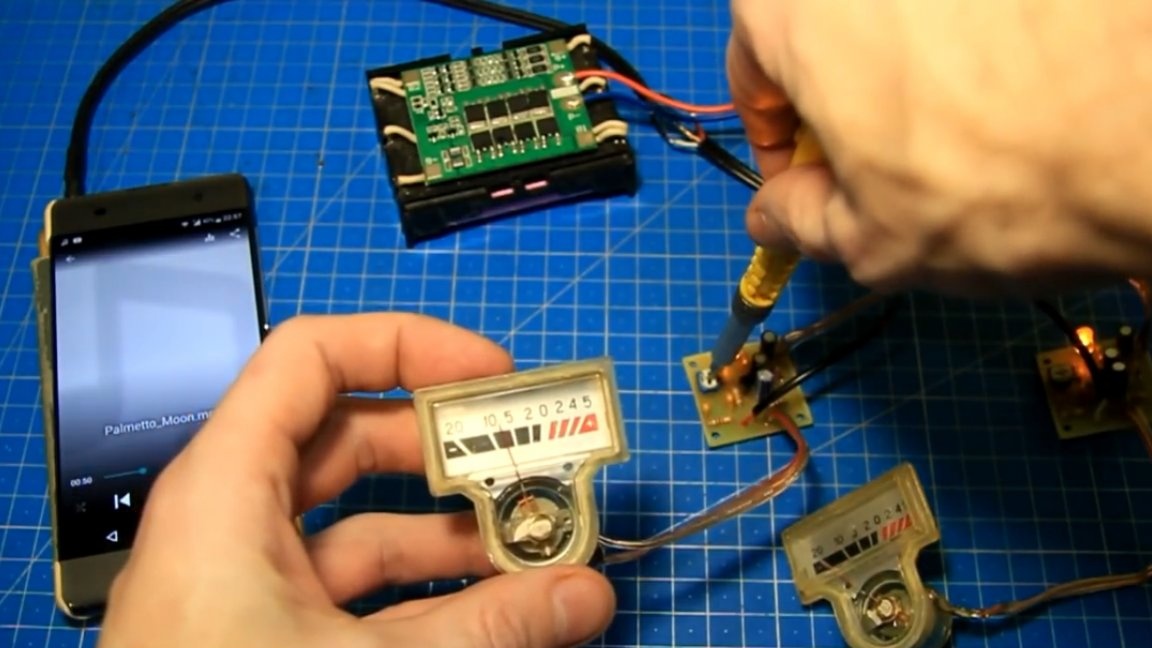
So, we soldered the wires to the indicator, now everything is assembled and there are all the necessary wires for connection. Of course, what is collected is good, but it is much more important to check whether all this will work properly. To give a sound signal, we’ll take such a wire with a 3.5 mm jack and a 12-volt battery, consisting of 3 cans of 18650 lithium-ion batteries.
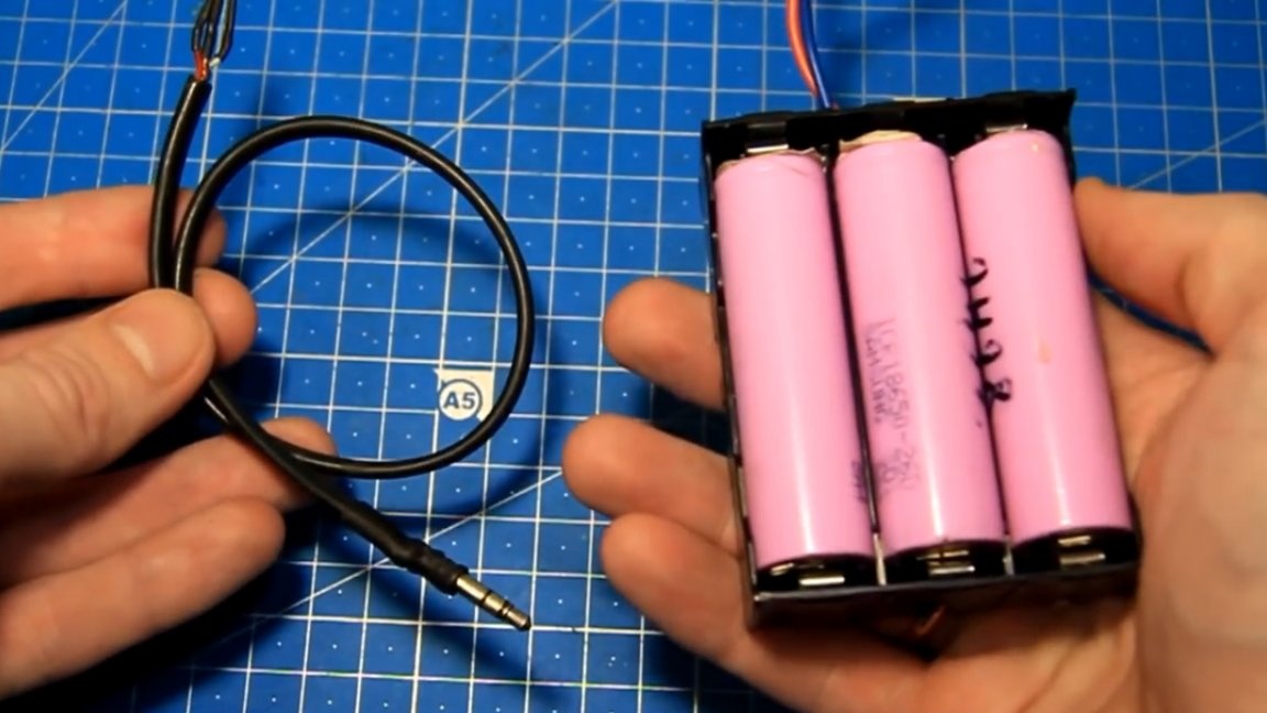
Now solder the wire with the connector to the input wire of the indicator board. Observing the polarity, we supply power to the scarves.
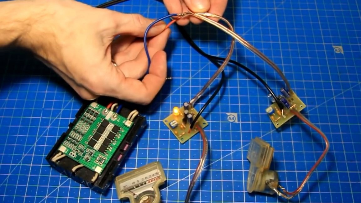
LEDs light up, so the power is coming. We connect the connector to the phone and turn on the test music, but the arrows do not react to the sound signal.
We try to rotate the tuning resistor.
As it turned out, the arrow is moving in the wrong direction. To reverse it is necessary to change the polarity of the wires on the indicator.
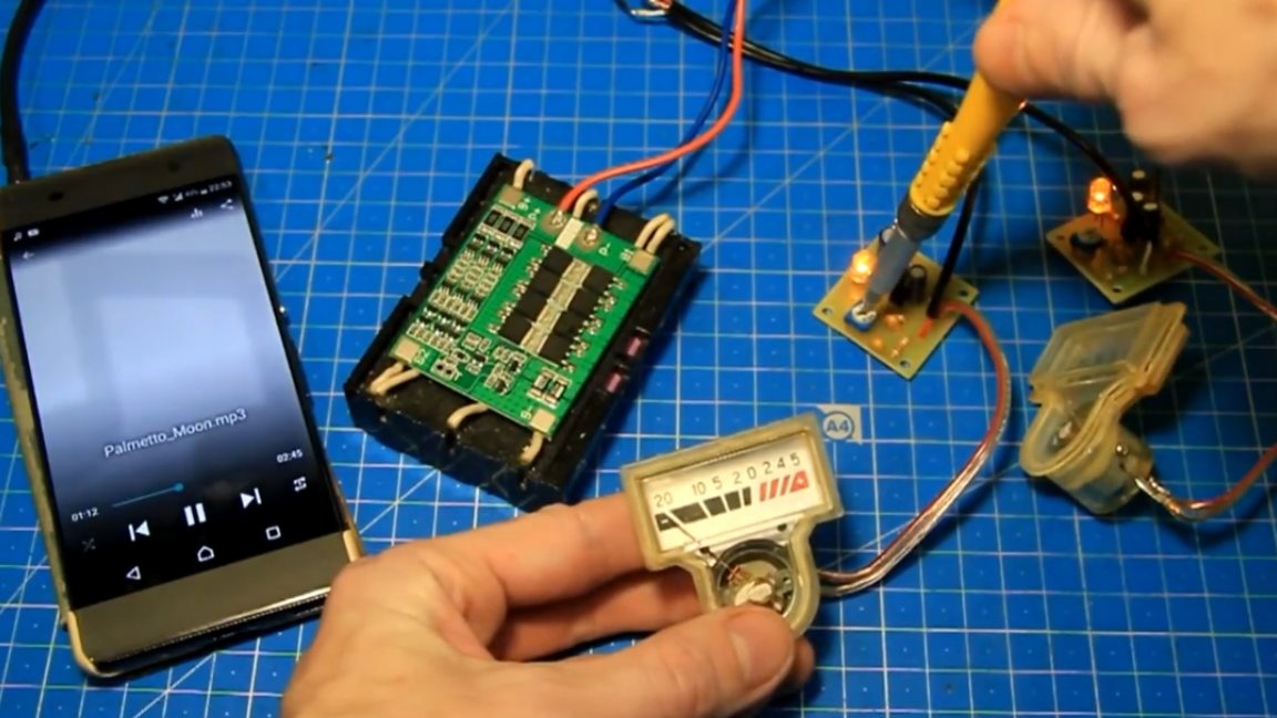
We try with the music again, reduce the resistance of the tuning resistor, and the arrow deviates and starts moving to the beat of the music.
Next, configure the second indicator.
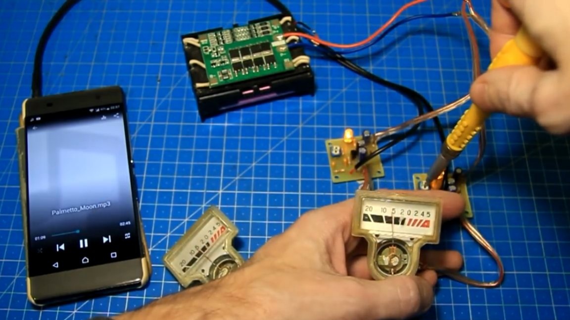
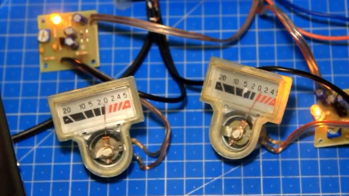
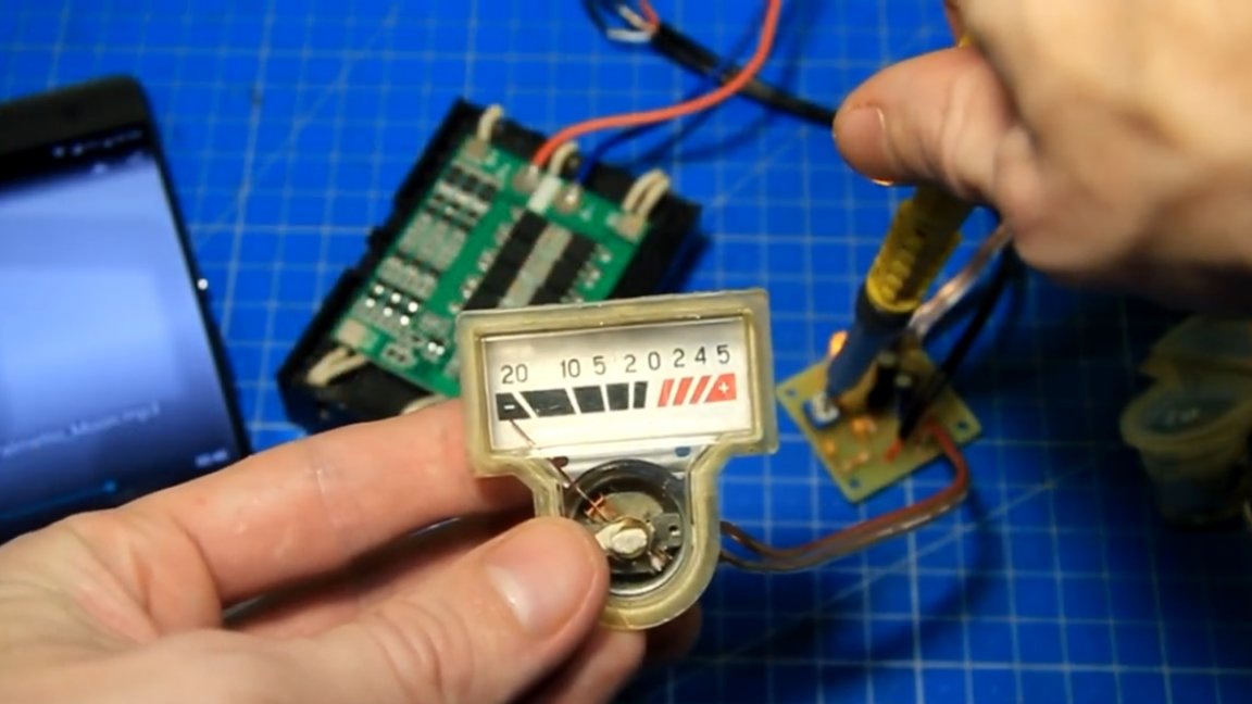
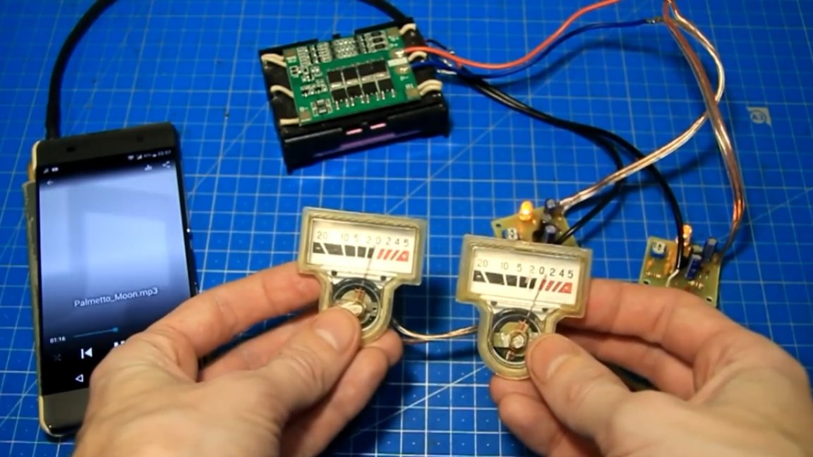
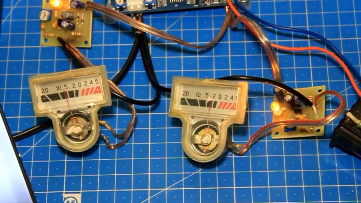
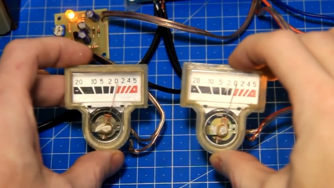
As you can see here, too, everything works fine. Both indicators have earned and this is how it looks:
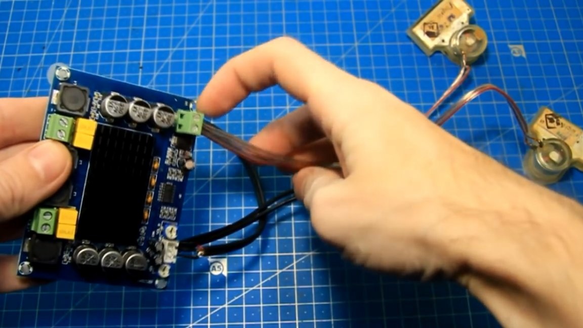
But that’s not all, the author wants to show how it all works together with an amplifier.
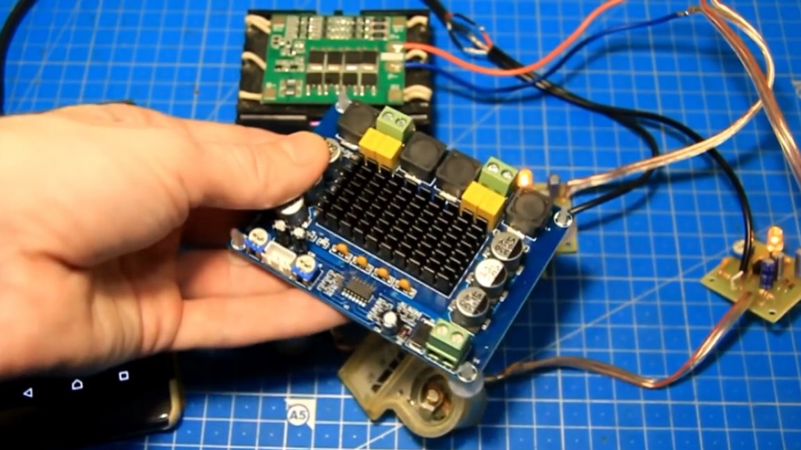
This amplifier is on the TPA3116D2 chip. The author uses this amplifier as an example, the connection is the same for other amplifiers. Below is a connection diagram for one channel, the second is connected in the same way.
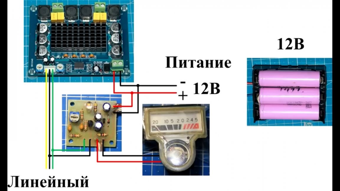
The author soldered a wire with a 3.5 mm connector to the amplifier input and soldered a wire of inputs to the level indicator boards in parallel there.
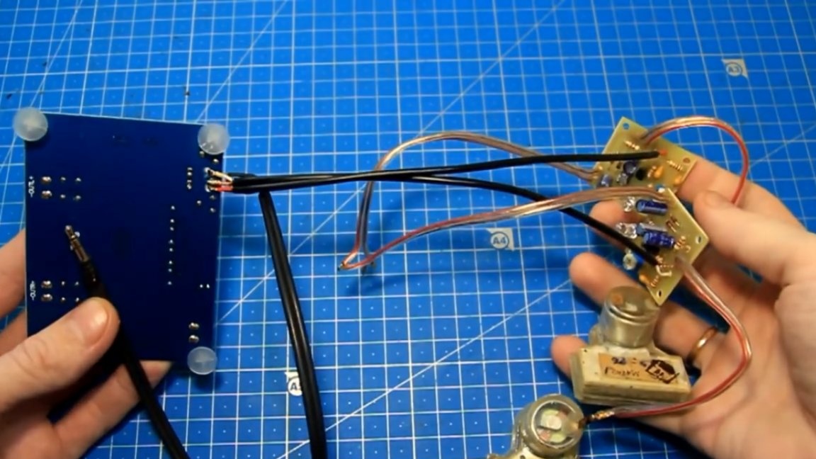
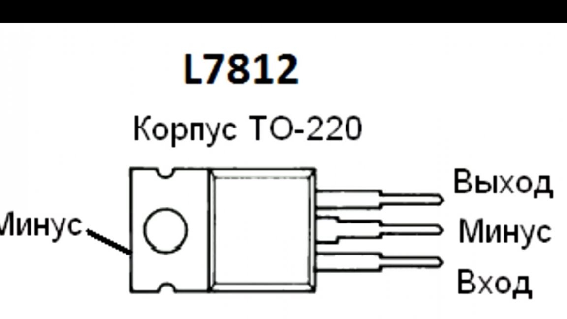
The test power supply of the amplifier is 12V, so the power wires of the indicator boards can be soldered to the power connector of the amplifier. If the amplifier power is higher, then to power the indicator boards it is necessary to use a step-down stabilizer, for example, L7812.
So, everything is connected, you also need to connect the speakers. Powered by a 12V battery. We slightly reduce the gain level on the amplifier board so that it is not very loud for the microphone (the author filmed the whole process on video). We supply power to the amplifier.
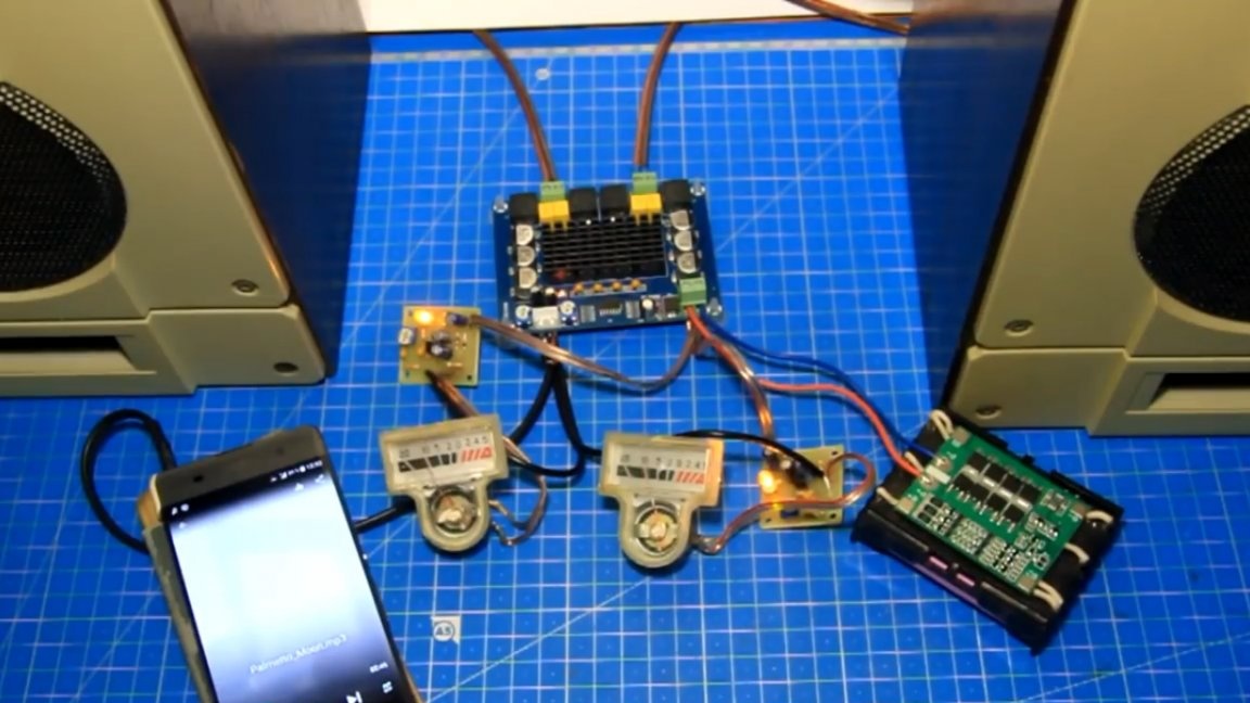
The LEDs on all the boards lit up, there is power everywhere. Now we connect the connector to the phone and turn on the test music. More details in this video:
The gain levels and sensitivity of the indicator must be adjusted individually. Also, this board can be connected to the output of the amplifier, but then the resistor R1 must be taken in the range from 220 to 470 kOhm to reduce the sensitivity of the indicators and there was a normal course of the arrows.
Well, in general, as we saw, everything works and the arrows move. This indicator board is the simplest, and as a measuring device, it is still not worth using it, especially without fine-tuning. But as a test project and visual aid, this is all worthy. Such a dial indicator is easy to assemble and with its help you can give your product an unusual look for inexpensive and simple and add vintage arrow indicators to it. Everything works with other types of indicators. Of course there are better projects, but they are more complicated and more expensive. The task was to make it easy and cheap to assemble a product that worked immediately. Try and repeat.The drawing of the board and other links will be in the description under the original video of the author (link SOURCE at the end of the article).
And that’s all. Thank you for attention. See you soon!