
To supply various transistor and microcircuit designs, different voltages are required: 1.5V, 3V, 4.5V; 9B; 12V To do this, I assembled a power supply with an adjustable output voltage from 0.5V to 15V. Moreover, this voltage will remain stable not only when the mains voltage changes, but also when the load current changes from a few milliamps to 0.5A. In addition, the power supply is not afraid of short circuits in the load circuit, which are not uncommon in the practice of ham radio. And now more about the operation of this unit, a diagram of which is shown in the photo
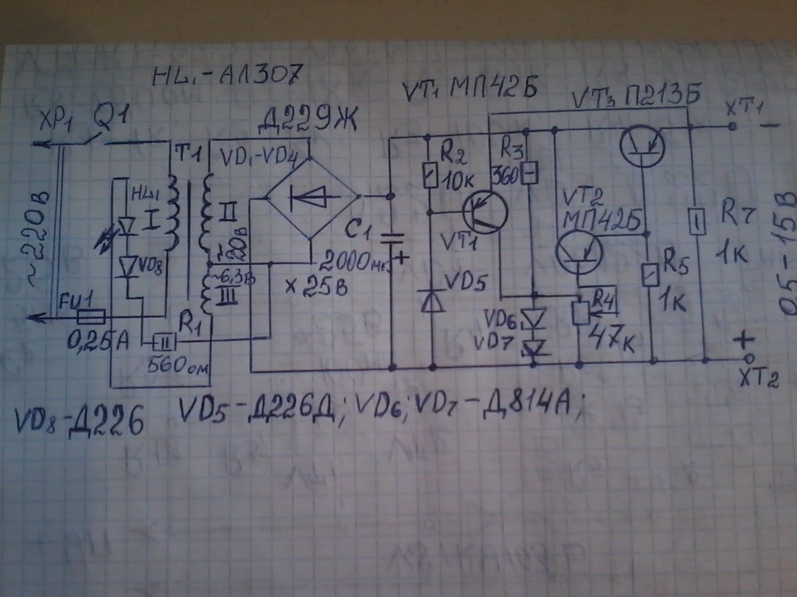
It turns on using the XP1 plug. When the contacts of switch Q1 are closed, the mains voltage is supplied through the fuse FU1 to the primary winding of the step-down transformer T1. The presence of mains voltage on the transformer is indicated by a light indicator - an LED connected to the 3rd winding of the transformer. At the output of the secondary winding, an alternating voltage of 20v appears. It is rectified by diodes VD1-VD4, connected by a bridge circuit.
A large capacity oxide capacitor C1 is installed at the output of the rectifier to smooth the ripple of the rectified voltage. This voltage is supplied to several circuits: R2, VD5, VT1; R3, VD6, VD7, R4, VT2, VT3, R5. Details R3, VD6, VD7 is a zener diode with a ballast resistor. They make up a parametric stabilizer. Regardless of the fluctuations in the rectified voltage, the zener diode will have a strictly defined voltage (in our case, up to 15V). Using the variable resistor R4, the desired output voltage of the power supply is set. From the variable resistor engine, voltage is supplied to the amplification stage assembled on transistors VT2 and VT3. This power amplifier provides the desired current through the load at a given output voltage. Resistor R7 simulates the load of the power supply when nothing is connected to the terminals XT1 and XT2. The cascade on the transistor VT1 is a circuit breaker between the terminals of the power circuit (terminals ХТ1 and ХТ2).
To assemble this block, we need the following parts and tools: 1 - one toggle switch; Fuse holder,0.25A fuse; Light-emitting diode ; diodes D226 -2 pcs; D229Zh - 4 pcs; step-down transformer 220v / 20v / 6.3v; transistors MP42B -2pcs; P213B; oxide capacitor 2000 microfarads at 25v; Zener diodes D814A - 2pcs; 2W -560 ohm resistors; 0.25 watts 10k; 1 to; 0.5 watts 1k; 1 watt 360 ohm; variable –SP -1 47k; output clamps -2 pcs; power cord with plug; radiator for the VT3 transistor from an aluminum plate with a thickness of 2-3 mm and a size of 55 by 50 mm; circuit board. 2 - soldering iron; solder; mounting wires; tweezers; nippers; pliers; screwdriver; M3 screws and nuts; case sizes we need, multimeter. I assemble the block as follows. Step 1. Before assembly, I check all the radio components for proper operation, since among them there are SECOND-HAND. I check with a multimeter and my unit to check the radio elements. How to check, I think manythe inhabitants of our site"Know.
Step 2
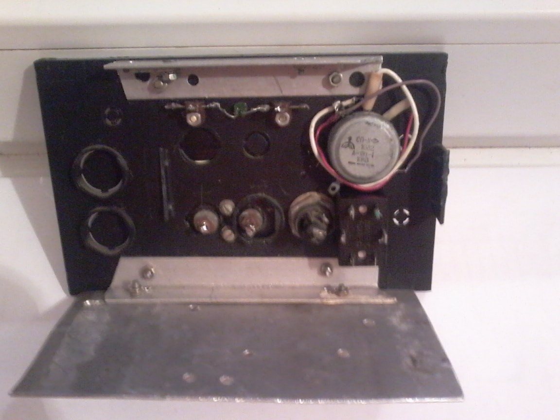
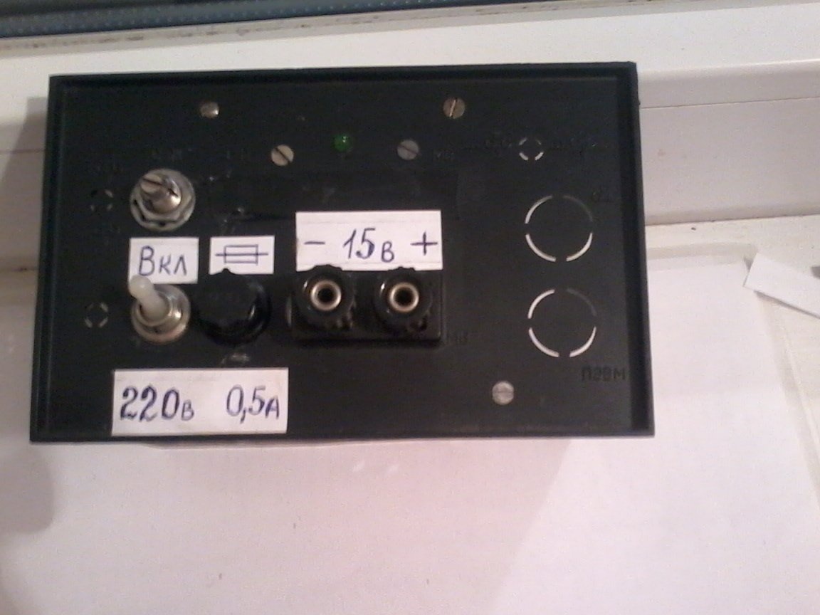
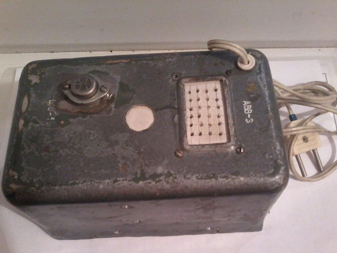
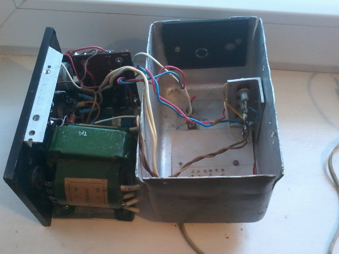
I fix a transformer, a toggle switch, a fuse holder, a variable resistor, output terminals, an LED, a mounting plate, and a C1 capacitor on the front wall of the housing. Since I had a finished aluminum case, I placed the VT3 transistor on the back of the case.
The transistor was isolated from the case using amateur radio mica and textolite bushings. Diodes placed on an aluminum corner measuring 30 by 30 by 60 mm, also insulating them from the case. Then secured them upstairs inside the enclosure.
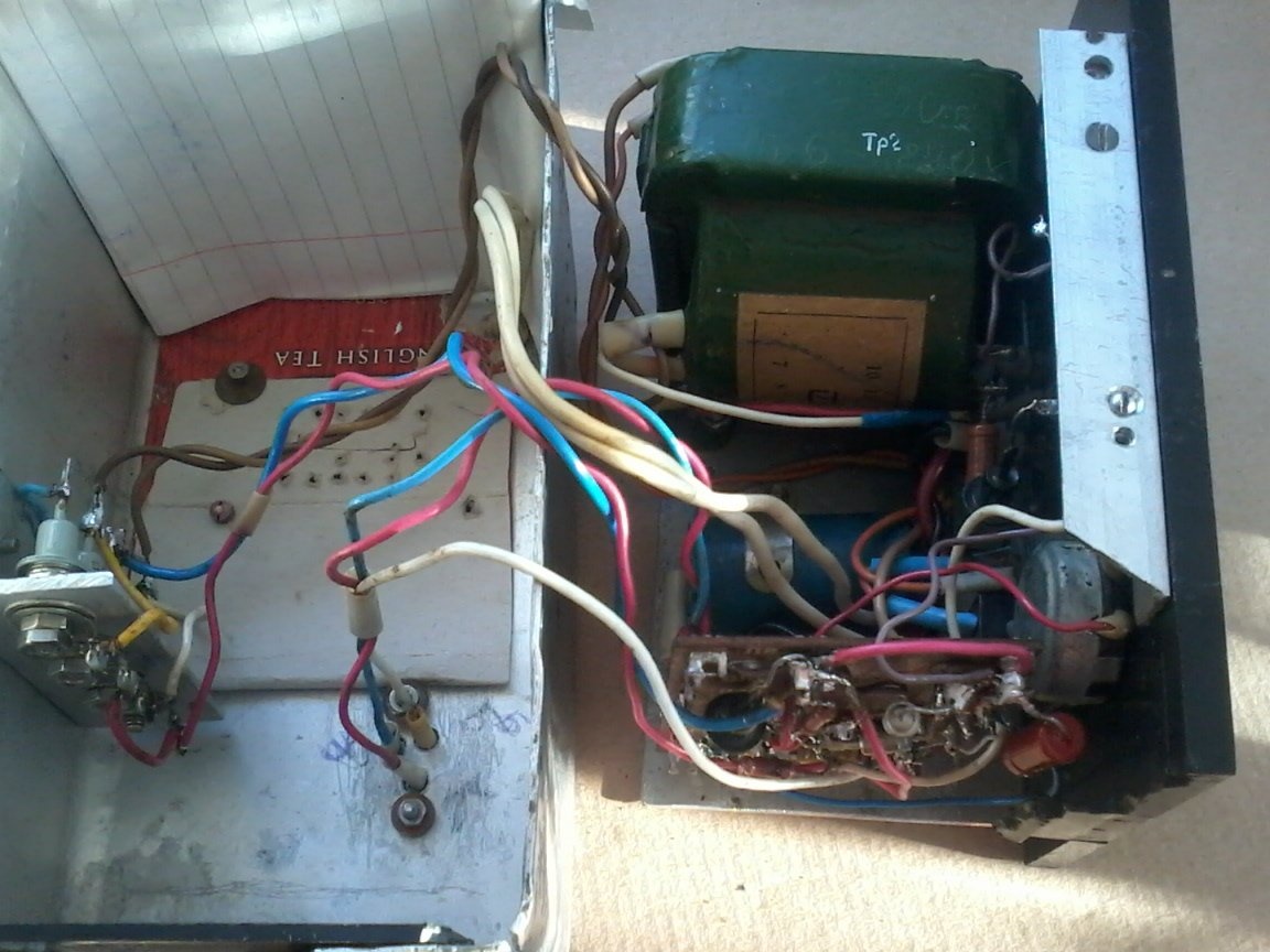
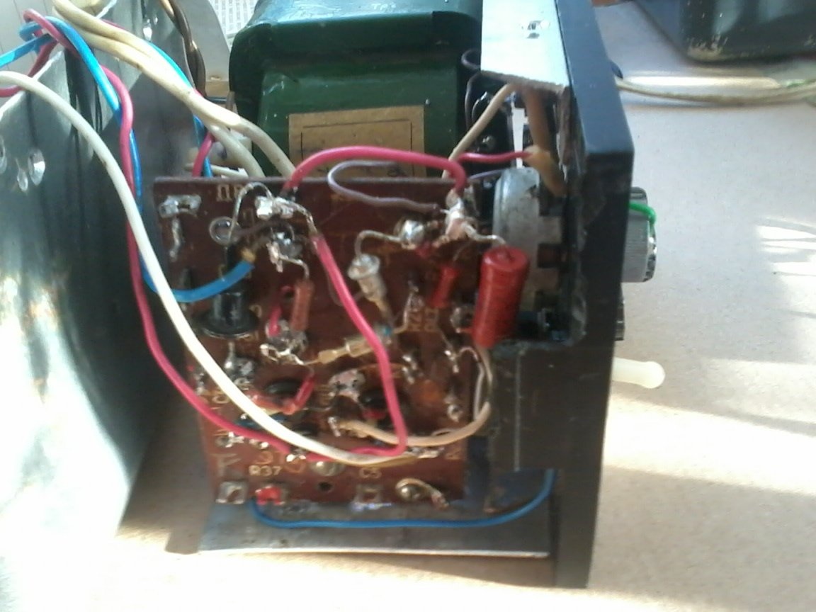
All this is shown in the photo.
Step -3.
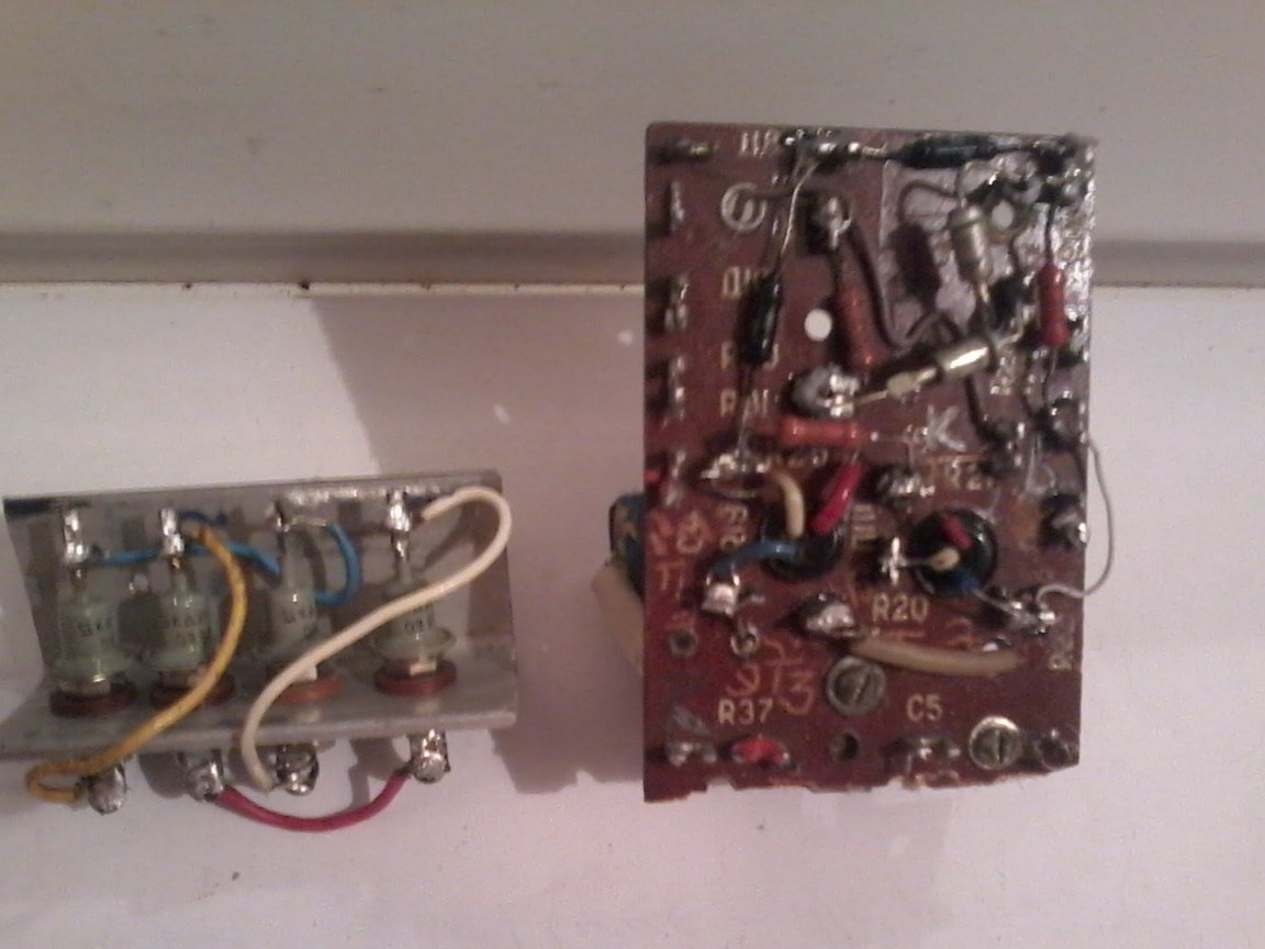
I solder the circuit on the circuit board, then all the other radio components
Step 4. Now we proceed to check the power supply with a multimeter. After supplying power to the unit, we immediately check the constant voltage across the capacitor C1 - it should be 22-25v. Then we install the resistor engine R4 in the upper position according to the scheme and measure the voltage at the clamps - it should be about 15 V. If it is much smaller, check the operation of the zener diodes - we connect a voltmeter to the conclusions of the zener diodes and measure the voltage. it should be equal to the stabilization voltage of two zener diodes, but not less than 15 volts. Otherwise, check the resistance of resistor R3. If the voltage at the zener diodes is normal, and at the output of the unit is greatly underestimated, check the health of VT2, VT3 and the correct wiring of their conclusions. When the desired voltage appears (about 15 V), we move the resistor R4 engine down according to the scheme - the output voltage should gradually decrease to almost zero. We check the operation of the unit under load. We connect to the terminals a resistor with a resistance of 30 -35 ohms and a power of at least 8 watts. Now, at the upper position of the resistor engine R4, the output voltage of the block should not be lower than 15 V. If it is lower, reduce the resistance of resistor R3 (install a resistor of 300 or 330 ohms instead). Check the action of the circuit breaker. Set the output voltage of the unit to 5 -6 V and quickly touch the clamps with the probes of an ammeter or milliammeter with a measurement limit of at least 750 mA.
At the first moment, the arrow should deviate abruptly to the final division of the scale, and then return to the zero mark. If so, the machine is working properly. Otherwise, you will have to check the health of the transistor VT1 and the correct soldering of its conclusions. Next, I make the corresponding inscriptions on the front wall of the case. The block is ready. I collected the same block in 2007. He worked with me for 12 years. I gave it to a friend, and I did it myself.