» Electronics »Homemade, extending the life of lighting lamps 220v

Homemade extending the life of lighting lamps 220v


Hello, friends the inhabitants of our site and site visitors!
I collected another homemade product that I bring to your attention. This device reduces the inrush current through the lighting lamp by 220V at the time of its inclusion, thereby extending its service life.

Many of you know how often you have to change burned out lighting lamps at home or in your apartment. This home-made lamp turns on for 2 seconds after turning on the chandelier switch. Here is a homemade scheme

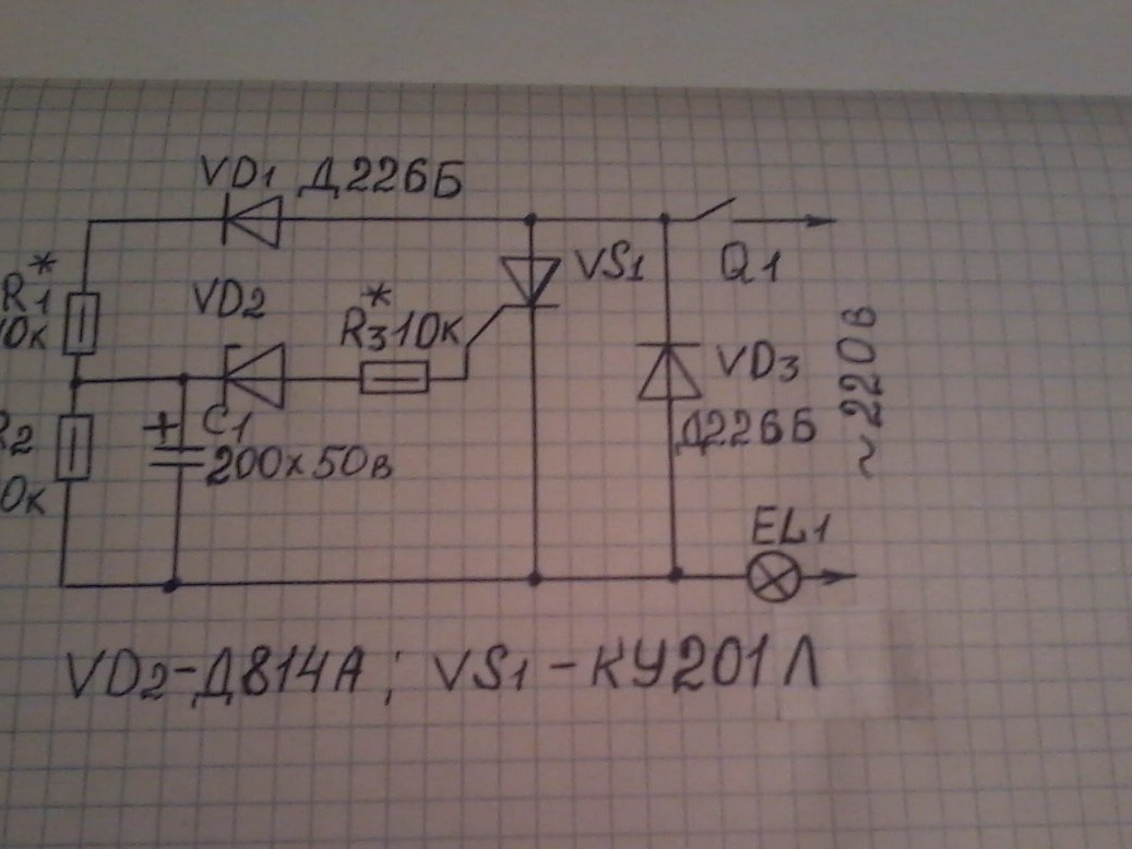
I took it from the magazine Radio No. 7 of 1988. This machine works like this. When the contacts of the Q1 switch are closed, the EL1 lamp starts to glow completely, since the current flows through it only during positive half-periods of the mains voltage on the lower, according to the scheme, power supply wire.

During negative half-cycles, capacitor C1 is charged. As soon as the voltage across the capacitor reaches the stabilization voltage of the Zener diode VD2, the thyristor VS1 opens and the lamp flashes almost to full heat. The parts shown in the diagram are designed for operation of the machine with a lamp (or lamps with power up to 150W). For a more powerful load (500-700 W), you need to install a VD3 diode with a permissible rectified current of 2 -3A, (for example, KD202L). In this case, the thyristor can not be installed on the radiator. To assemble this device, we need the following parts and tools.

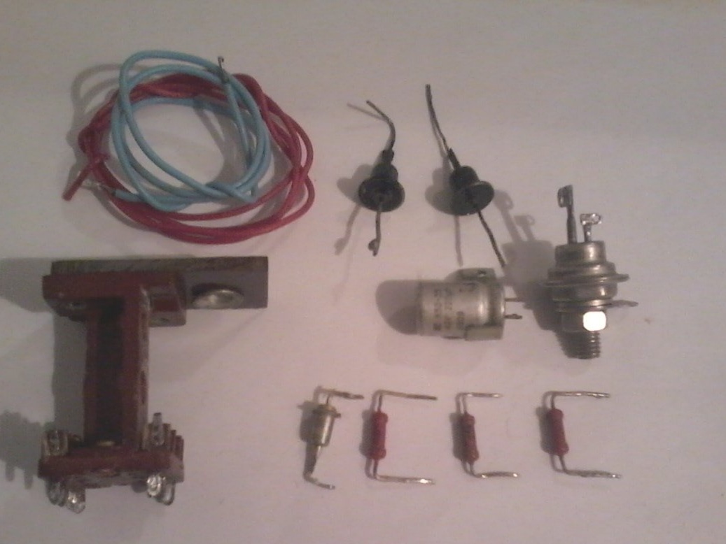
1 - a small circuit board; Thyristor KU 201L; two diodes D226B; Zener diode D814A; resistors MLT-0.5 W 120 com; and two for 10 com; 200 uF capacitor at 50 V; elektrolampa 95 W 220V for setting up the machine.

2 - mounting wires; soldering iron; solder; tweezers; Variable resistor Sp -1 22kom for tuning; nippers; pliers; multimeter; drill, drill. We assemble the device as follows.

Step 1. We check all the radio components for their serviceability.


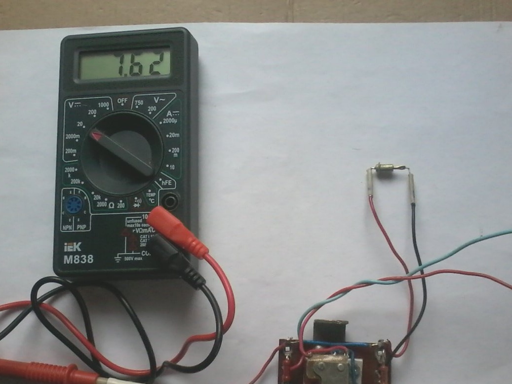
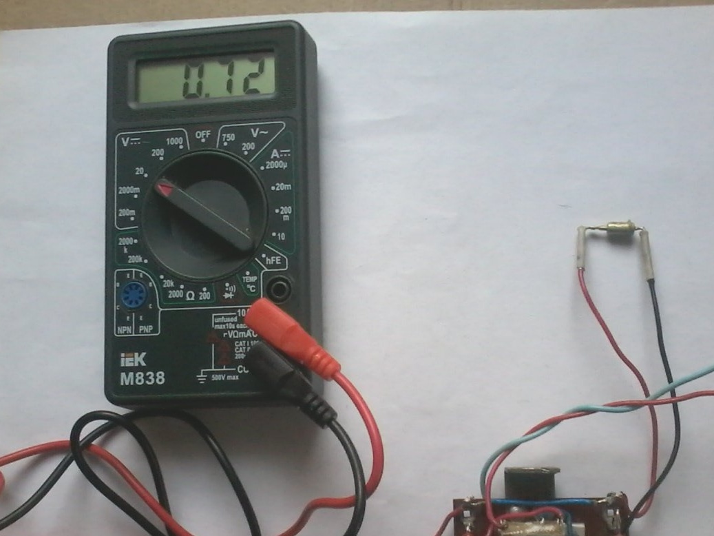
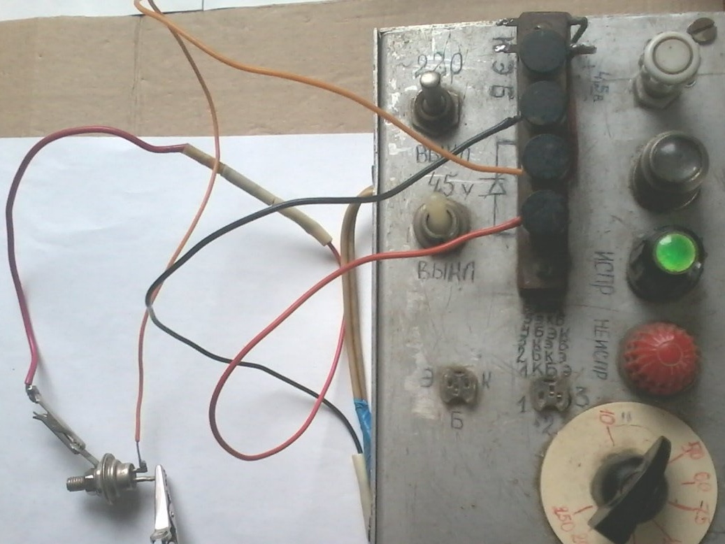
Moreover, I checked the thyristor and the zener diode with my previously made home-made products.

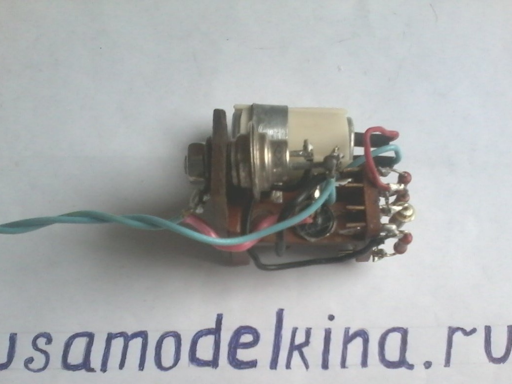
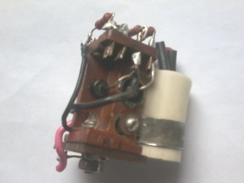
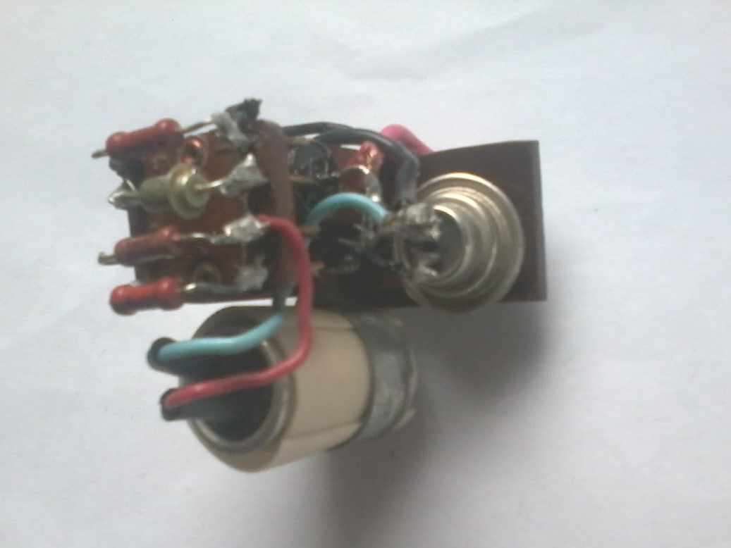
Step 2. Install the thyristor, diodes and capacitor on the circuit board.

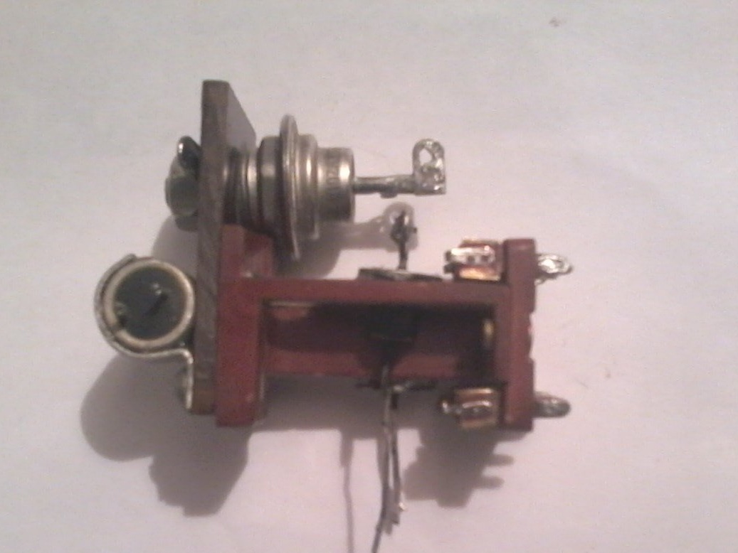
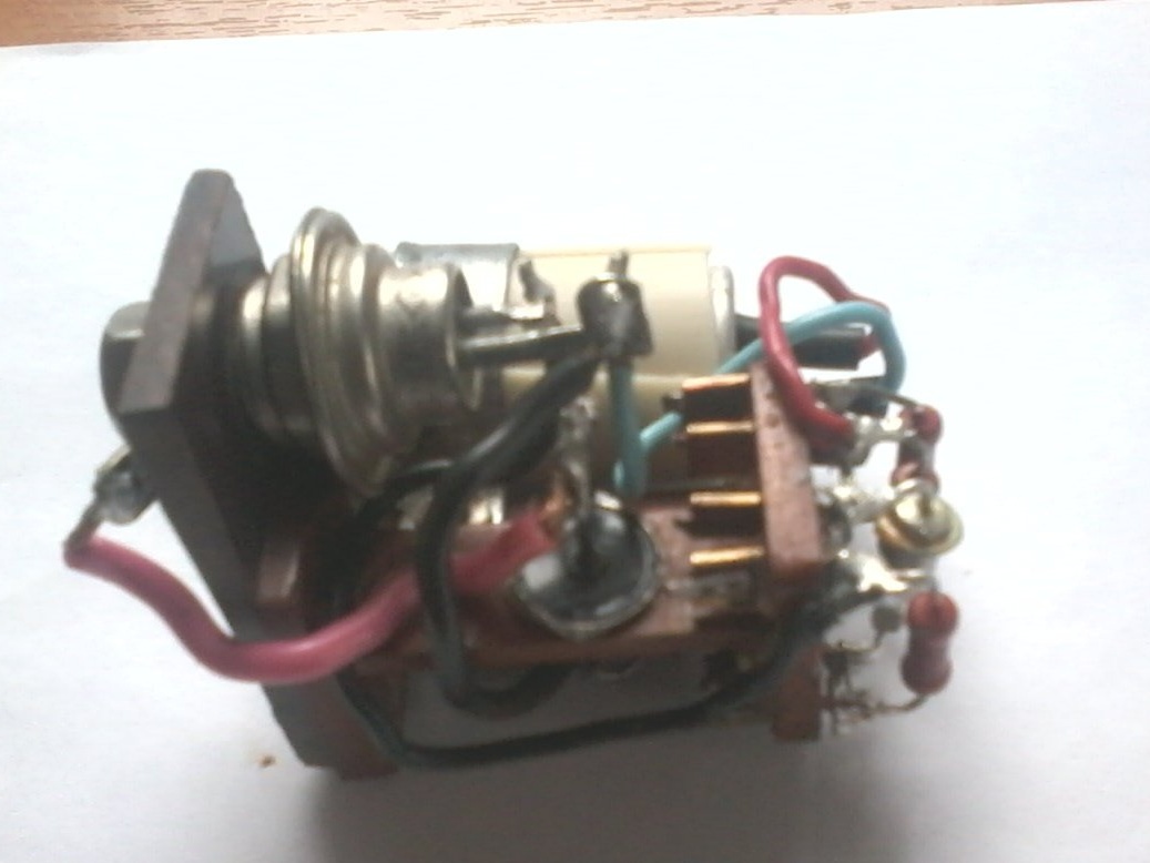
Step 3. We solder the entire circuit of the device, check the correct assembly. The whole process of verification and assembly is shown in the photo.


Step 4We are setting up the device. To do this, turn off the VD3 diode. Instead of resistor R3, we temporarily solder a variable resistor with a resistance of 22 kΩ. A few seconds after turning on the device, the EL1 lamp should light up with a blinking light. If the lamp does not light, we select the current of the thyristor control electrode with a variable resistor. Then we measure the voltage across the capacitor C1. If it exceeds 50 V, Replace the capacitor with another one with a large rated voltage. After that, we connect the VD3 diode and measure the alternating voltage on the lamp. You can change it in one direction or another by selecting the resistor R1, but it is undesirable to significantly reduce the resistance of the resistor compared to that indicated on the circuit, otherwise the duration of the preliminary heating of the lamp filament will decrease (it should not be less than 2 seconds) - until the thyristor is turned on.

Here is a simple homemade product that extends the life of lighting lamps. The assembled device must be placed in a suitable plastic case and placed in a chandelier, connecting the lamps according to the diagram. I wish you all great success in your work.
5.7
8.1
6.9

Add a comment

    • smilesmilesxaxaokdontknowyahoonea
      bossscratchfoolyesyes-yesaggressivesecret
      sorrydancedance2dance3pardonhelpdrinks
      stopfriendsgoodgoodgoodwhistleswoontongue
      smokeclappingcraydeclarederisivedon-t_mentiondownload
      heatirefullaugh1mdameetingmoskingnegative
      not_ipopcornpunishreadscarescaressearch
      tauntthank_youthisto_clueumnikacuteagree
      badbeeeblack_eyeblum3blushboastboredom
      censoredpleasantrysecret2threatenvictoryyusun_bespectacled
      shokrespektlolprevedwelcomekrutoyya_za
      ya_dobryihelperne_huliganne_othodifludbanclose
7 comments
Nick
I made low-power power supplies from the electronics of compact luminescent blocks .... A lot of circuits in the internet ...
Guest Ivan
Isn’t it easier to put a varistor in a parallel with a light bulb?
So somehow passed by me.
I mentioned "Granite"as the most common. In addition to him, in the 2000s, a lot of cheaper different lamp protection units appeared. In each "electric shop" there were billboards ... Now it’s somehow gone ...
The first time I hear that there were some Granites. Maybe progress has not reached us? But what about compact luminescent, can you adapt electronics from it anywhere? I have several large lamps of such a workshop. I opened a couple, I look swollen Conder on both.
Good and necessary homemade ... But ... WAS!
It was good and necessary ...)))
In the 88th year, when her scheme was published, she had no price at all ... As in the 90s ...
But already in the 2000s, "Granites" appeared and others like them ... Which cost quite a penny and were compact. It became easy to place them behind the switches ... (The case when you just do not have to do it yourself, because as purchased - it is both better and cheaper)))
In 2007, it seems that I protected all the lamps in the new apartment. As a result - until the "era of energy saving" bulbs, I burned out about five, maximum. (This is despite the fact that there were only 50 of them in the apartment (halogen and glow) !!!
The necessary thing ... I even agree that somewhere there is not a large number of shops specializing in chandeliers and switches ... And in the local general store, or even a department store, there are only bulbs ...
..But this period has ended !!! The era of incandescent lamps is gone !!! At first they flickered and disappeared like Windows Vista compact luminescent ... And then the diodes poured !!! ....
P.S. I have eight "Granites" ... I poked it out from under the switches and from suspended ceilings ... Diodes are not always friendly with them ...
I’ll tell you how I made such a regulator, but just immediately I ask you strongly not to throw your slippers, because the methods used were barbaric. To reduce the dimensions of the thyristor and diodes (I had KD 202), the upper conclusions were first bitten off in the most cruel way, then the trepanation of the case was made, followed by soldering of the crystals. Then everything was collected on a signet and filled with epoxy, the dimensions were reduced by 2-3 times. By the way, in the same way, diode bridges were made instead of the CC, which were more difficult to get at the plant than even scarce thyristors.

We advise you to read:

Hand it for the smartphone ...