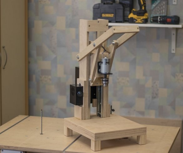
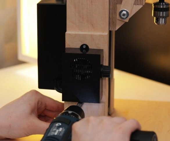
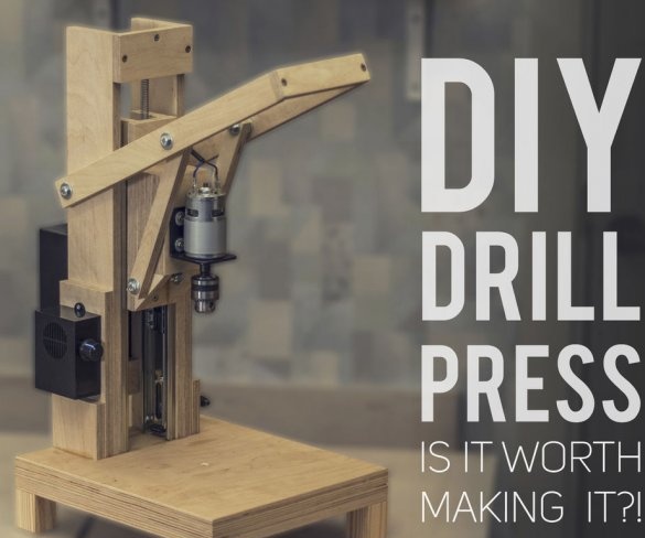
In this manual, the master presents his developed home-made drilling machine with a model 775 motor. Its speed is controlled by a 10A PWM speed controller. He also provides tests to decide whether it is worth the time and effort to create such a tool.
Tools and materials:
-Drill;
- Electric jigsaw;
- Clamps;
-Gon;
-Soldering accessories;
- Plywood 12 mm thick;
- Plywood 18 mm thick;
- Guides 30cm;
-Springs;
- DC motor model 775 or 895;
- Cartridge 0.6-6 mm;
- Bracket for 775 engine;
- Speed controller 10A;
- Speed controller 20A for the engine 895;
-24V 5A power supply for the 775 engine;
- Power supply 24 V, 10 A for 895 engine;
-Fasteners;
- Joiner's glue;
-Wire;
- Hacksaw for metal;
Step One: 3Dmodel
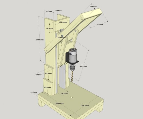
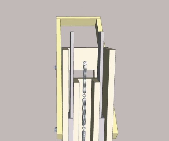
Before starting the manufacture of the machine, the master develops its 3D model in a graphics program.
Step two: procurement of parts
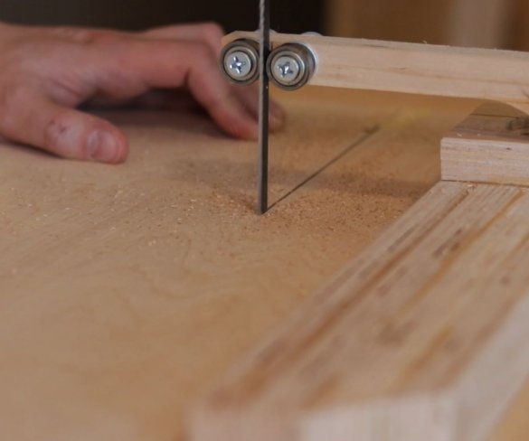
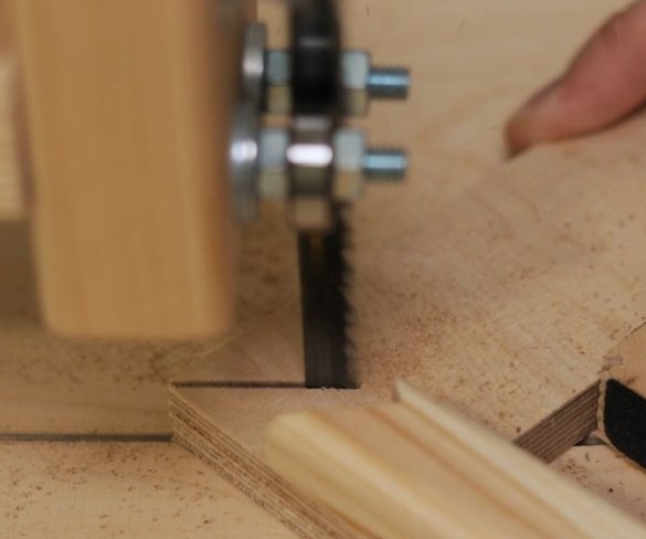
Cut parts of the future machine according to size. Part size file can be downloaded here.
Step Three: Guides
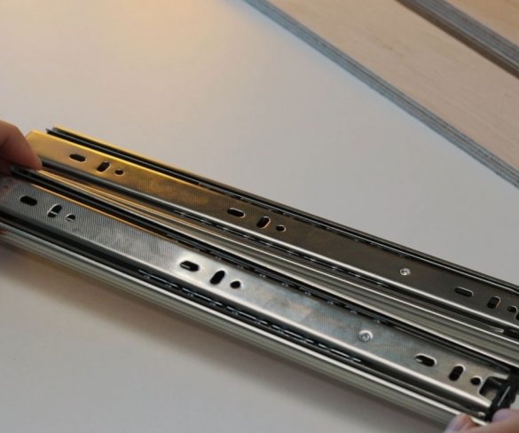
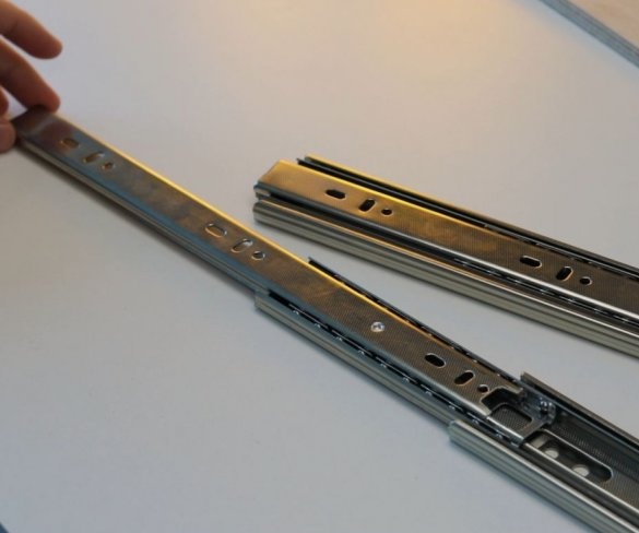
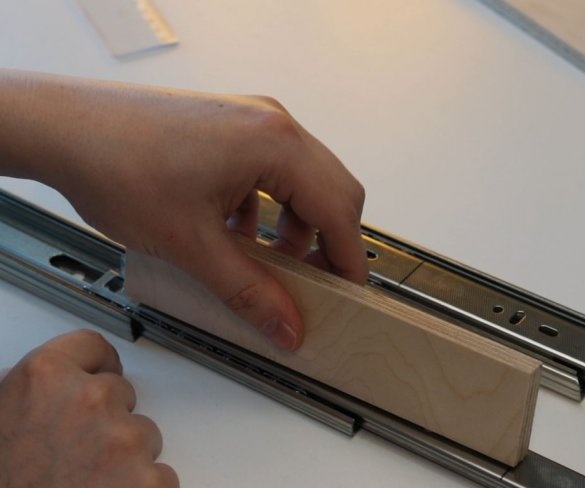
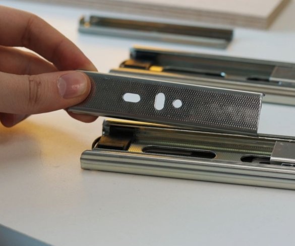
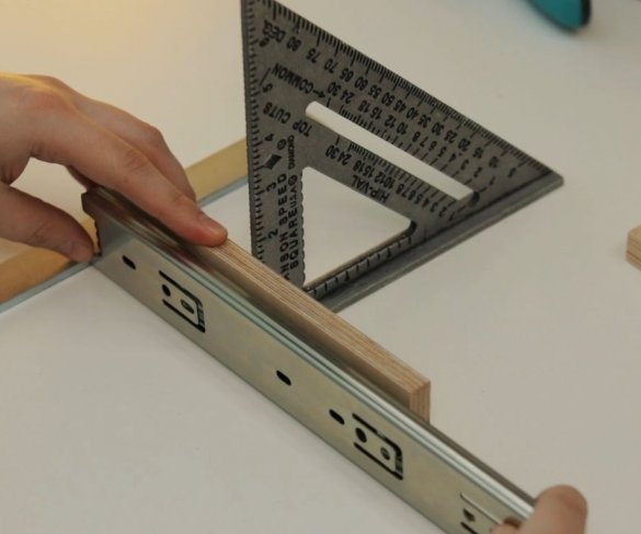
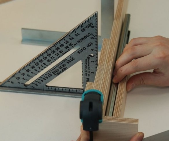
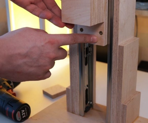
To move the working part of the machine up and down, the master used a pair of powerful furniture guides. The use of furniture rails is an excellent solution for this task.
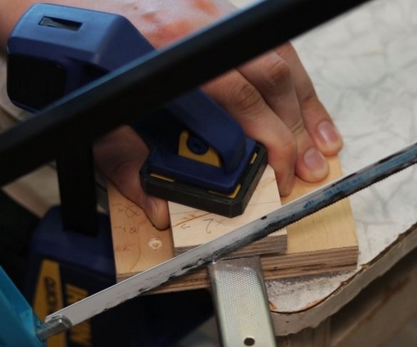
The moving part of the drill is shorter than the length of the guides, so part of the guides is cut off.
Step Four: Uprights
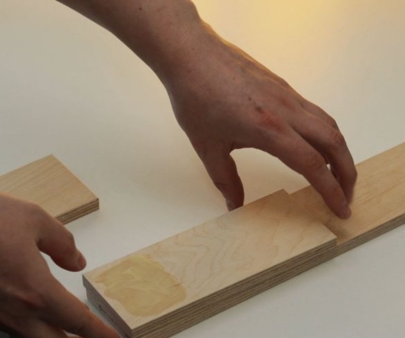
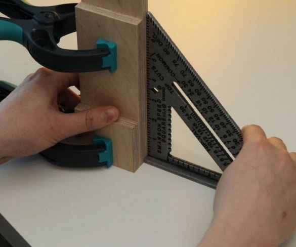
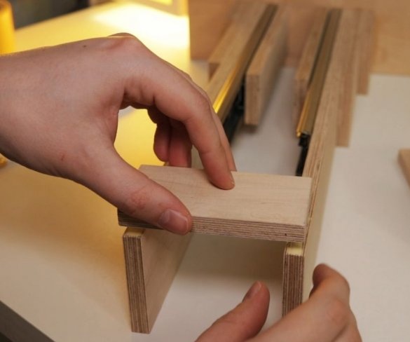
The master made vertical racks by gluing previously cut parts.
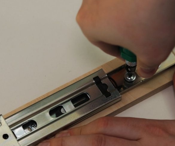
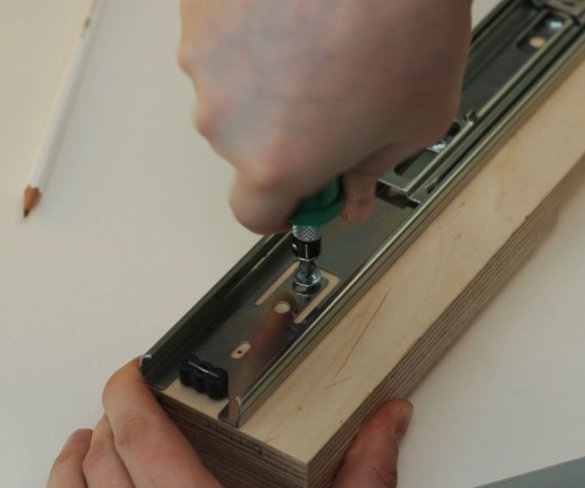
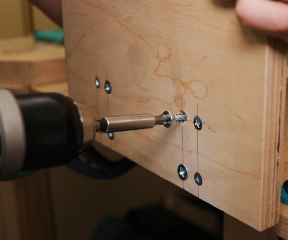
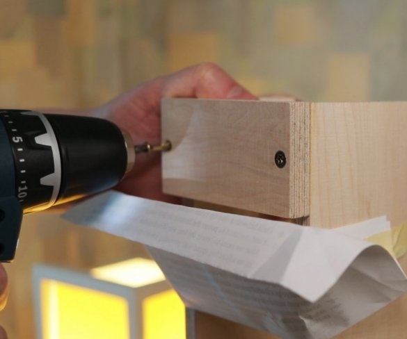
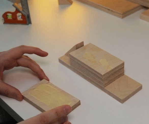
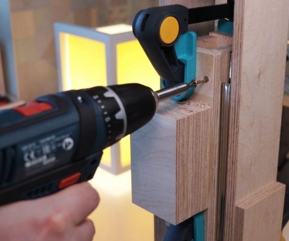
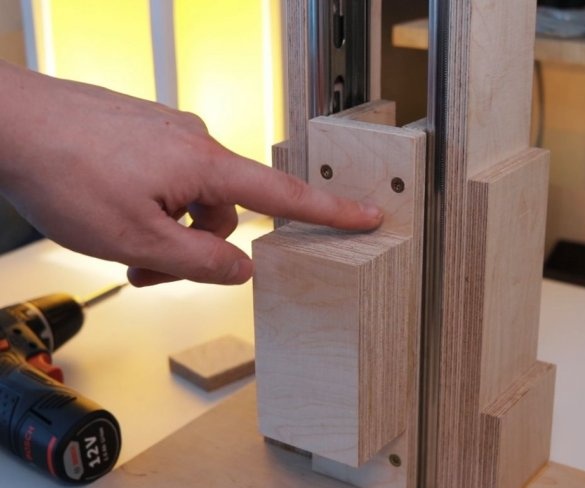
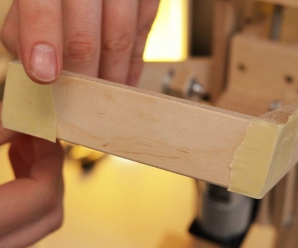
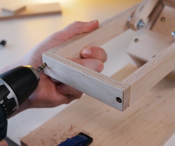
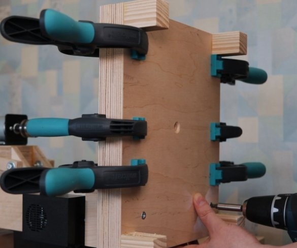
To easily attach the guides to the inside of the wizard, first glued both parts using double-sided adhesive tape, and then secured it with a pan-head screw. In the same way, he secured the other side of the slider on the previously glued part.
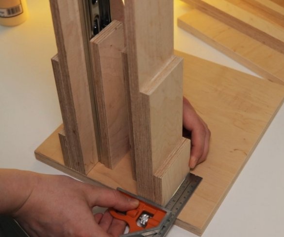
Now both vertical posts can be attached to the base. The master applies glue to the mating surfaces and then fastens the posts to the base. At the top of the struts, a transverse bar is screwed.
Step Five: Platform
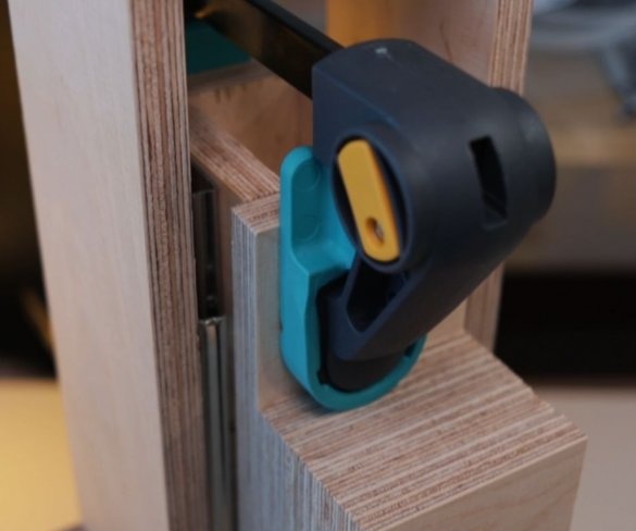
Now you need to make a platform on which the engine will be fixed and which will move. The master glues the platform parts and fastens the second halves of the guides.
Step Six: Engine Installation
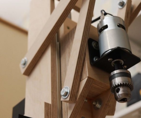
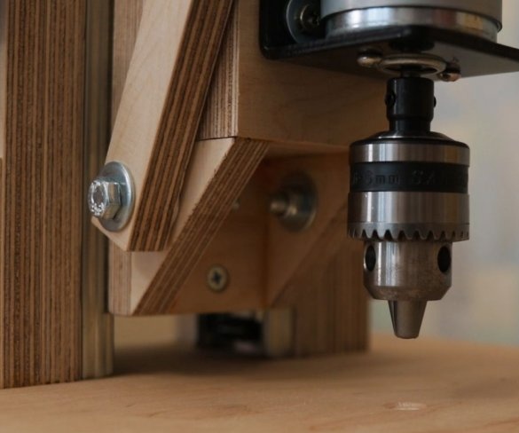
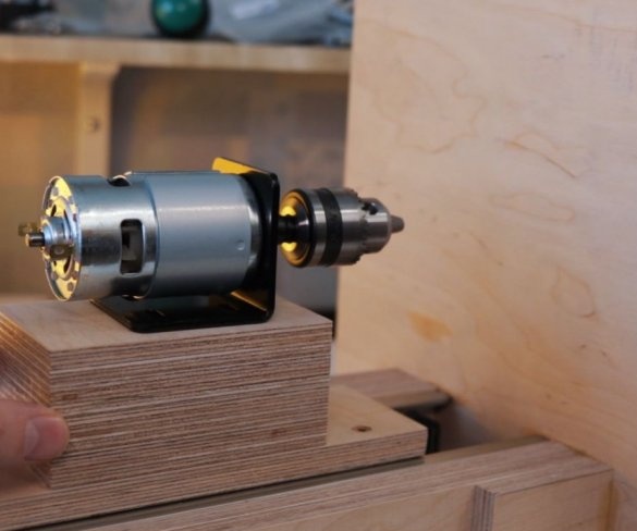
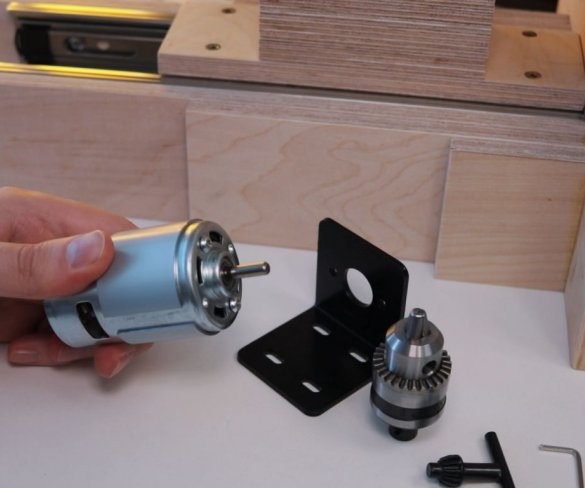
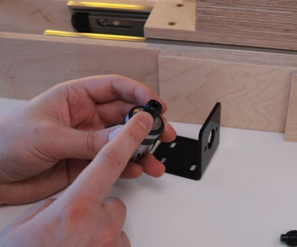
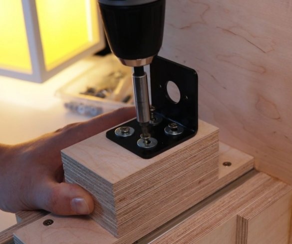
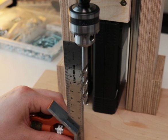
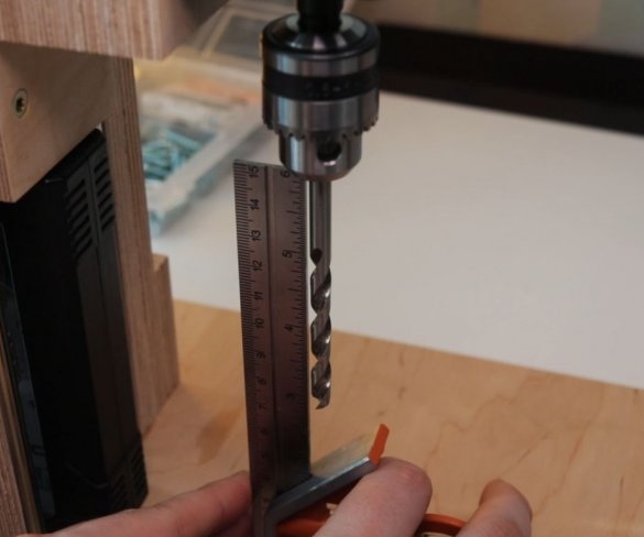
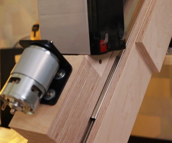
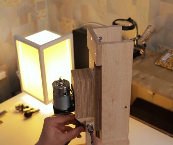
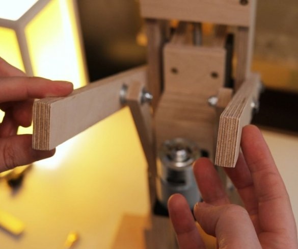
Screws the bracket to the platform. Secures the engine to it. It is important to maintain an angle of 90 degrees.
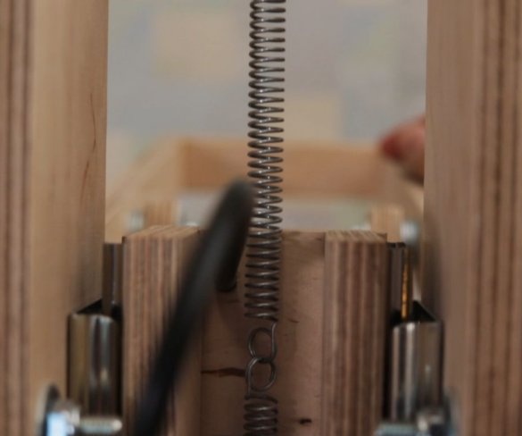
Seventh step: spring
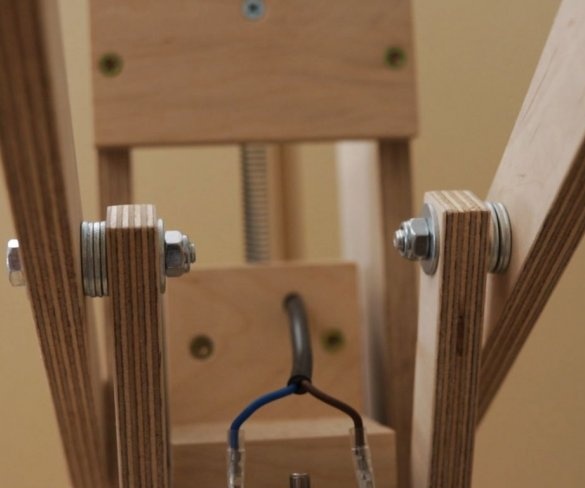
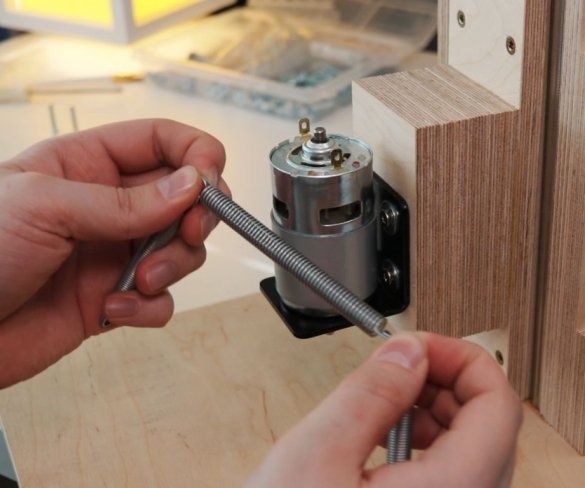
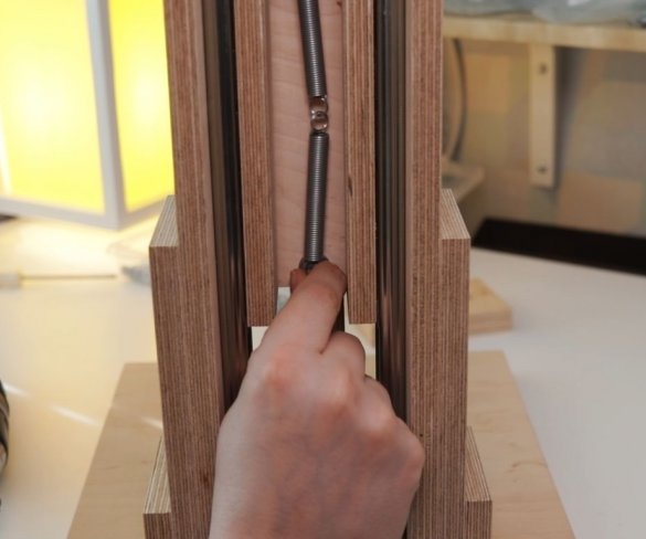
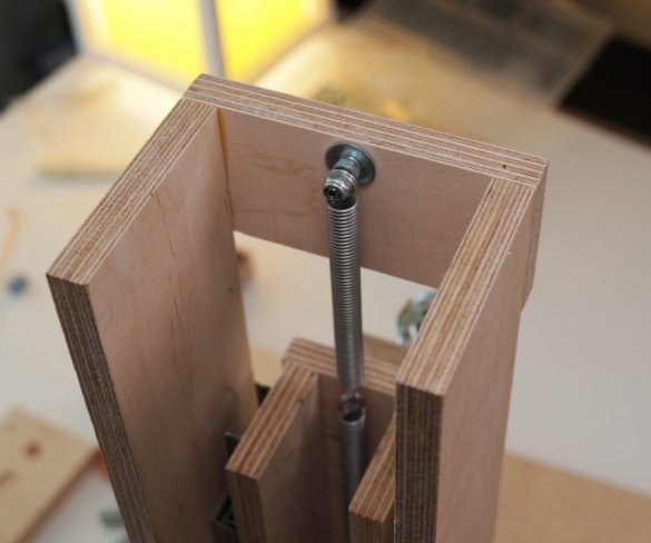
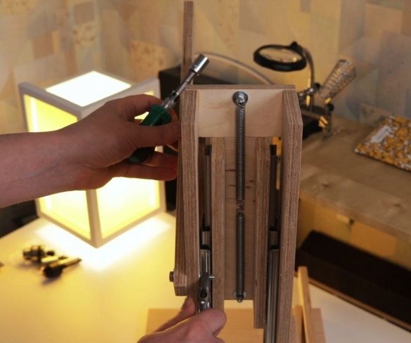
The easiest way to lift the engine up is to use springs. The master secures the spring with bolts, washers and self-locking nuts.
Step Eight: Lever
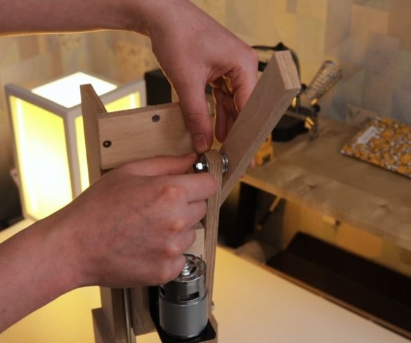
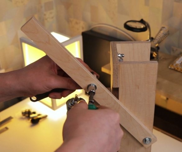
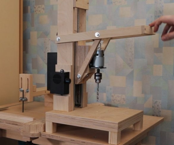
Then the master makes and sets the lever.
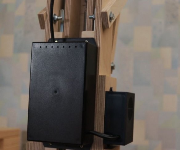
Step nine: electrical part
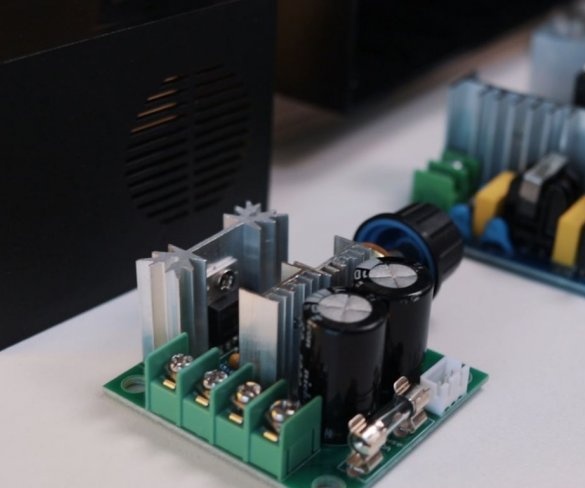
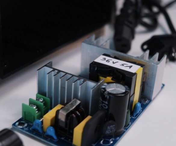
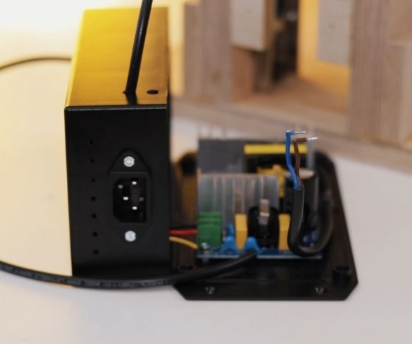
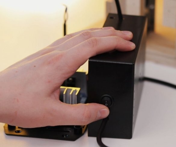
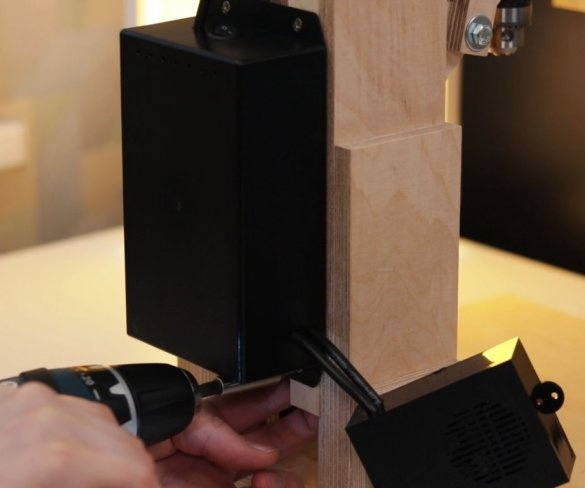
To control the speed of the engine, the master used a conventional speed controller. I used a 36 V 5A power supply to power the engine.
When testing, using a 6 mm wood drill, the master found out the following: you can easily connect this engine to a 24 V 5 A. power supply. 36V is a kind of excess, but the master just had this power supply, so he used it. When using a 12 V power supply, the engine simply stalls when drilling harder wood.
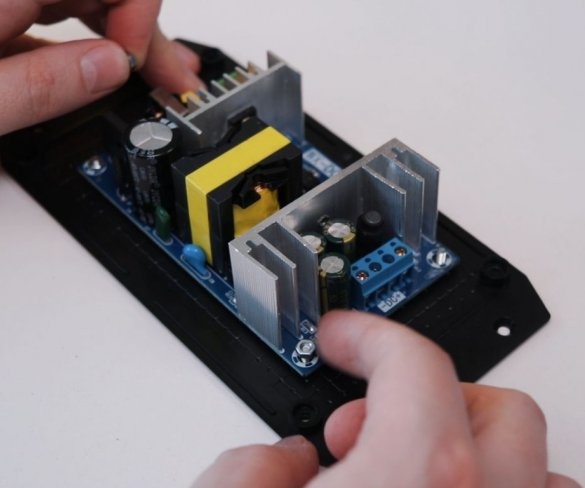
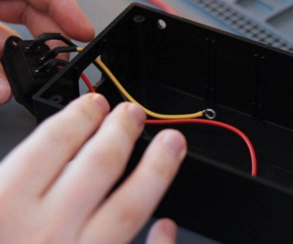
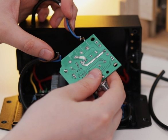
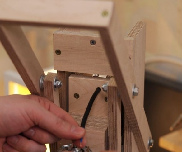
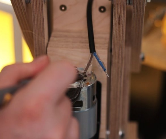
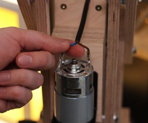
Installation of electrical parts is simple. From the power supply there is a wire to the speed controller + and -, and from the controller to the engine.
Step Ten: Foundation
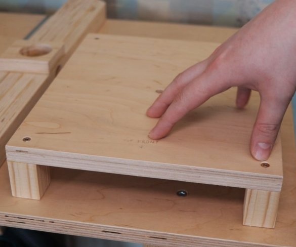
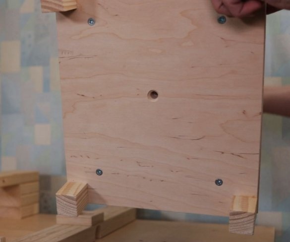
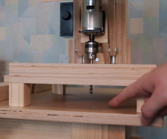
The master lifted the base above the surface with the help of four bars fixed from the bottom.
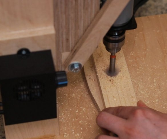
Step Eleven: Test
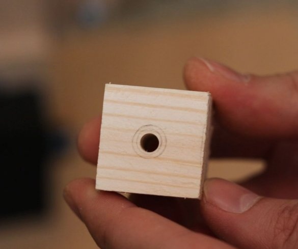
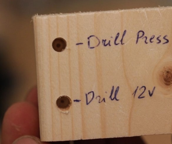
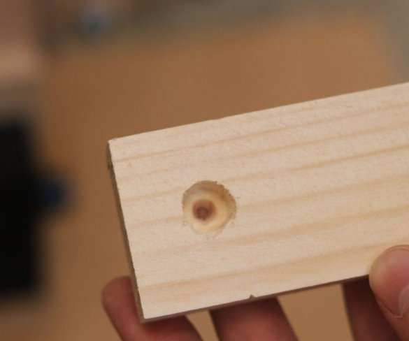
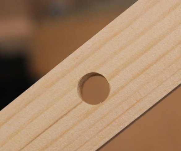
Here are some test results. All tests can be seen at the beginning and at the end of the video.
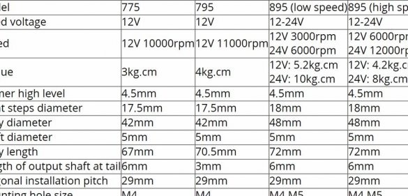
This drilling machine turned out to be inexpensive to manufacture, and the drill really drills a maximum of 6 mm holes. For large openings, the 775 engine simply lacks torque. You can apply more voltage to get a higher torque, but then it rotates too fast.
You can also use the model 895 motor (24 V 6000 rpm, low-speed version), which has almost twice as much torque.
In conclusion, the master says that if you need a tool for drilling small perpendicular holes in wooden materials, then a drilling machine like this works pretty well. It makes quick holes and is not expensive. To drill holes of large diameter it is better to use another machine.
The whole process of manufacturing the machine can be seen in the video.

