
Inverter 12 -220 volts on Arduino pure sine with full program code.
Theory
Achieving a sine wave output is quite difficult and cannot be recommended for inverters, because electronic devices usually do not like exponentially increasing currents or voltages. Since inverters are mainly manufactured using solid state electronic devices, a sinusoidal waveform is usually eliminated.
Electronic power devices when working with sinusoidal waves give ineffective results, since devices, as a rule, are heated in comparison with rectangular pulses.
Thus, the best option for implementing a sine wave on an inverter is PWM, which means pulse width modulation or PWM.
PWM is an improved way (digital version) of exponential waveform exposure through proportionally changing square pulse widths, the net value of which is calculated exactly in accordance with the net value of the selected exponential waveform, here the "pure" value refers to the RMS value. Therefore, the calculated PWM with reference to a given sine wave can be used as an ideal equivalent for replication of a given sine wave. In addition, PWMs will be ideally compatible with electronic power devices (mosfets, BJTs, IGBTS) and allow their use with minimal heat.
What is SPWM?
The most common method is to produce a PWM sinewaver (sine wave) or SPWM, by applying several exponentially variable signals to the input of an operational amplifier for the necessary processing. Among the two input signals, one should be much higher in frequency compared to the other.
Using two input signals
As mentioned in the previous section, the procedure involves supplying two exponentially varying signals to the inputs of the operational amplifier.
Here, the operational amplifier is configured as a typical comparator, so we can assume that the operational amplifier will immediately begin to compare the instantaneous voltage levels of these two superimposed signals at the moment they appear or are applied to its inputs.
In order for the operational amplifier to correctly implement the necessary sinusoidal PWM at its output, it is necessary that one of the signals has a much higher frequency than the other. The slower frequency here is that which should be the sine wave of the sample, which should be simulated (replicated) by PWMs.
Ideally, both signals should be sinusoidal (one with a higher frequency than the other), however, the same can be realized by including a triangular wave (high frequency) and a sine wave (selective wave with a low frequency). As can be seen in the following images, the high-frequency signal is invariably fed to the inverting input (-) of the operational amplifier, while another slower sinusoidal signal is supplied to the non-inverting (+) input of the operational amplifier. In the worst case, both signals may be triangular waves with recommended frequency levels, as described above. However, this will help in achieving a reasonably good equivalent of PWM sinewave.
A signal with a higher frequency is called a carrier signal, while a slower sample signal is called a modulating input.
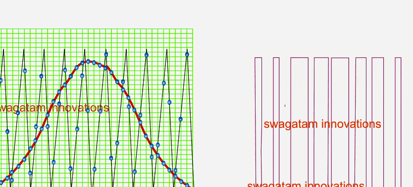
Create SPWM with a triangular and tendon wave
Referring to the above figure, it is possible to clearly visualize through the plotted points the various coincident or overlapping voltage points of the two signals for a given period of time. The horizontal axis shows the time period of the waveform, while the vertical axis shows the voltage levels of 2 simultaneously running, the superimposed waveform. The figure informs us how the operational amplifier will respond to the shown matching instantaneous voltage levels of the two signals and produce a correspondingly changing sinusoidal PWM at its output. An operational amplifier (op-amp) simply compares the voltage levels of a fast triangle wave instantly changing a sine wave (it can also be a triangle wave), and checks for cases in which the voltage of the triangle waveform can be lower than the voltage of the sine wave and responds immediately create high logic on your exits.
This is maintained as long as the potential wave of the triangle continues to be lower than the potential of the sine wave, and the moment when the potential of the sine wave is detected to be lower than the instantaneous potential of the wave of the triangle, the outputs return with a minimum and withstand until the situation repeats.
This continuous comparison of the instantaneous potential levels of two superimposed waveforms at the two inputs of the operational amplifiers leads to the creation of correspondingly changing PWMs, which can accurately repeat the sinusoidal shape applied to the non-inverting input of the operational amplifier.
Operational Amplifier and SPWM
The following figure shows modeling the above operation:
Here we can observe how it is implemented in practice, and this is how the operational amplifier will do the same (although at a much higher speed, in the MS).
The operation is quite obvious and clearly shows how the operational amplifier should process the PWM sine wave by comparing two simultaneously changing signals at its inputs, as described in the previous sections.
In fact, the operational amplifier will process the sinusoidal PWM much more accurately than the simulation shown above, it can be 100 times better, creating extremely uniform and well-measured PWM that matches the supplied sample. Sine wave.
Arduino inverter two circuits
parts list
All 1/4 Watt Resistors, 5% CFR
• 10K = 4
• 1K = 2
• BC547 = 4pcs
• MOSFETs IRF540 = 2pcs
• Arduino UNO = 1
• Transformer = 9-0-9V / 220V / 120V.
• Battery = 12V
All 1/4 Watt Resistors, 5% CFR
• 10K = 4
• 1K = 2
• BC547 = 4pcs
• MOSFETs IRF540 = 2pcs
• Arduino UNO = 1
• Transformer = 9-0-9V / 220V / 120V.
• Battery = 12V
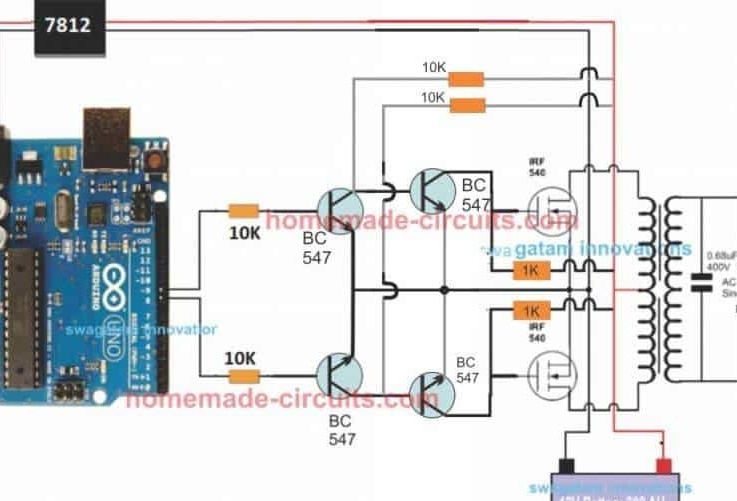
The design is actually very simple, as shown in the following figure.
Pin # 8 and pin # 9 create PWM alternately and switch Mosfets with the same PWM.
Mosfet, in turn, induces a highly current SPWM waveform on the transformer, using the power of the battery, forcing the secondary of the transformer to produce an identical waveform.
The proposed Arduino inverter circuit can be upgraded to any preferred higher power level by simply replacing the Mosfets and transformer, respectively, as an alternative, you can also convert this to a full bridge or H-bridge sine wave inverter
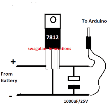
Arduino Board Power
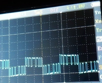
Waveform Images for Arduino SPWM
Since the Arduino will produce a 5V output, this may not be ideal for directly controlling MOS transistors.
Therefore, it is necessary to raise the strobe level to 12V so that the Mosfets will work correctly without heating the devices.
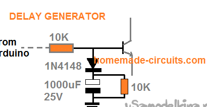
To make sure that Mosfety does not start when Arduino starts or starts, you need to add the following delay generator and connect it to the base of BC547 transistors. This will protect Mosfets and prevent them from burning out during a power switch and when Arduino boots up.
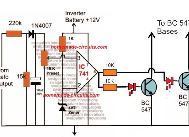
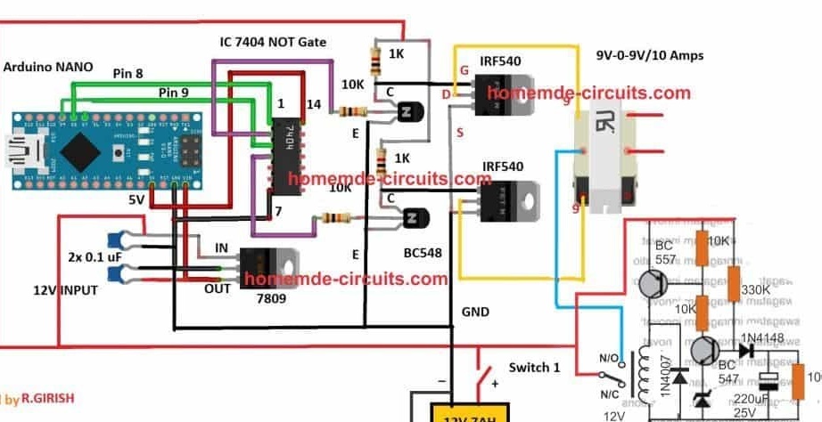
Adding an Automatic Voltage Regulator
Just like on any other inverter, at the output of this design, the current can rise to unsafe limits when the battery is fully charged.
To control this, add an automatic voltage regulator.
The BC547 collectors must be connected to the bases of the left BC547 pair, which are connected to the Arduino via 10K resistors.
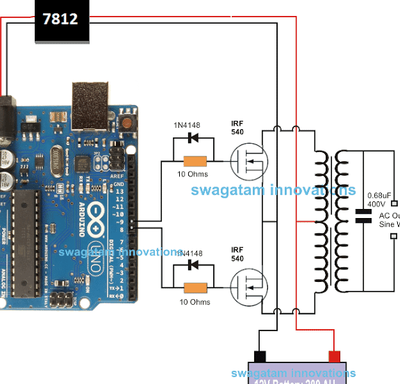
The second version of the inverter using the sn7404 / k155ln1 chip
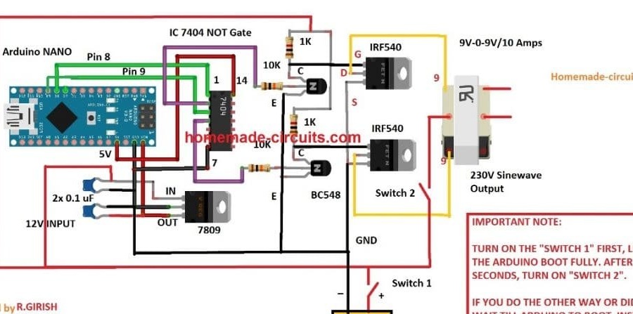
Important:
To avoid accidental switching on before loading the Arduino, a simple delay in the timer circuit can be included in the above design, as shown below:
Program code:
/ *
This code was based on Swagatam SPWM code with changes made to remove errors. Use this code as you would use any other Swagatam’s works.
Atton risk 2017
* /
const int sPWMArray [] = {500,500,750,500,1250,500,2000,500,1250,500,750,500,500}; // This is the array with the SPWM values change them at will
const int sPWMArrayValues = 13; // You need this since C doesn’t give you the length of an Array
// The pins
const int sPWMpin1 = 10;
const int sPWMpin2 = 9;
// The pin switches
bool sPWMpin1Status = true;
bool sPWMpin2Status = true;
void setup ()
{
pinMode (sPWMpin1, OUTPUT);
pinMode (sPWMpin2, OUTPUT);
}
void loop ()
{
// Loop for pin 1
for (int i (0); i! = sPWMArrayValues; i ++)
{
if (sPWMpin1Status)
{
digitalWrite (sPWMpin1, HIGH);
delayMicroseconds (sPWMArray [i]);
sPWMpin1Status = false;
}
else
{
digitalWrite (sPWMpin1, LOW);
delayMicroseconds (sPWMArray [i]);
sPWMpin1Status = true;
}
}
// Loop for pin 2
for (int i (0); i! = sPWMArrayValues; i ++)
{
if (sPWMpin2Status)
{
digitalWrite (sPWMpin2, HIGH);
delayMicroseconds (sPWMArray [i]);
sPWMpin2Status = false;
}
else
{
digitalWrite (sPWMpin2, LOW);
delayMicroseconds (sPWMArray [i]);
sPWMpin2Status = true;
}
}
}Good luck.