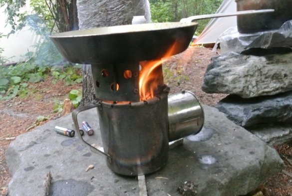
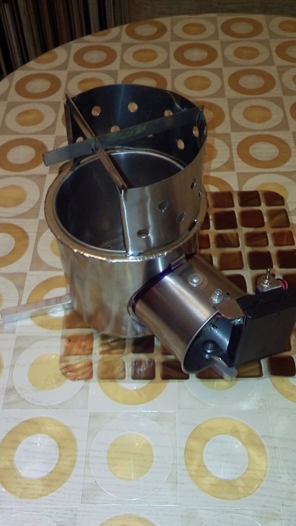
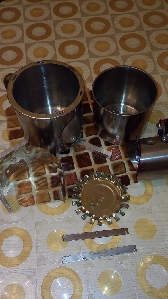
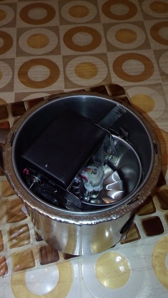
Hello. On the Internet, many walks of turbocharged chipper stove designs. I do not pretend to be the authorship of the very principle of the design of the furnace - the grate, but having considered many options, I also offer my own version of the change in design.
Tool
- screwdriver;
- drill;
- a hacksaw for metal;
- engraver;
- manual exhaust riveter;
- pliers;
- vise;
- a set of files;
- screwdrivers.
Materials
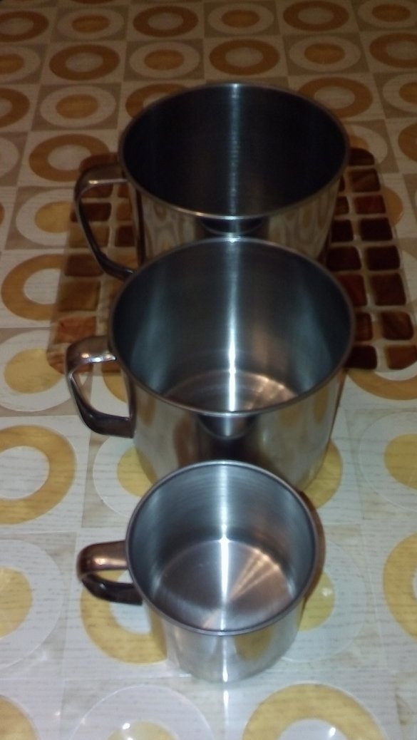
- a set of mugs made of stainless steel 13, 12, 7.5 cm;
- stainless steel sheet with a thickness of 0.8 mm;
- U-shaped profile 10 x 10 mm;
- blind rivets 2.4 and 3.2 mm;
- solder;
- a set of cutting discs.
Manufacturing process
There are many designs of woodchip stoves on the Internet. For the most part, mugs made of food stainless steel are used as the basis for the design of furnaces, the sizes and shapes of which are diverse.
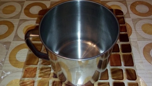
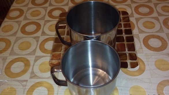
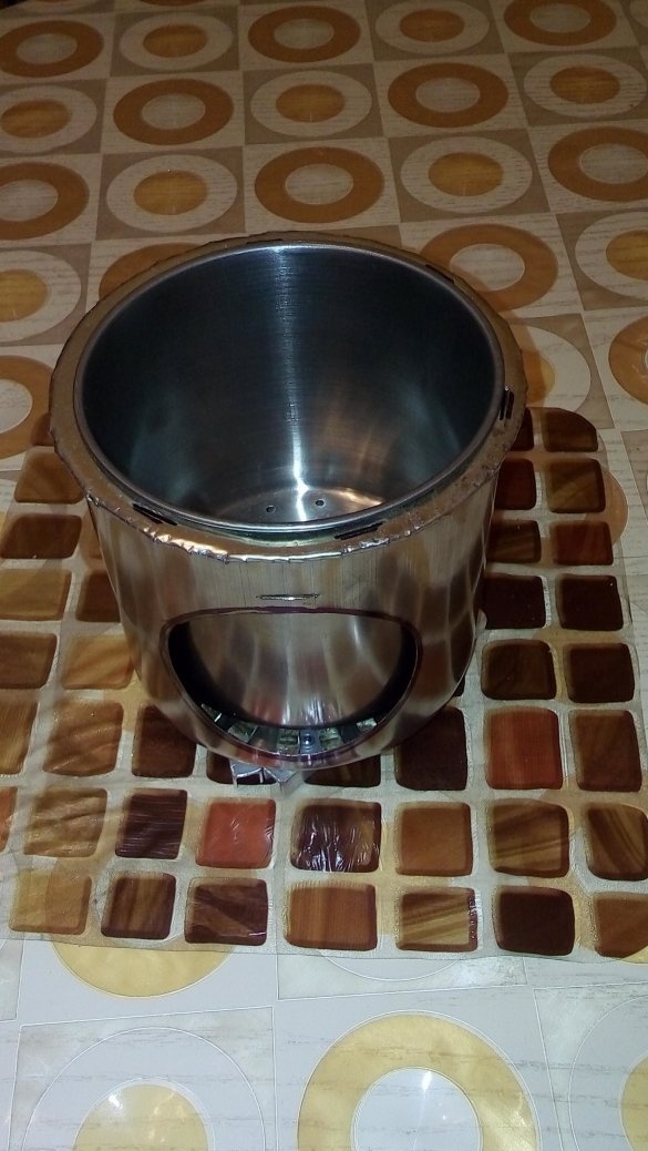
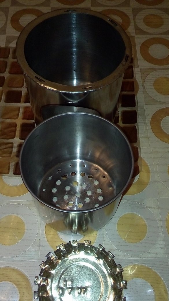
I did not become sophisticated and also acquired several mugs of different sizes, in particular with a diameter of 13, 12 and 7.5 cm. (Photo 1,2, 3).
On the Internet, it is proposed to cut a hole in the bottom of a larger mug so that a mug of a slightly smaller diameter (without a handle) is inserted into this hole - a firebox. Then, holes are made in the bottom of the smaller mug for the flow of air into the furnace.
Well, then, in a larger mug for boost, a hole is made for the turbine itself.
I did not make a hole in the bottom of a larger circle. This eliminates the loss of ash and coal on the underlying surface (earth, moss, etc.) from the furnace itself, which is safer in fire.
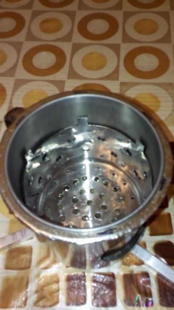
Several holes were made in the bottom of the furnace with a diameter of 8 mm for air flow from the turbine (Photo 4, 5).
The inner diameter of the support ring is somewhat (1 cm) smaller than the diameter of the furnace in the rim area. From the side of the inner diameter of this ring, radial cuts are cut through a length of 1 cm through 0.5 cm, and then bent 90 ° down, so that the firebox fits tightly into the support ring.
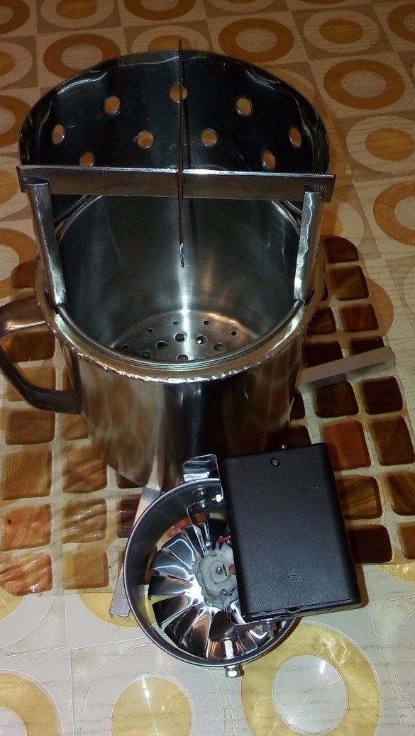
In order to prevent the furnace from falling through and not be able to bend the support ring under the weight of the dishes with food, a support disk in the form of a comb is inserted from the disk of a large tin can, which is inserted between the furnace and the inner surface of the bottom of the larger mug (Photo 5).
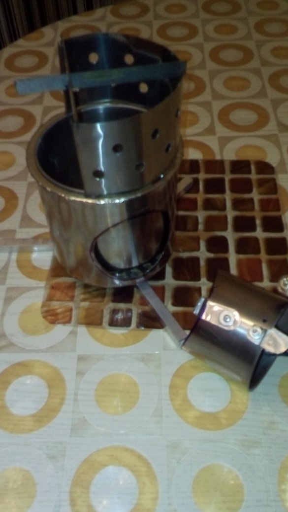
In the side of the larger mug for the turbine, opposite the handle, a hole is made equal to the diameter of the bottom of the turbine housing (Photo 4). A small horizontal cut was made in the upper part of this hole at a distance of 0.5 cm for attaching the turbine housing to a larger mug.
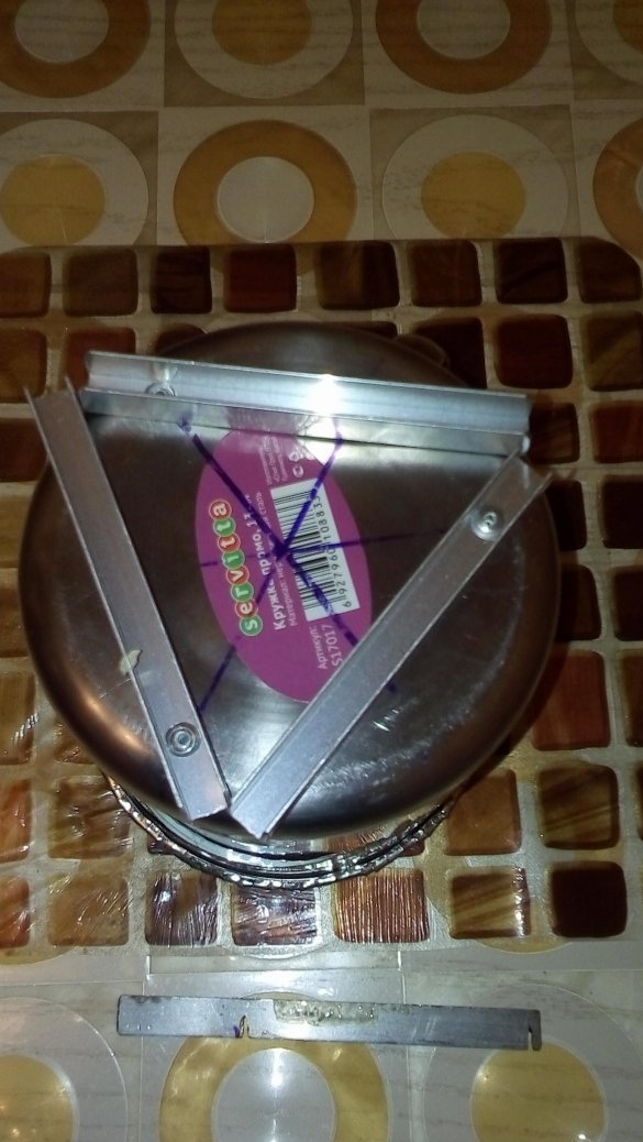
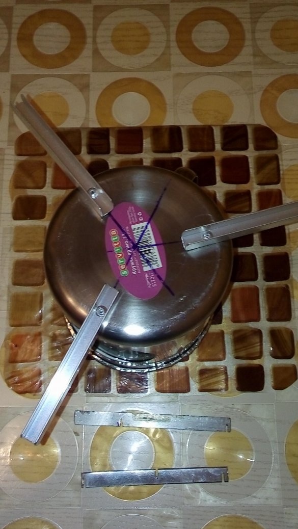
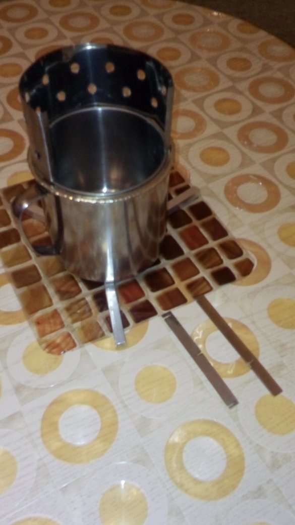
For greater stability of the entire furnace design, I installed at the bottom of a larger circle of rotary legs (deployed on steel rivets) that are riveted outside the bottom of the larger circle.
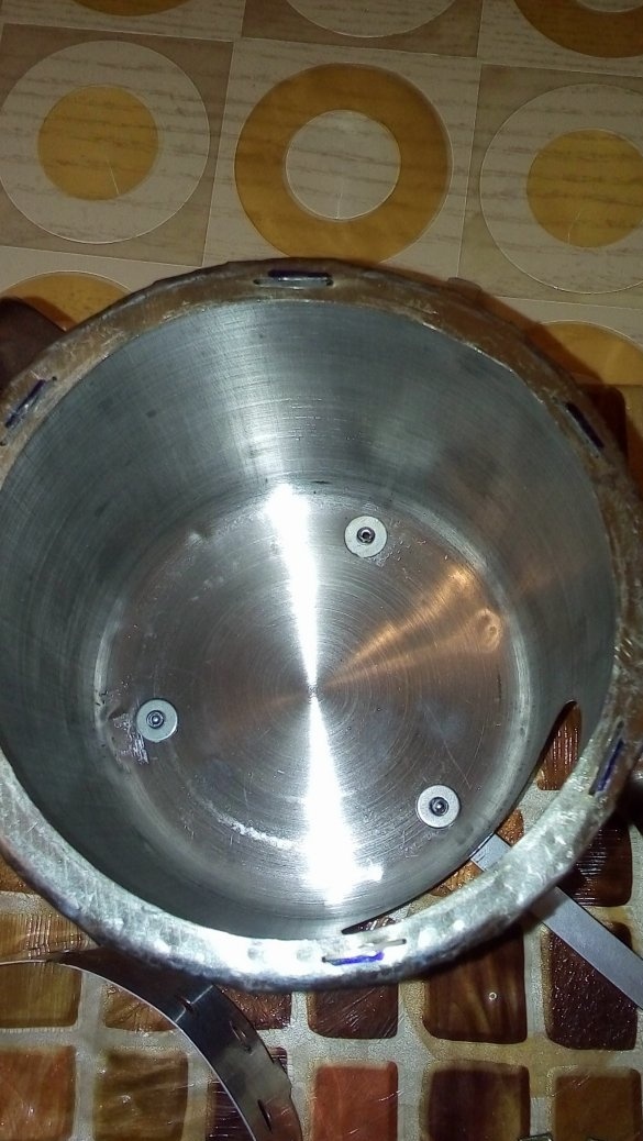
To do this, holes were made in the bottom of the larger circle with a diameter of 3.5 mm at an angle of 120 ° at a distance of 1.5 cm from the edge (Photo 6).
From a U-shaped aluminum 10 mm profile, I made three pieces 10 cm long, which will be uprights. They drilled 3.5 mm holes at a distance of 1.5 cm. Using steel rivets of 3.2 x 6 mm, these segments were fixed on the holes in the bottom of the larger mug.
In the transport position, the racks are folded, in the working position they are deployed (Photo 7.8).
In order for the furnace to be firmly installed in a large mug, I made a support ring from a sheet of thin stainless steel so that the edges of the ring protruded beyond the edges of the upper rim of the larger mug and it was possible to roll this protrusion onto this rim.
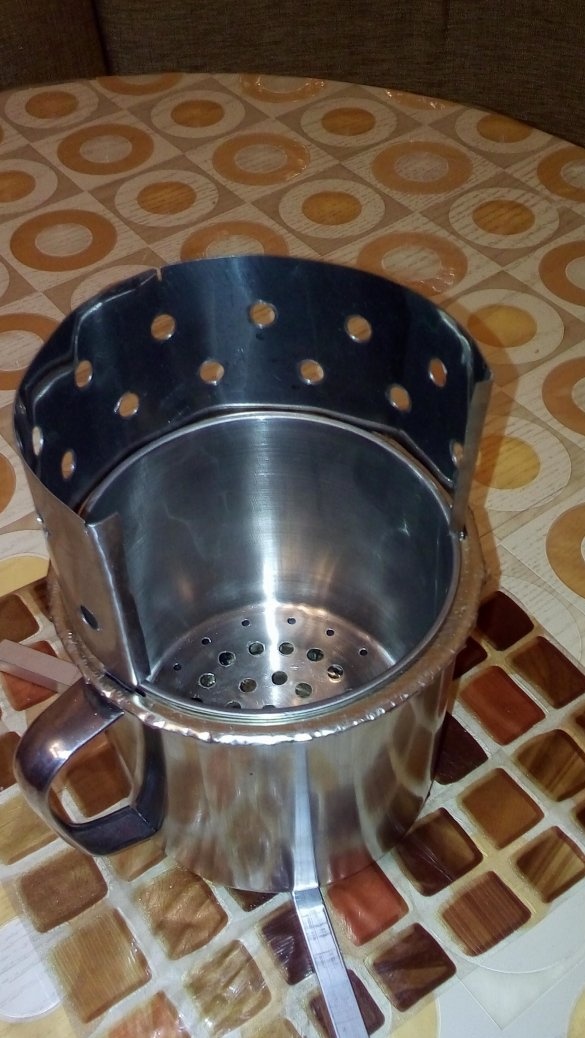
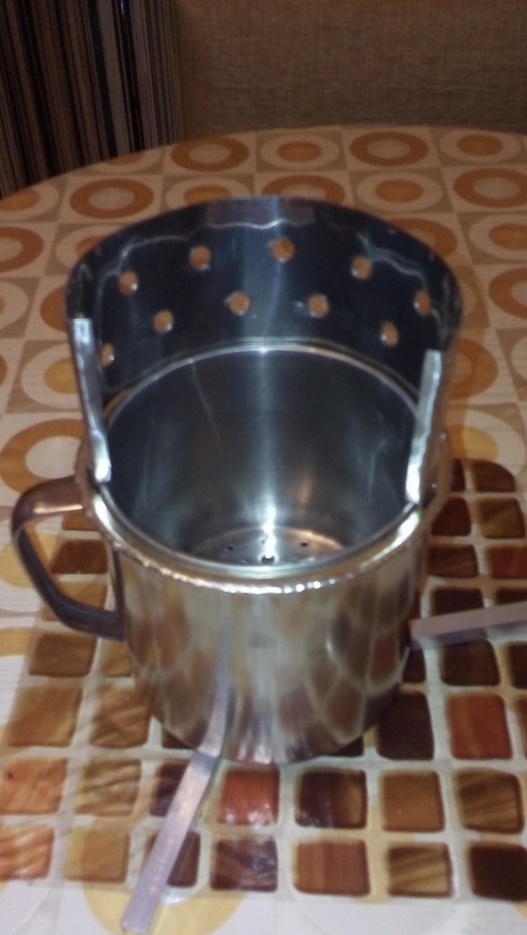
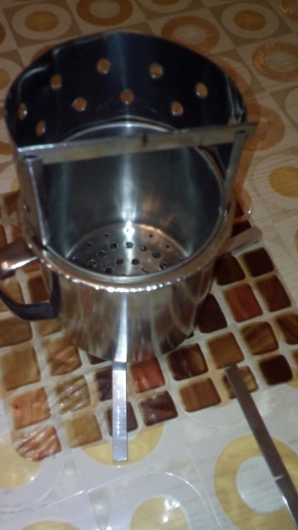
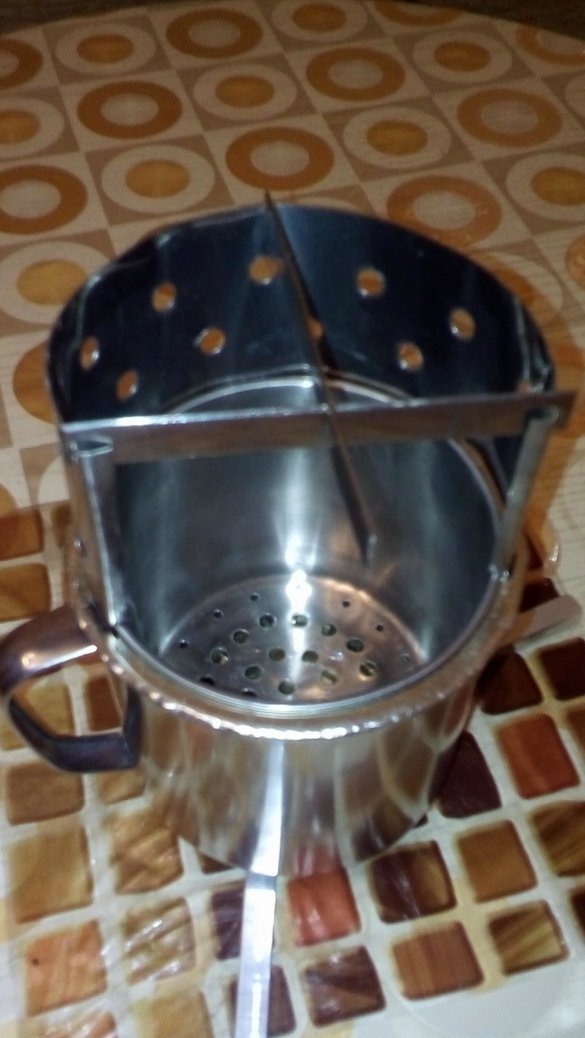
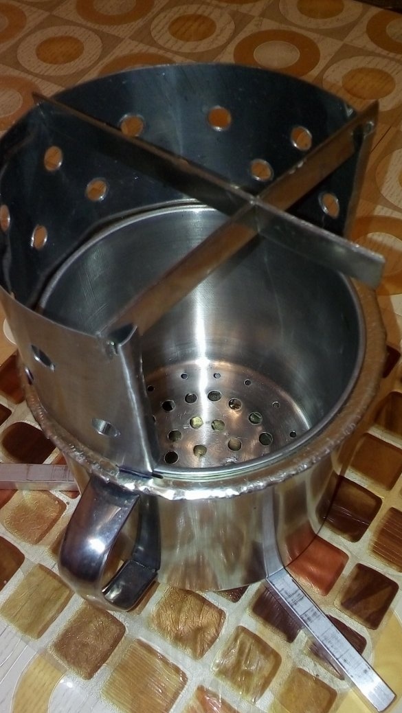
The furnace also includes an arched protective curtain made of a stainless steel strip 4 cm high and about 12-13 cm long (Photo 9-12).
Holes of 8 mm are made on this strip and projections 5-8 mm high are made in the lower part in the middle and from the edges at a distance of 5 mm. These protrusions allow you to securely fasten the protective curtain to the support ring. To do this, longitudinal cuts are made in the support ring in the appropriate places.
In order to ensure a reliable and safe installation of dishes on the oven, small and large support strips were made (Photo 12-15). The small supporting strip, which will be installed on the arc-shaped protective curtain and connect the ends of the arc, and the larger supporting strip, which will connect the middle of the arc-shaped protective plate and the small supporting strip, have small cuts that allow you to install the supporting bars and the arc-shaped protective curtain in the horizontal plane .
The smallest of the mugs is used as the turbine housing.
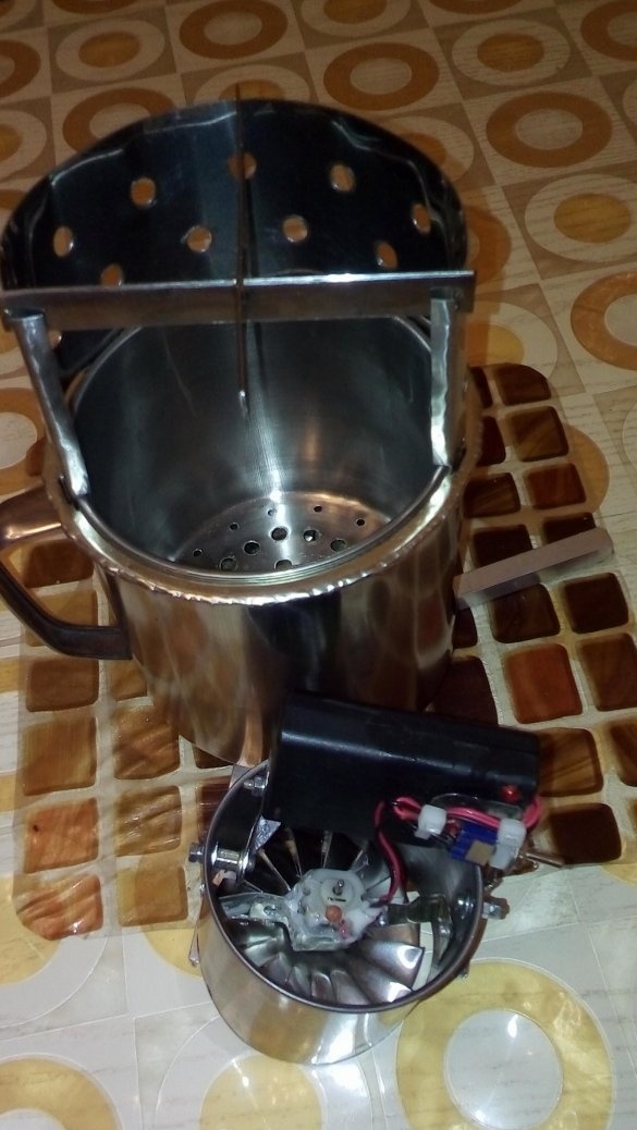
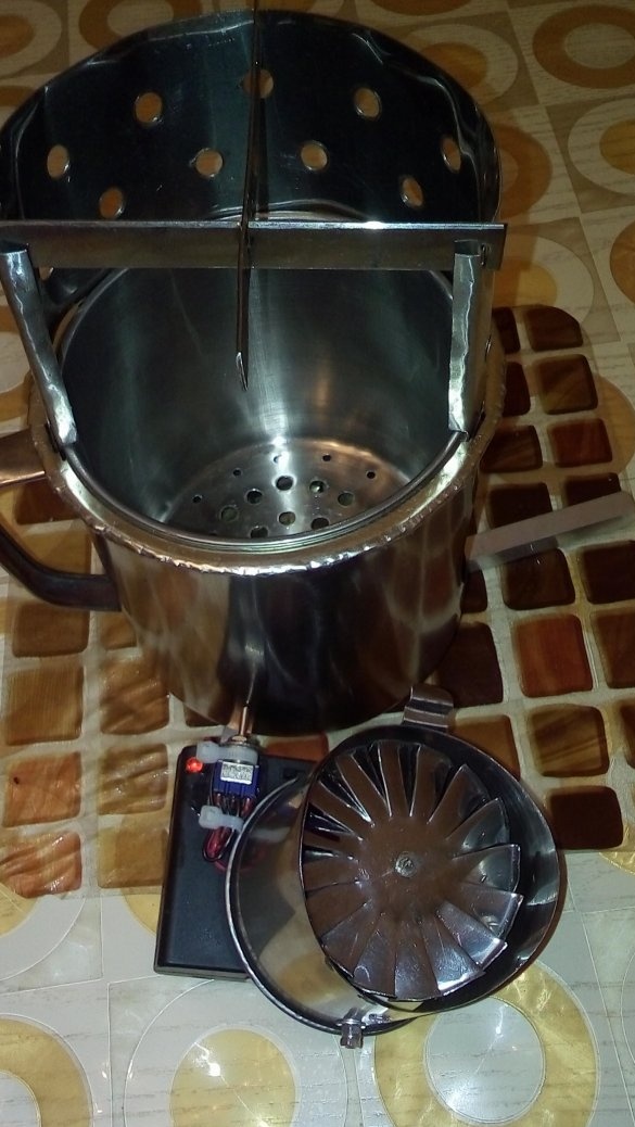
The turbine engine mounting units are installed in the turbine housing in such a way that the turbine fan is close enough to the housing of the larger circle, but does not touch it (Fig. 1, Photo 16-21).
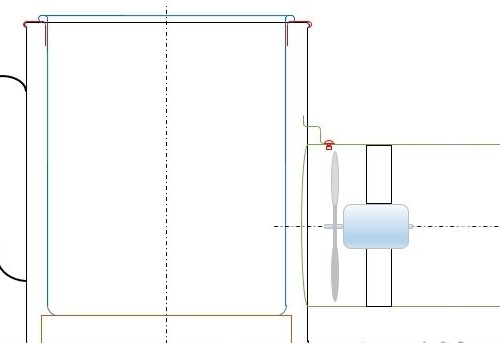
A bracket is mounted on the rivet in the upper part of the turbine casing (Fig. 1) for fastening a larger mug with a width of horizontal cut to the casing.
The engine is powered by a 3 and 4.5 V battery pack from AA batteries or rechargeable batteries. For this, a 3-position switch (toggle switch) is installed on the battery pack case (Photo 17-19). In neutral, engine power is off. In the upper position of the switch, 4.5 V is supplied, and in the lower - 3 V. This allows you to adjust the speed of the air flow of the turbine and thereby the temperature of the furnace.
For ease of use and greater airflow during turbine operation, the battery case is made on rotary nodes that rotate freely in the upper and lower parts of the turbine housing.
All elements of the furnace are conveniently stacked in the furnace (Photo 21-22).
A similar design was tested on a trip to Shumak in 2017. It has proved extremely good. Firewood consumption is minimal. Almost everything was cooked on the stove.
Thanks for attention.
All the best.

