
The essence of this project, implemented by an electronics student, is to combine a power source in one Arduino case for portable use. Those. On this platform, it will be possible to test any ideas and technical solutions related to Arduino.
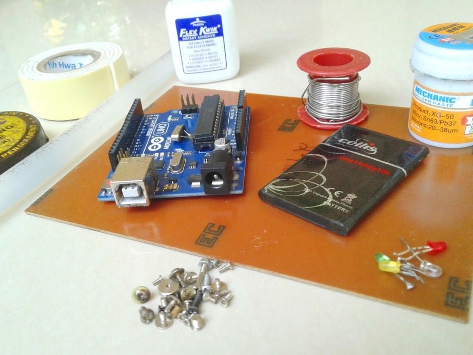
Tools and materials;
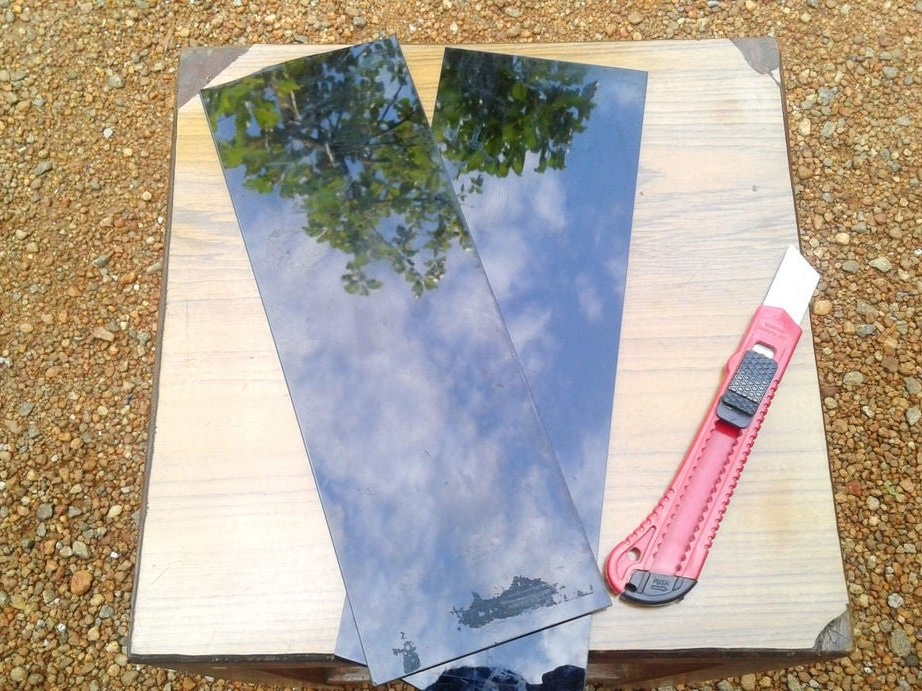
-Black acrylic;
-Electronic Components;
-Lithium-ion battery;
-Wire;
-Soldering accessories;
-Glue;
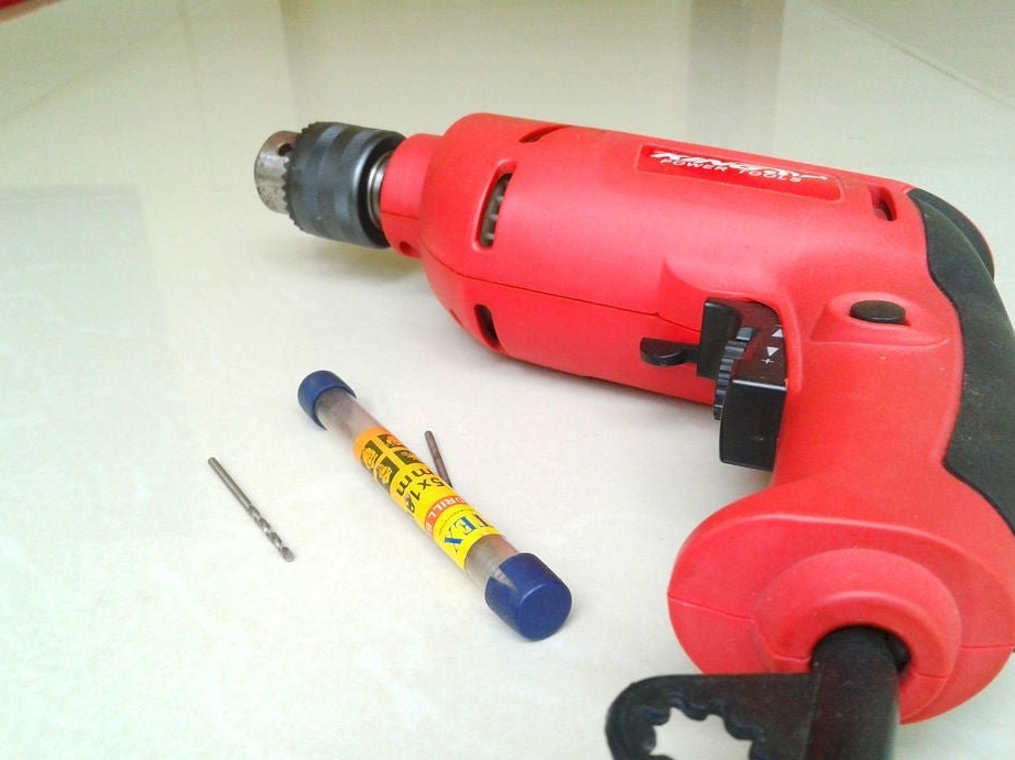
-Drill;
-Fasteners;
-Double sided tape;
-Scissors;
-Rule;
-Marker;
-Hole puncher;
-Pliers;
-Screwdriver;
-Hacksaw;
-Tweezers;
-Nadfiles;
-Iron;
- A plate with a copper coating for printed circuit boards;
-Laser printer;
- iron chloride;

Step One: Project
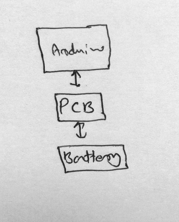
As conceived by the master, Arduino and a lithium-ion battery should be placed in an acrylic case. The battery has a voltage of 3.7 V, which means a boost module is needed. You also need a charge module and an indication of the charge and discharge of the battery.


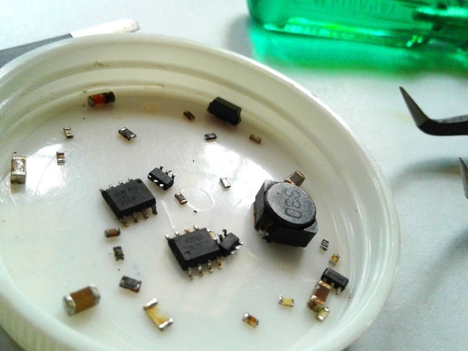
For the manufacture of electronic circuit boards, the master uses secondary SMD components extracted from unnecessary electronics. Below you can watch a video with examples of dismantling SMD components.
The wizard does not list the necessary details, referring to the fact that everything is indicated on the diagram.
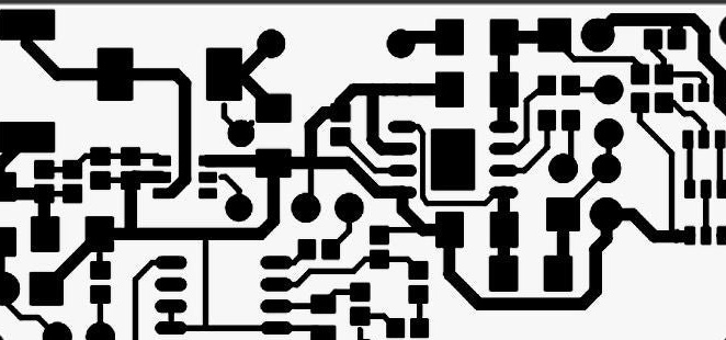
Step Two: Scheme
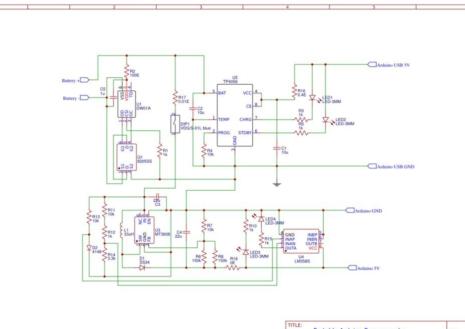
The circuit diagram is developed in EasyEDA software.
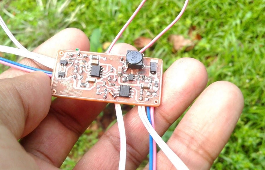
The first part is a battery protection circuit containing the IC DW01 and one MOSFET IC 8205SS. It is used for short circuit protection, overcharge protection and deep discharge protection.
The second part is the battery charging circuit. The lithium-ion battery needs special care to charge. This TP4056 Charger safely controls the charging process. The charging current is fixed at 120 mA, and it stops the charging process when it reaches 4.2 V. Two LEDs are also installed to inform about a discharged battery and the end of charge.
The third part is a battery discharge indication circuit. It is designed by connecting the LM358 operational amplifier as a comparator.
The last part is a 5V boost converter. You need to increase the battery voltage of 3.7 V to 5 V for power Arduino.
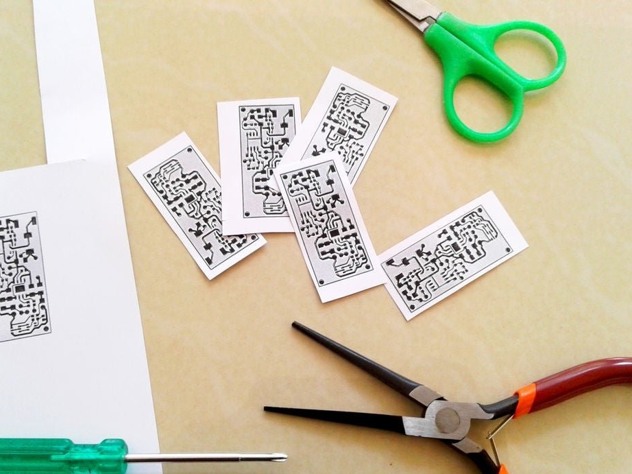
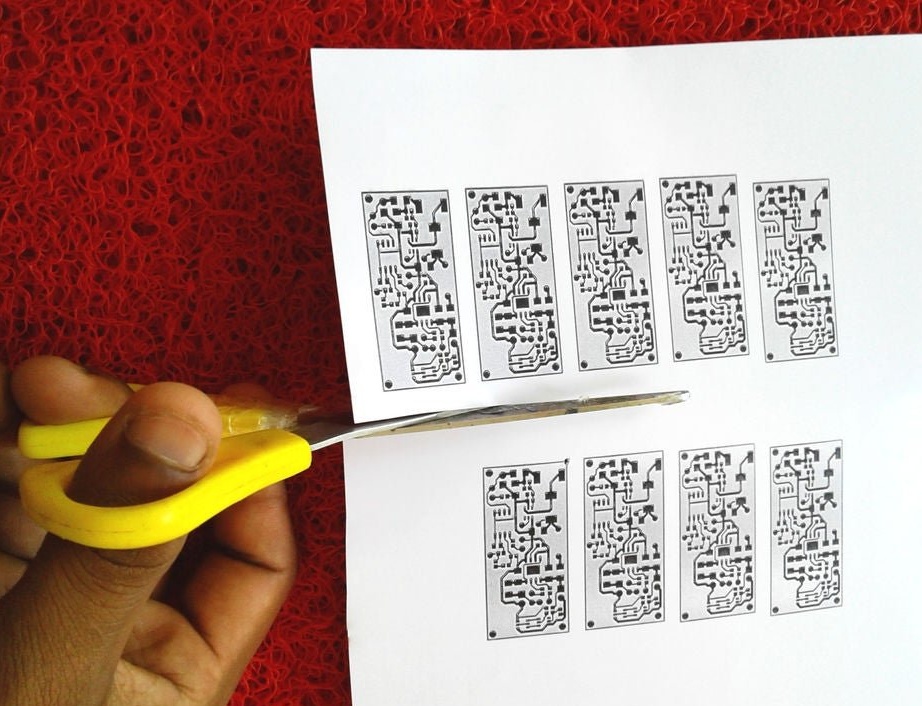
The master prints a printed circuit board layout on glossy paper (photo paper) using a laser printer.

New Microsoft Word.pdf
Gerber_portable arduino pcb_20190413104015.zip
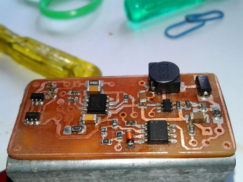
Step Three: Making the Board
Next, you need to make a printed circuit board.
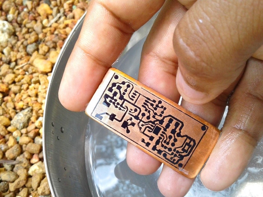
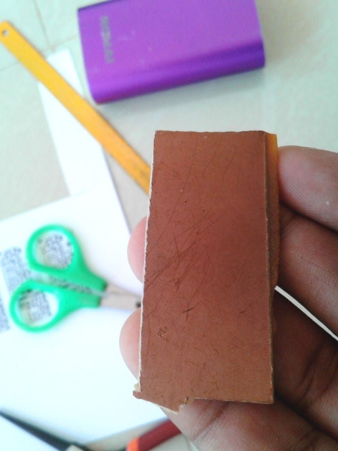
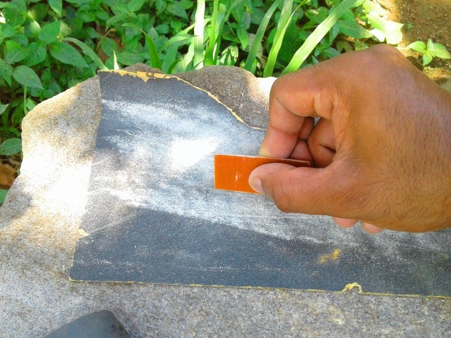
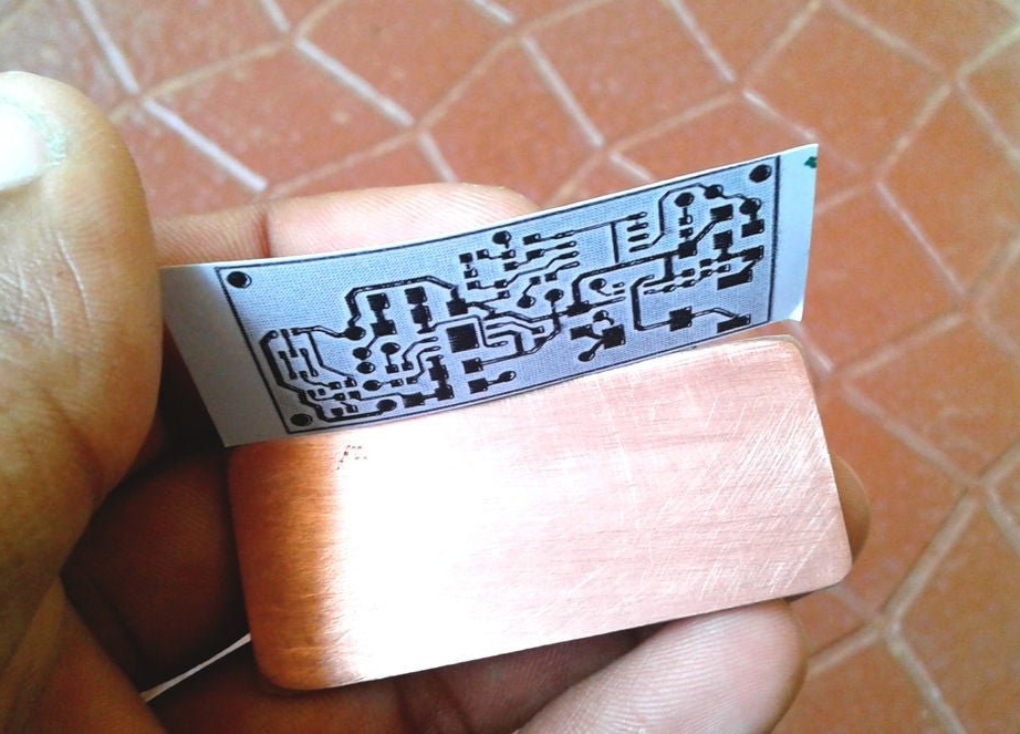
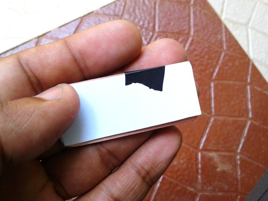
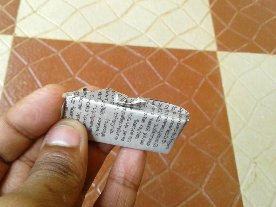
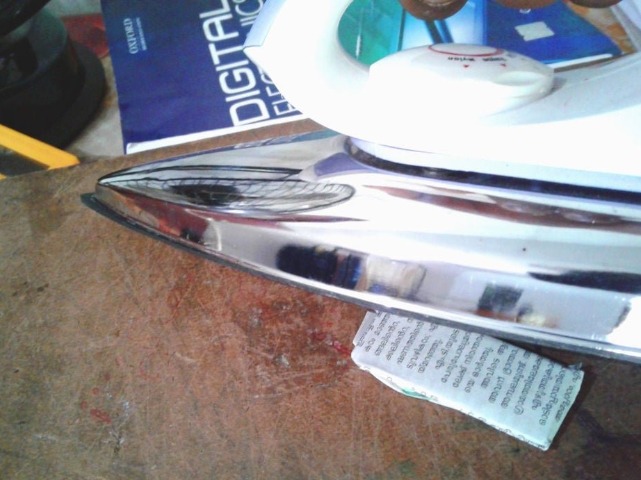
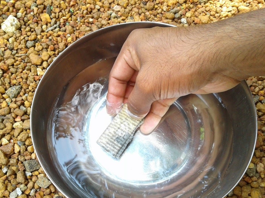
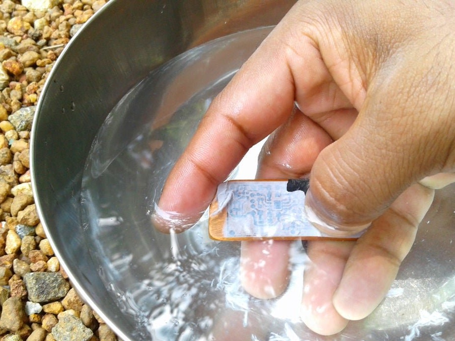
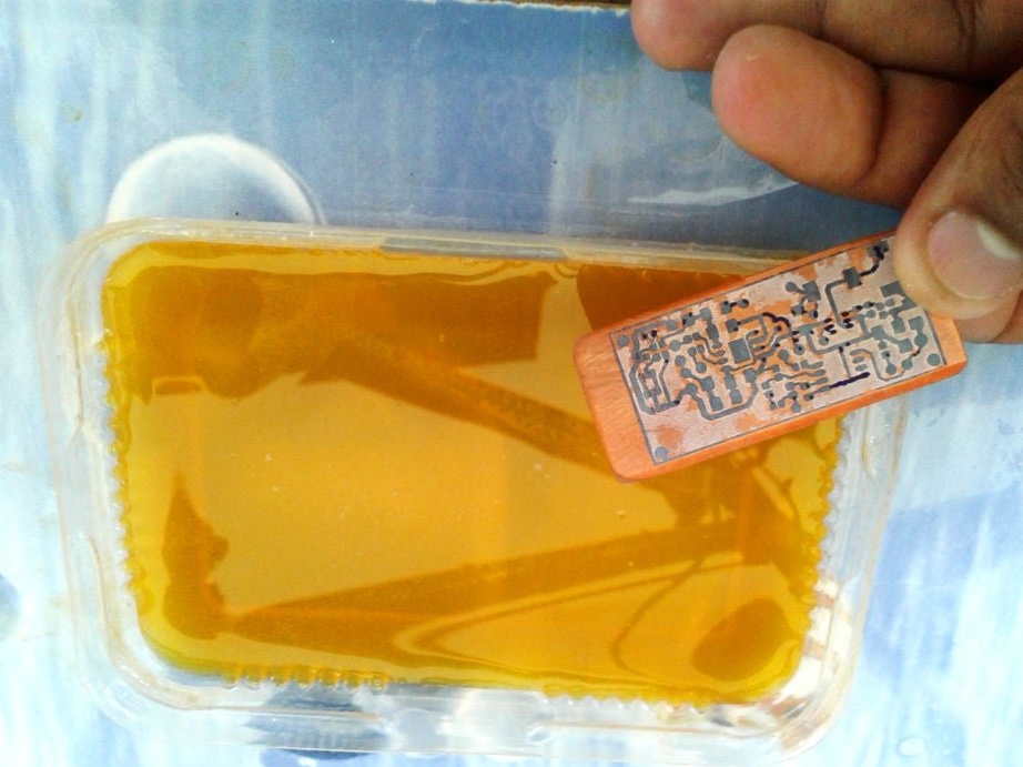
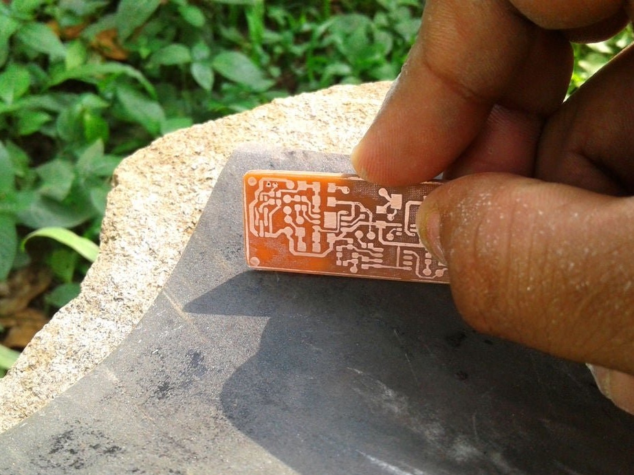
Cut the plate to the desired size. The copper layer must be lightly peeled. Then, a printed circuit board layout is attached to the copper layer.The blank is wrapped in a newspaper sheet and heated with an iron for 15-20 minutes. Then the blank is placed in water, and the paper is removed. The photo shows that the toner is fixed on the copper layer of the board.

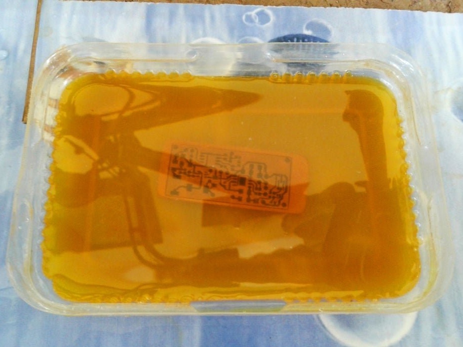
Now you need to remove the copper around the tracks. To do this, the board must be etched in the etching solution.
Iron chloride is diluted in a container of water. Etching time depends on the saturation of the solution, but a highly saturated solution can damage the tracks. The master recommends a solution with an average concentration of iron chloride.
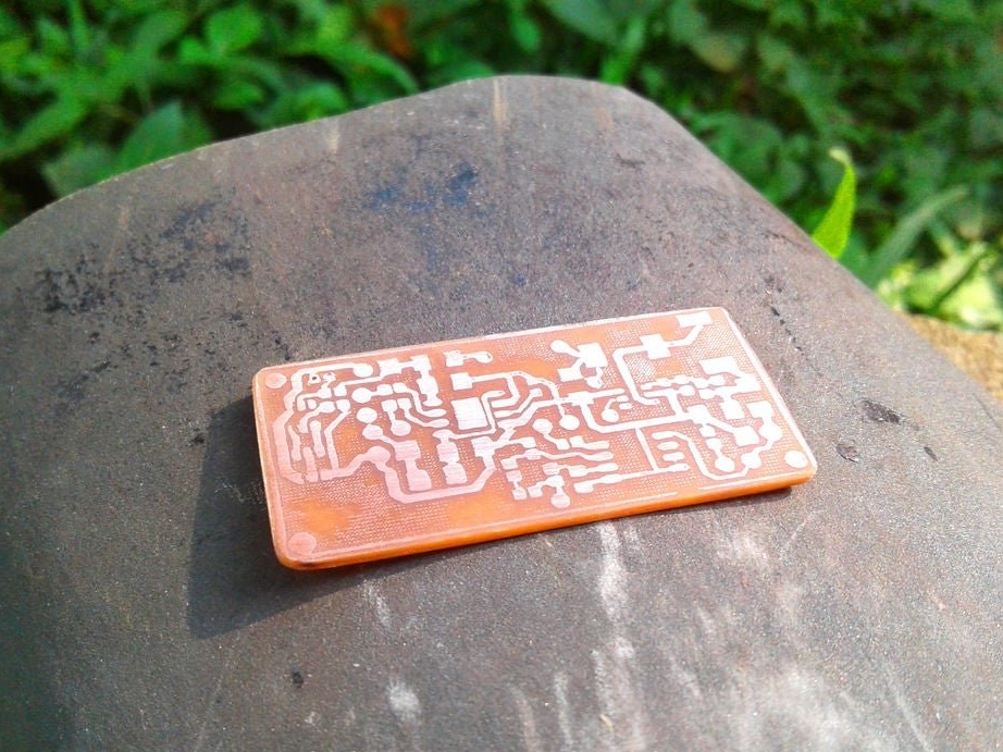
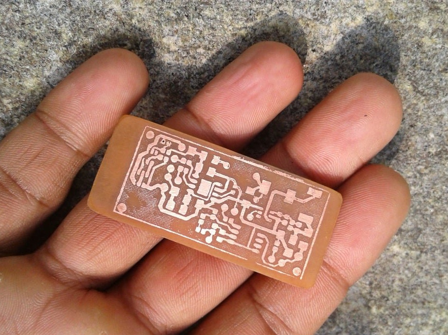
A board is placed in the solution container. Periodically, the container must be shaken, and the solution mixed. After a certain period of time, the solution will corrode the copper coating around the tracks. As soon as this happens, the board is removed and washed. Then you need to erase the toner from the tracks with sandpaper.
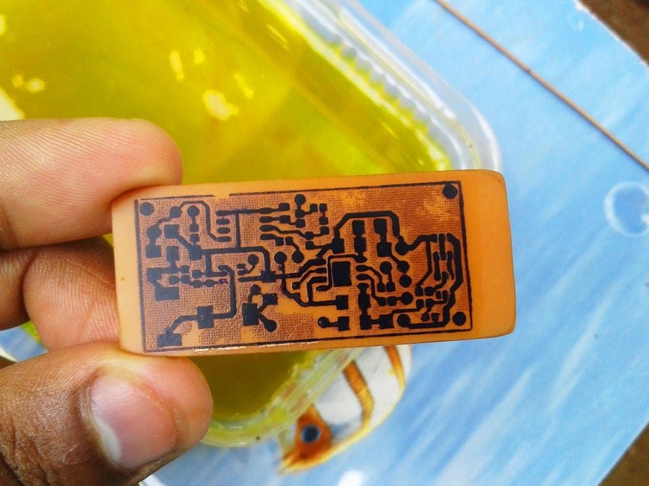
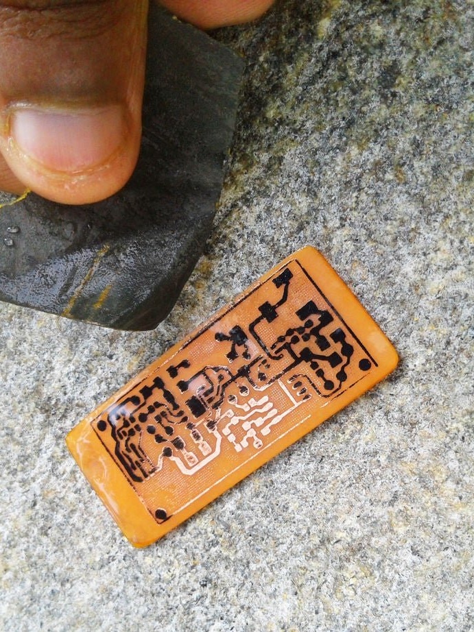
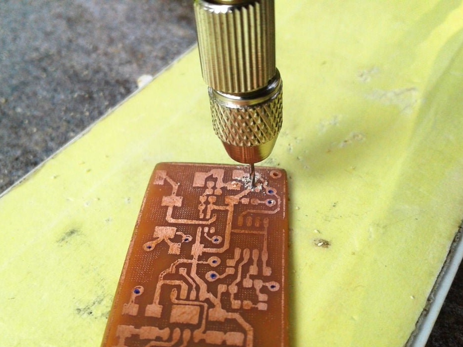
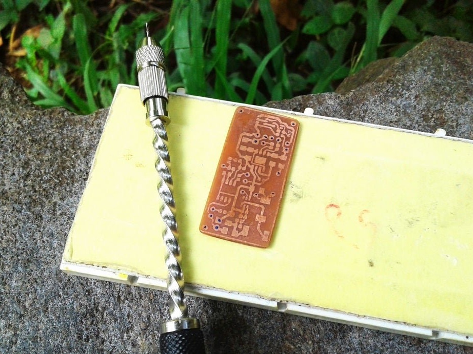
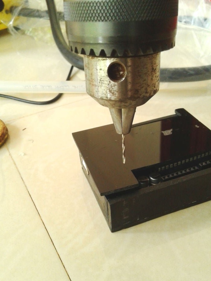
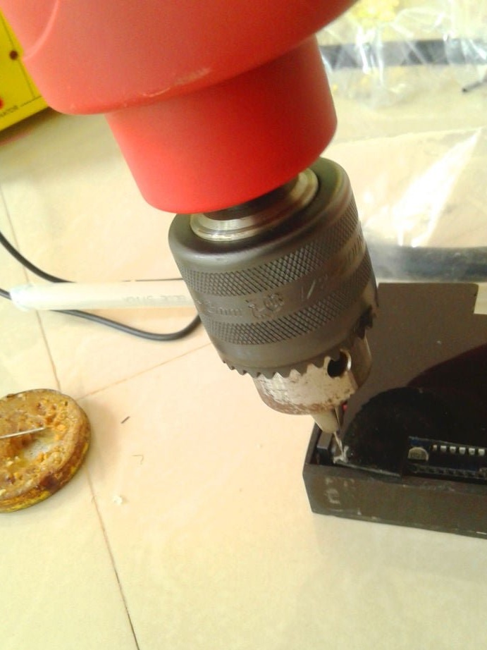
Now you need to drill holes and the circuit board is ready.

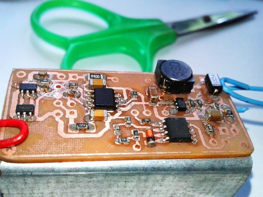
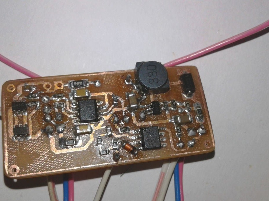
Step Four: Installing the Board
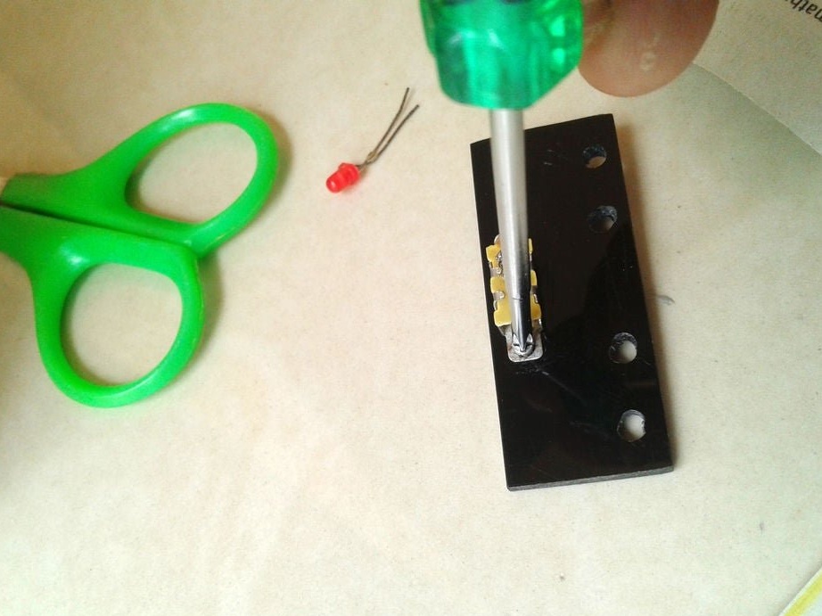
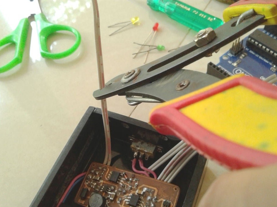
Now you can proceed to installation according to the diagram.
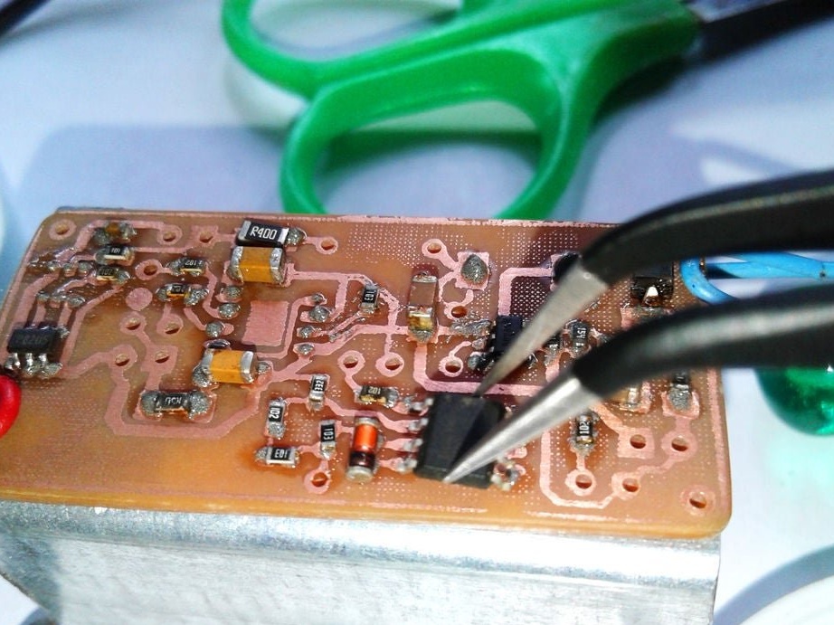
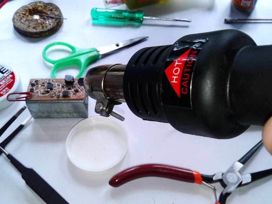

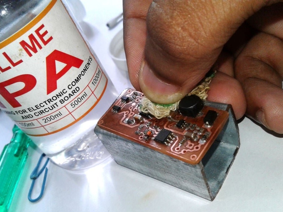
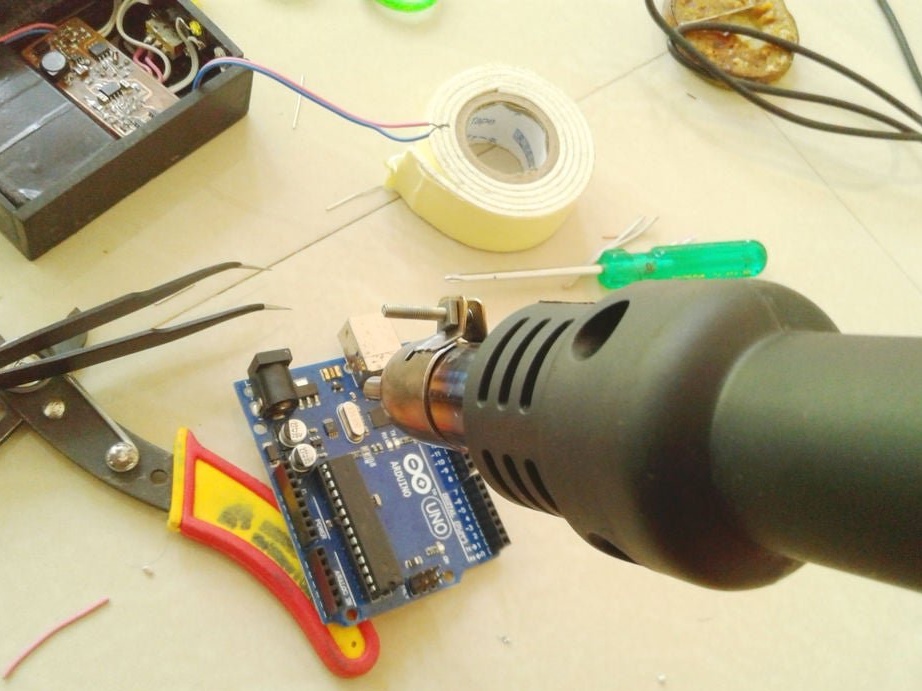
Soldering SMD components is a bit more difficult than soldering. The master shot a whole video with instructions on the basics of such soldering.
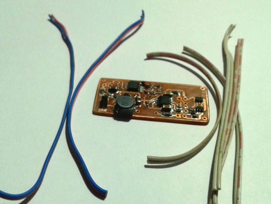
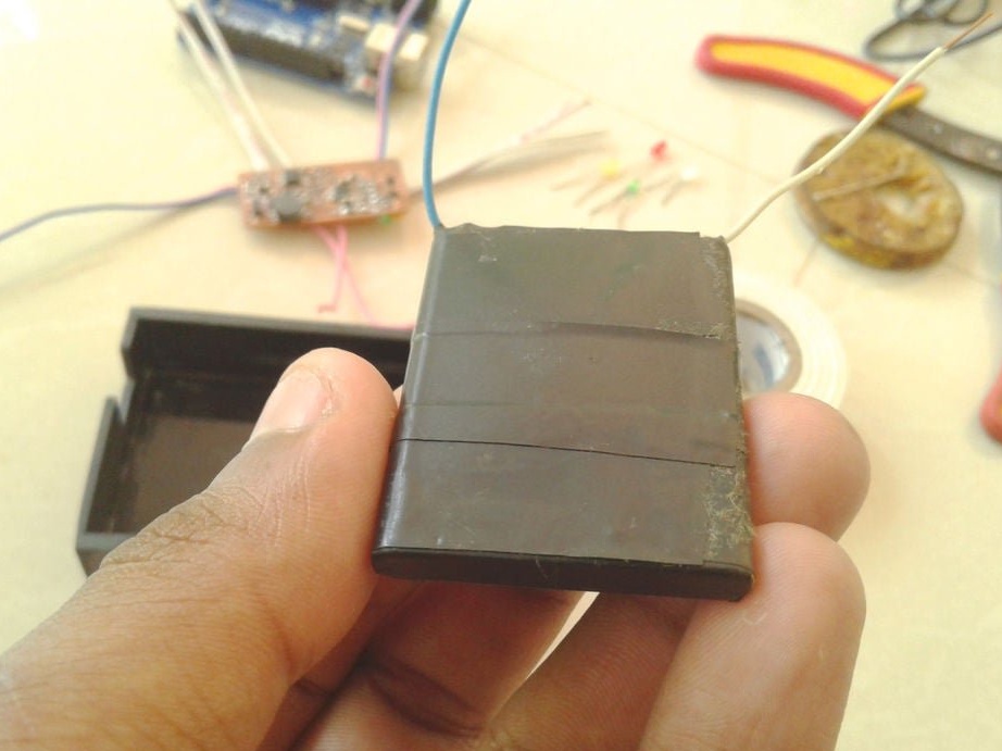
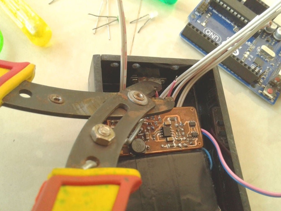
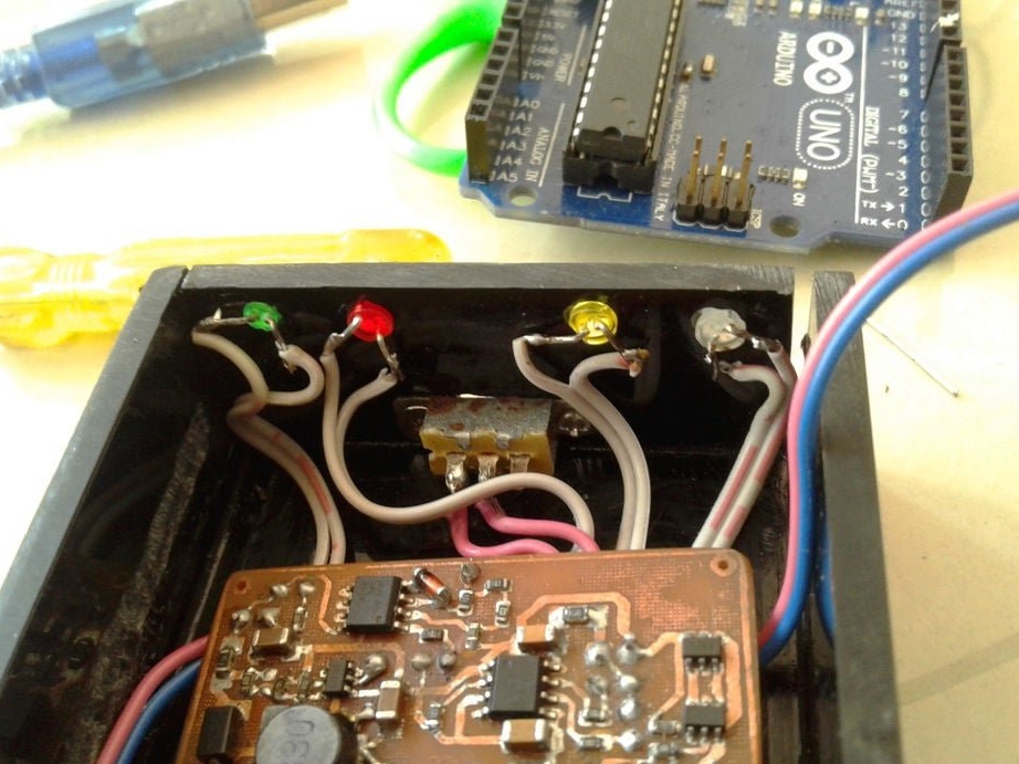
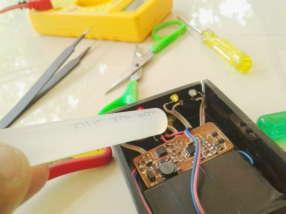
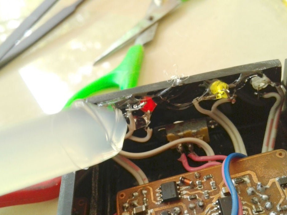
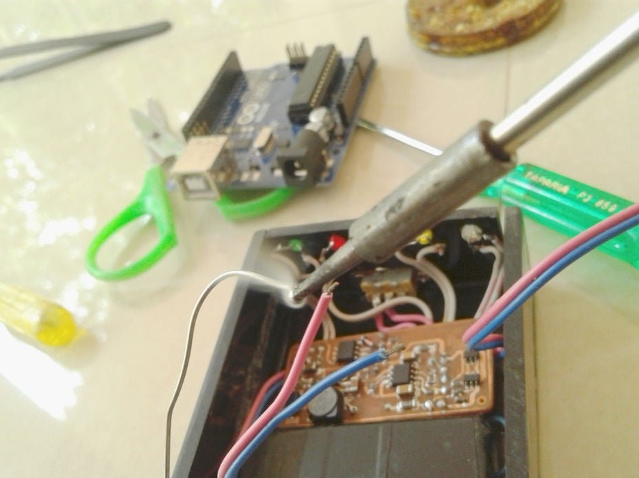
After mounting the parts, it remains to solder the wires for the LEDs, batteries, etc. It is advisable to use wires of different color markings.


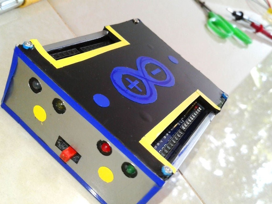
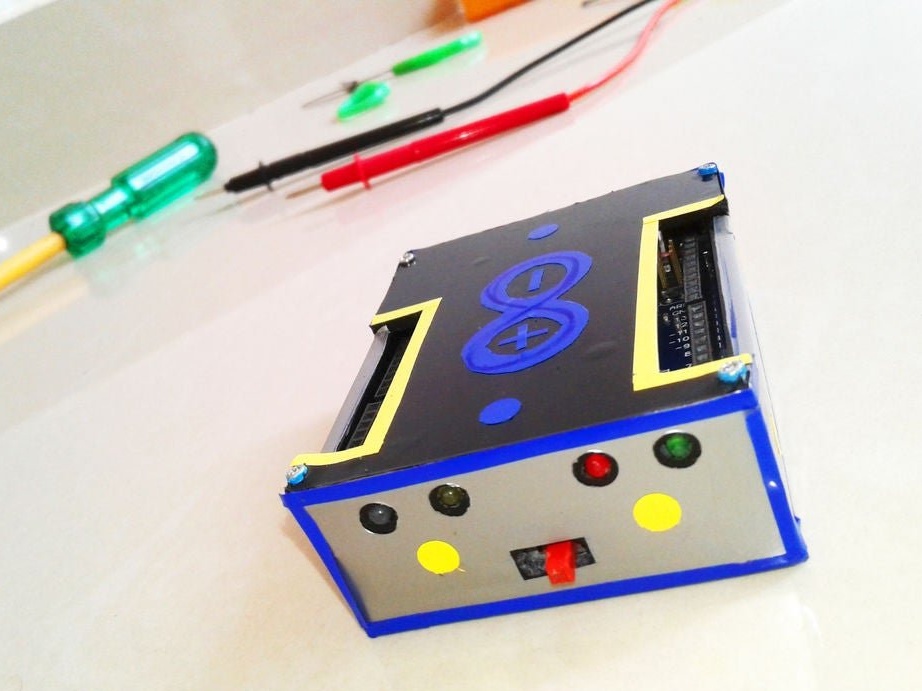
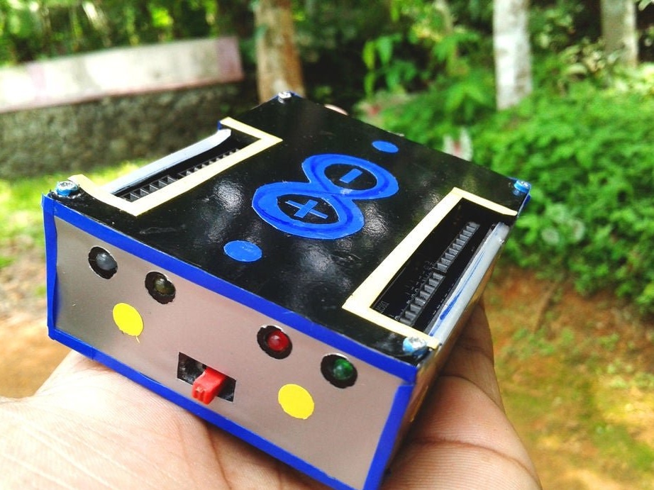
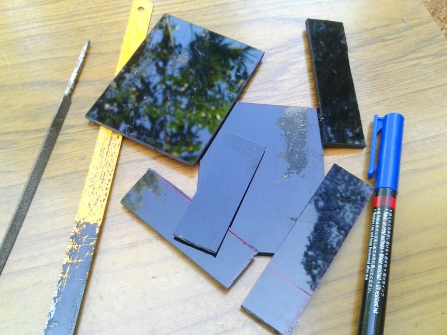
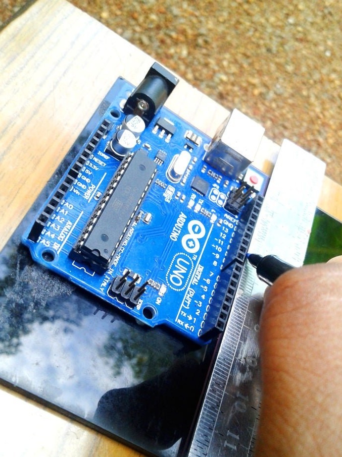
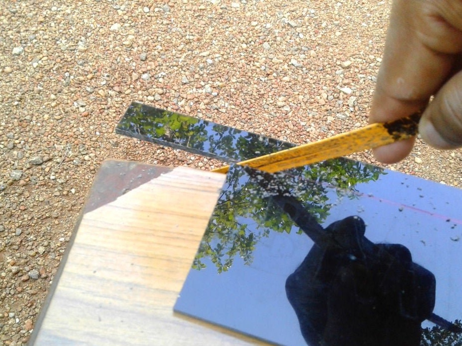
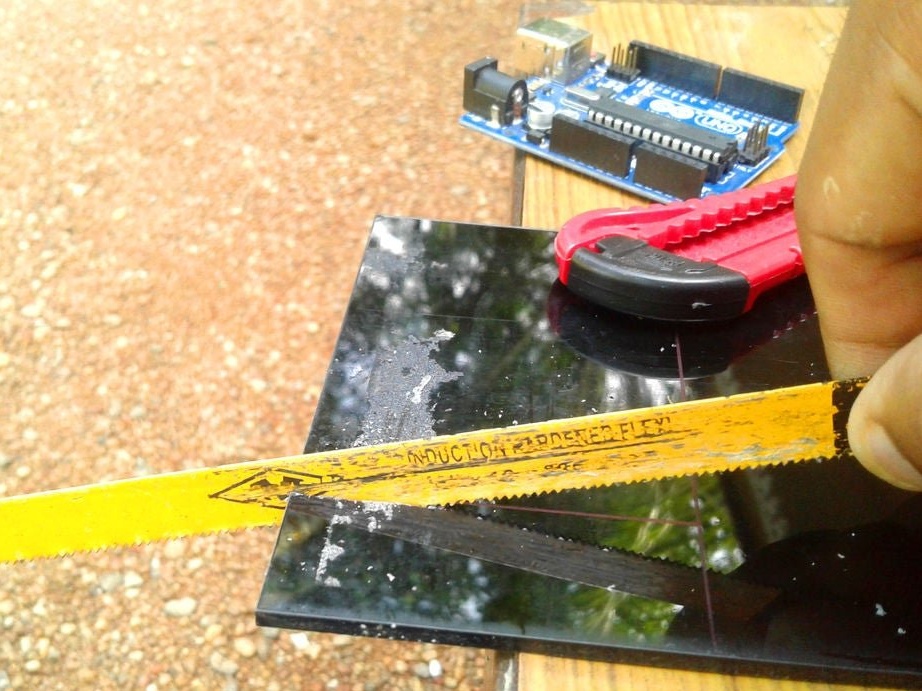
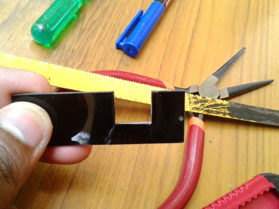
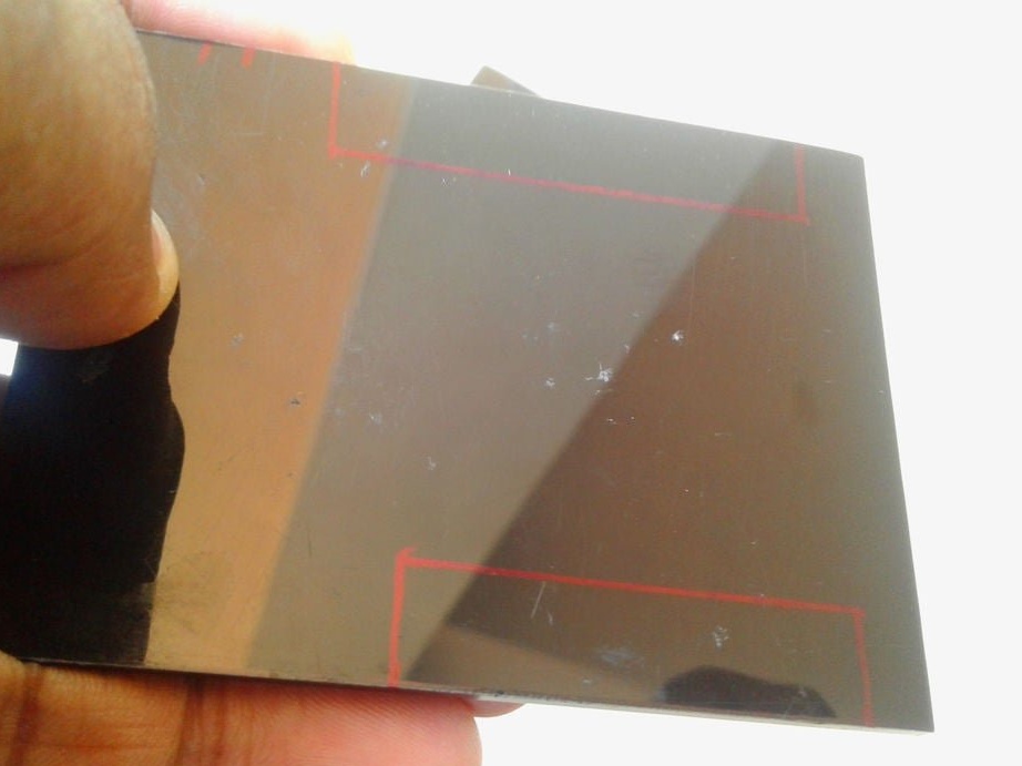
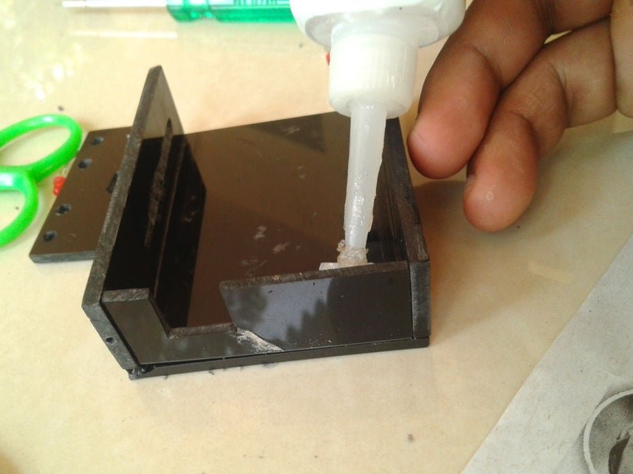
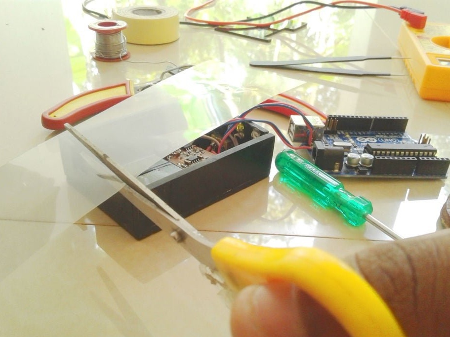
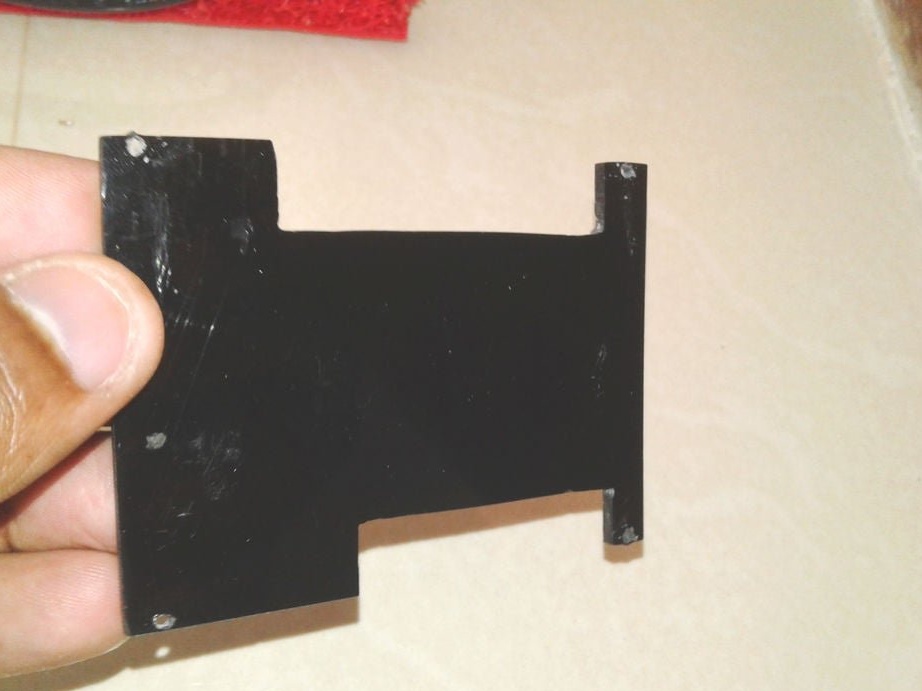
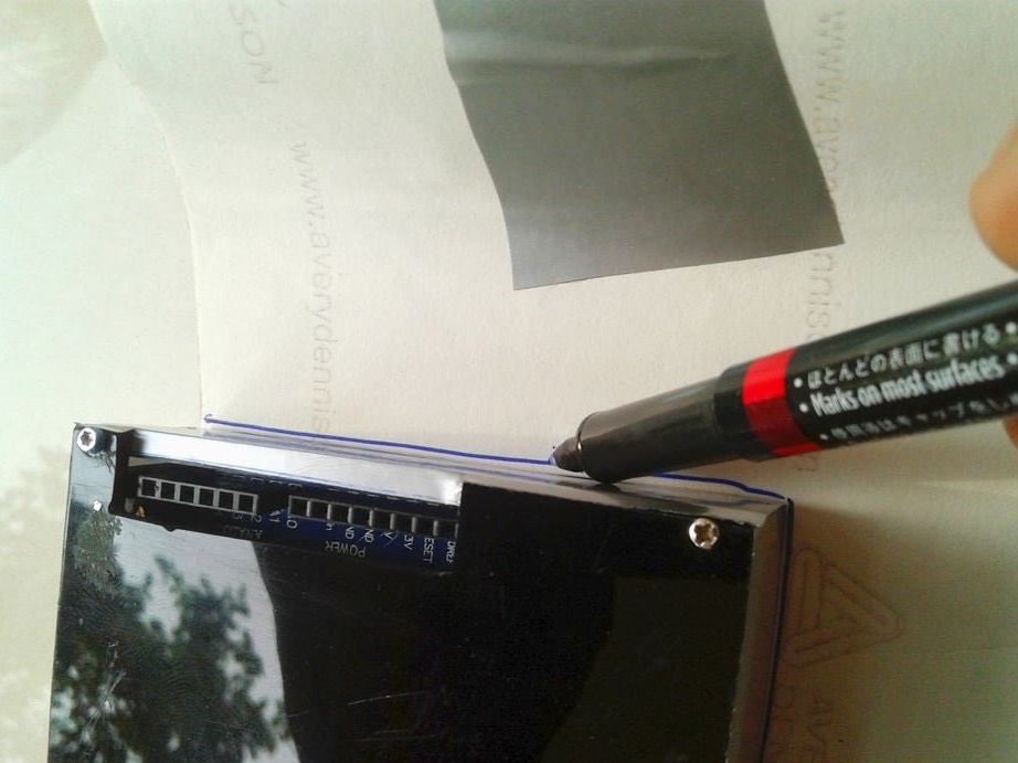
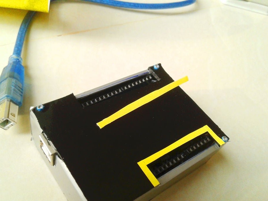
Step Five: Making the Case
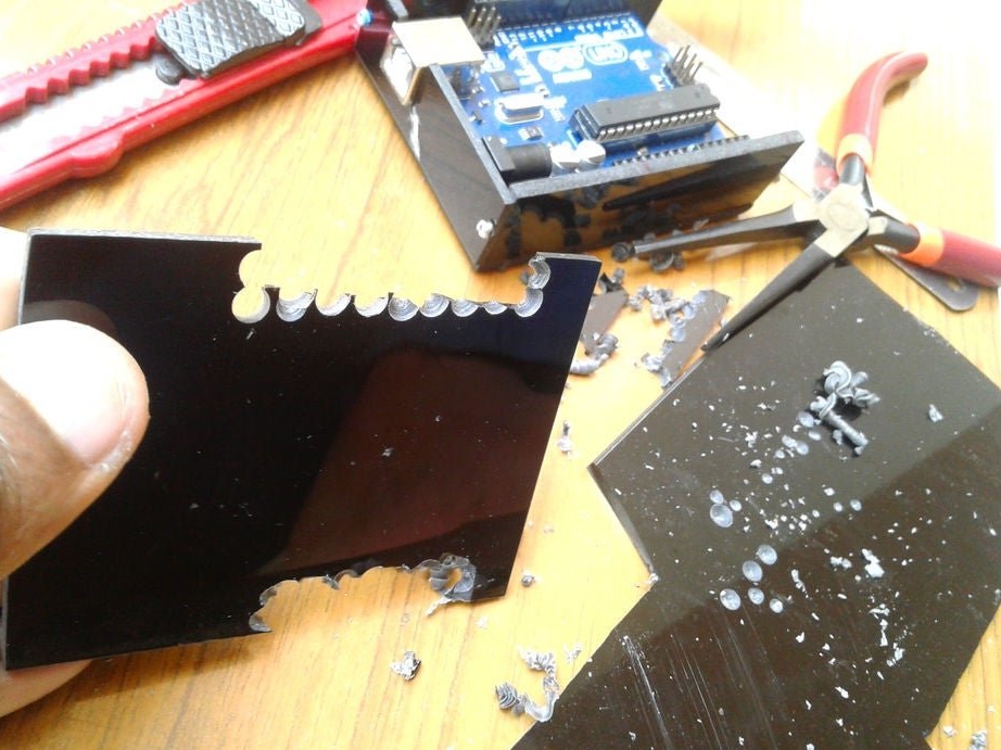
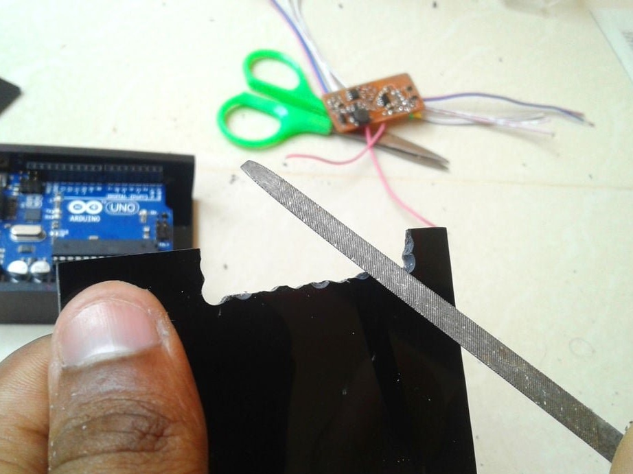
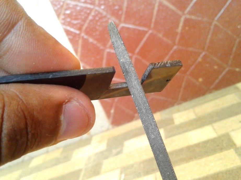
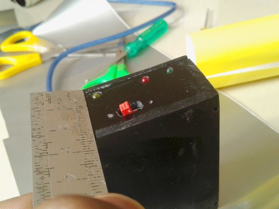
The case is slightly larger than the Arduino. The battery and board will be installed under Arduino. The master marks and cuts out the details of the body from acrylic.
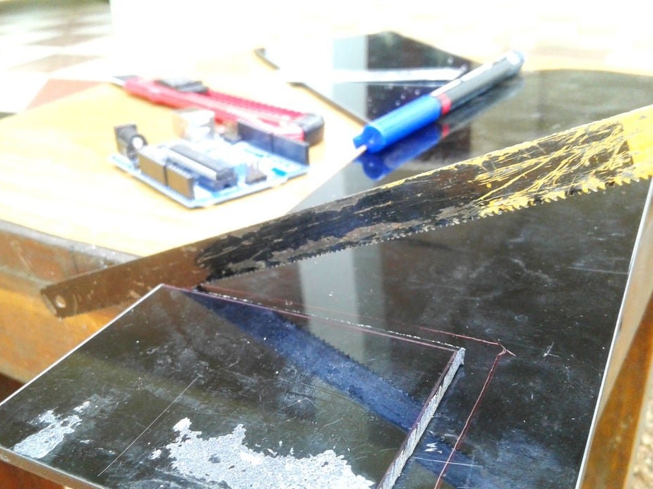
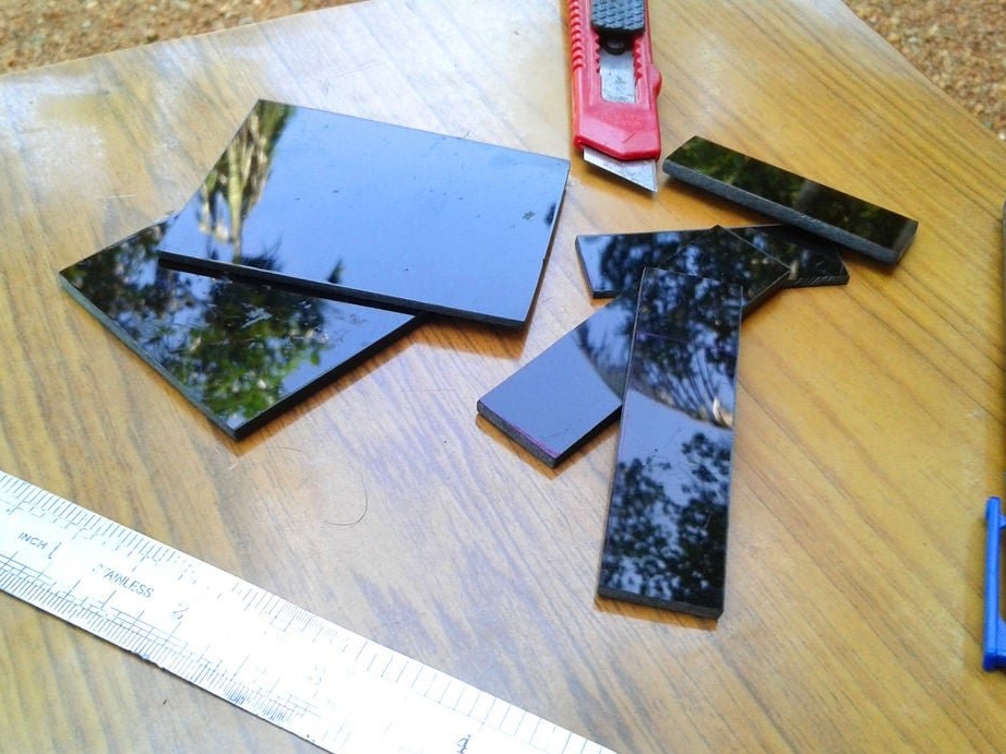
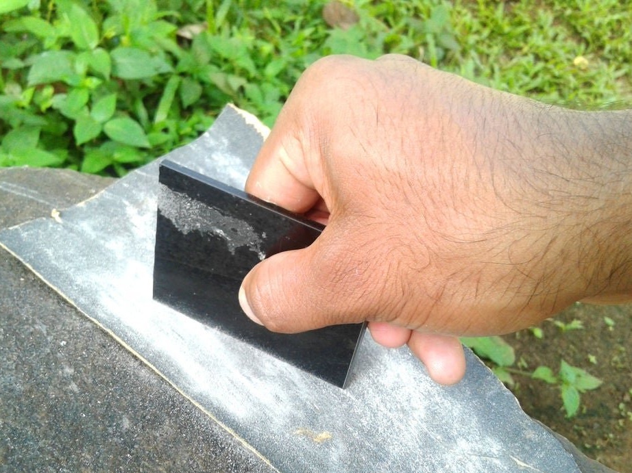
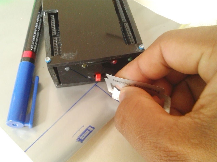
Cleans the edges with sandpaper.

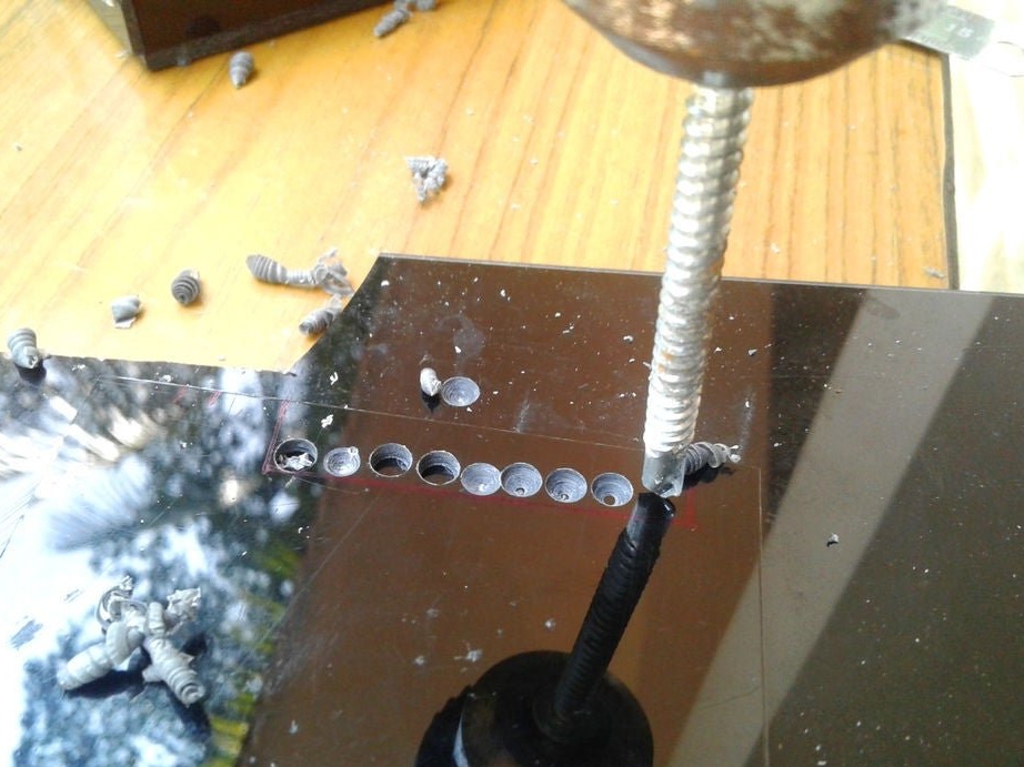
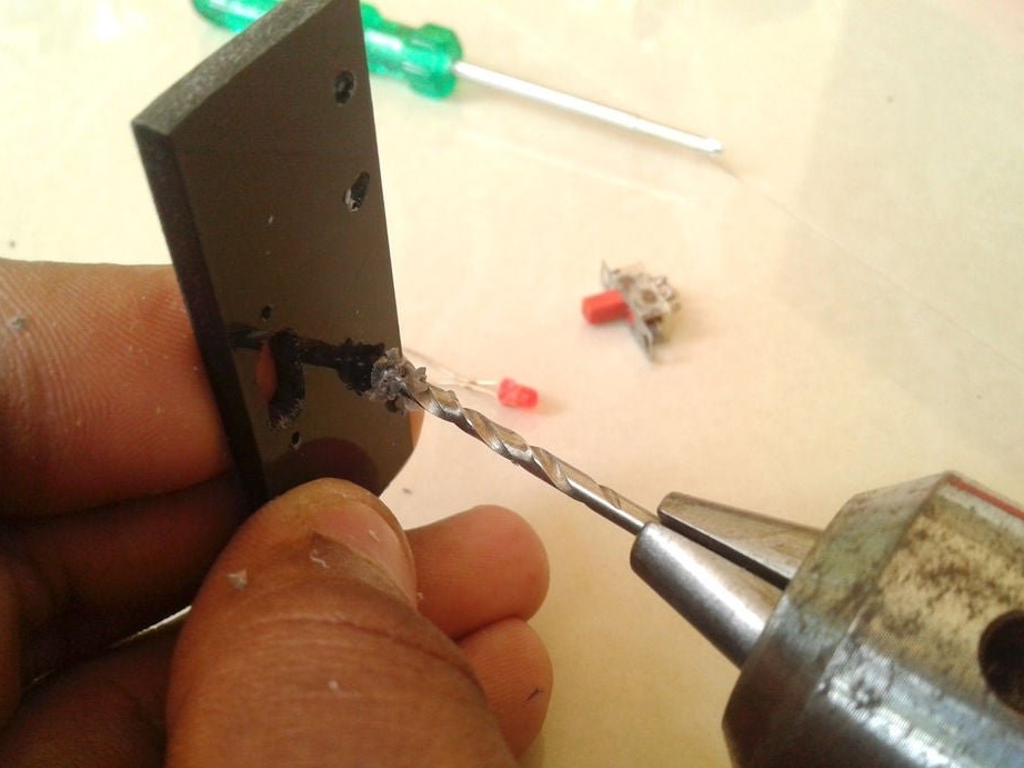
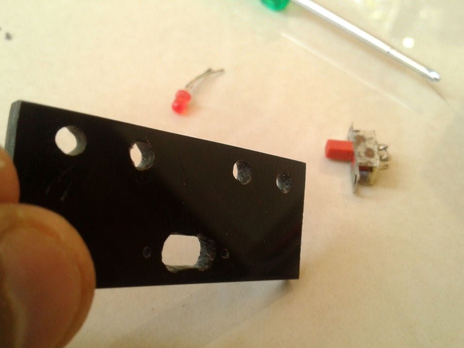
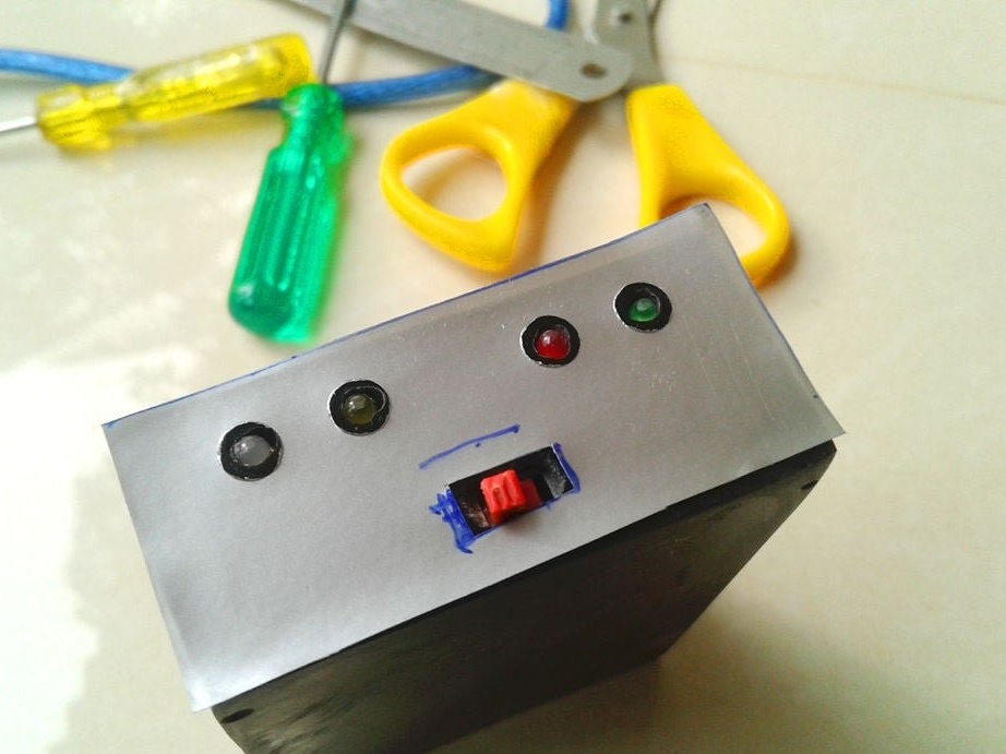
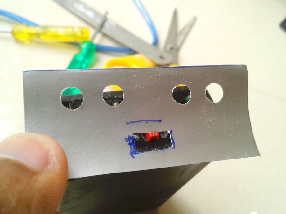
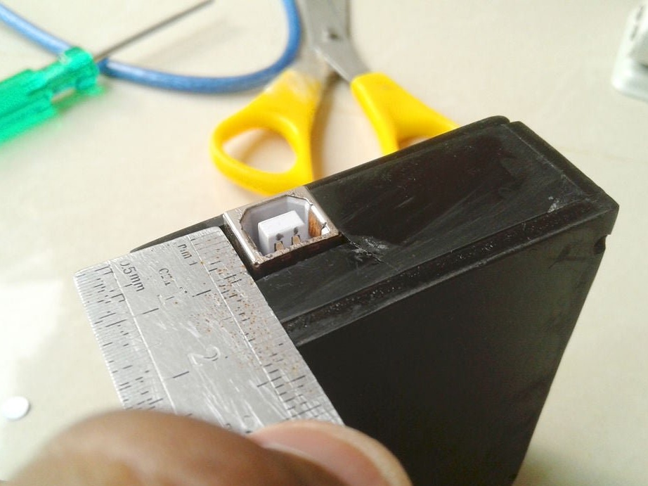
Cut technological holes.


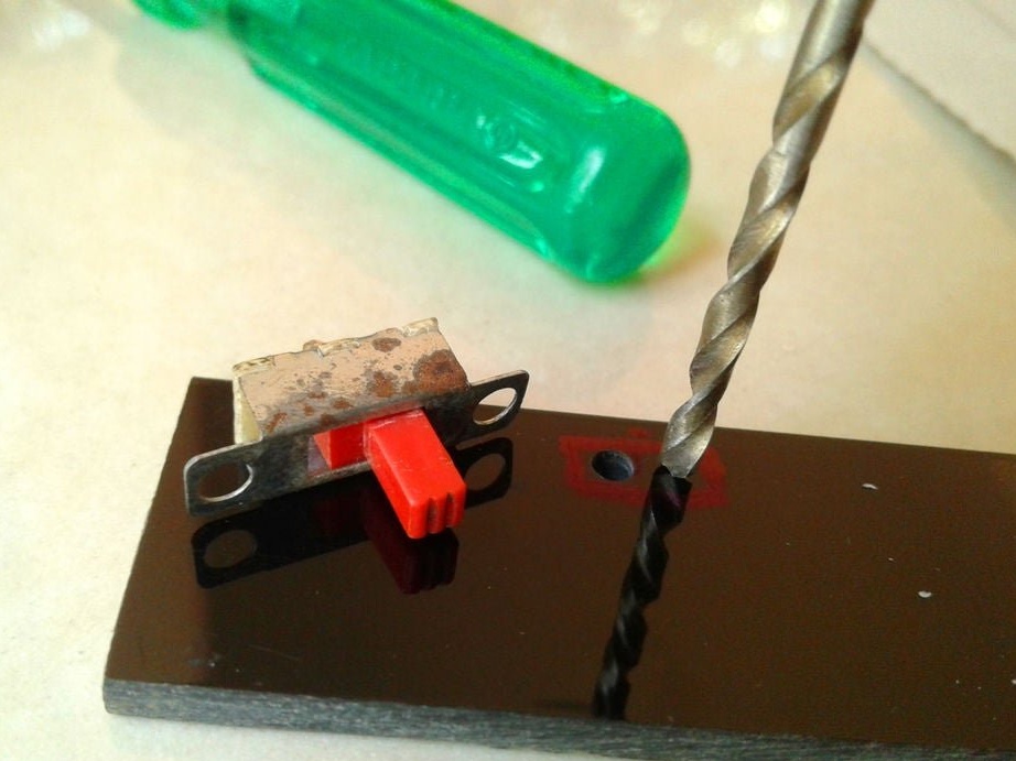
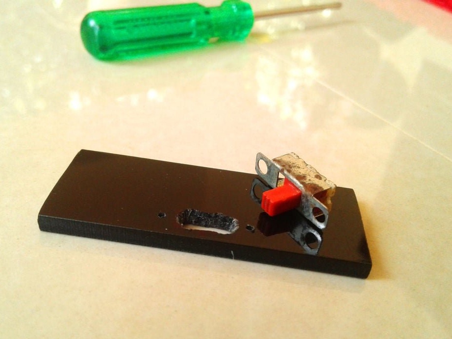
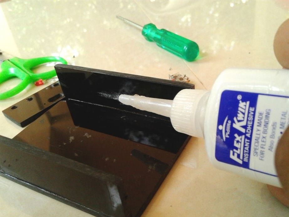
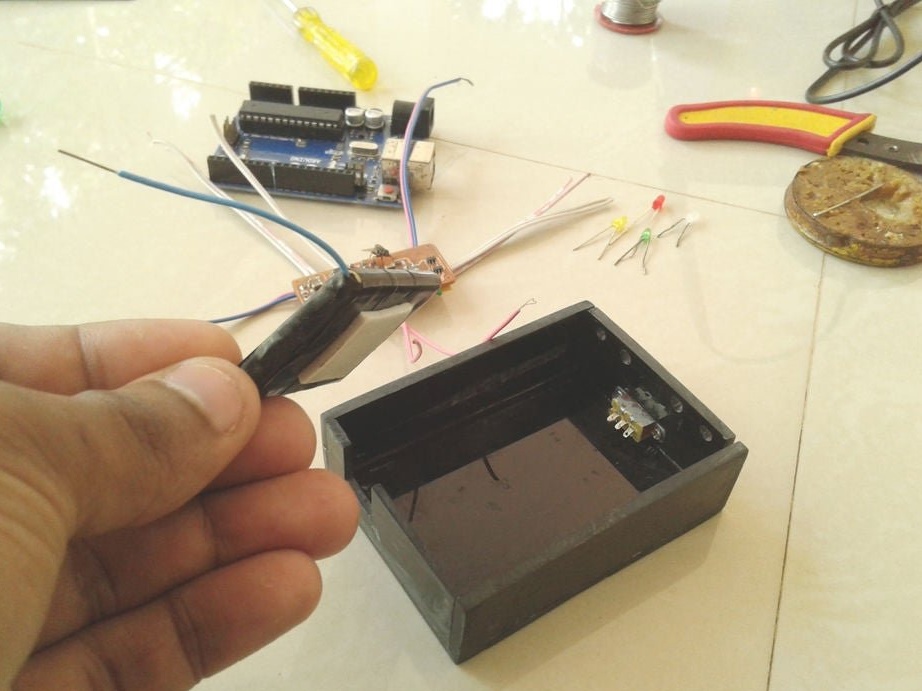
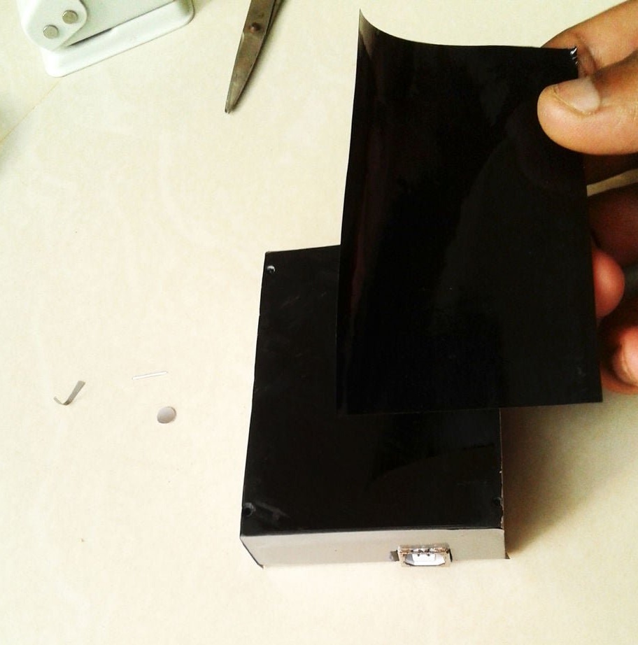
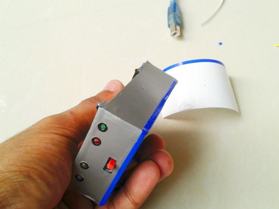
Step Six: Build
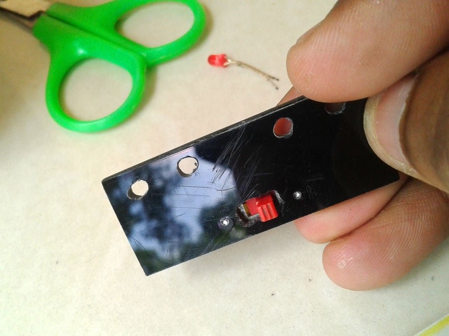
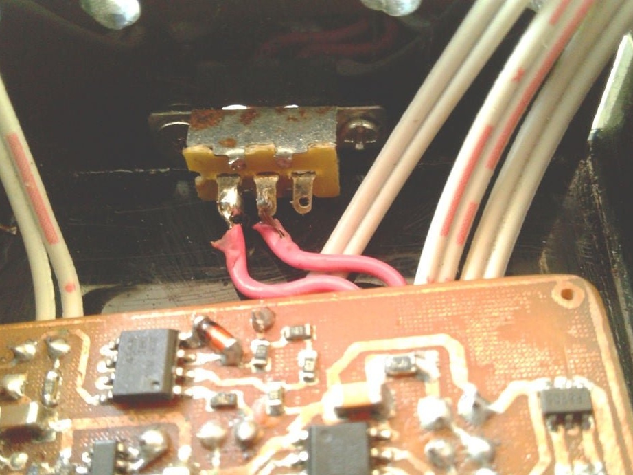
A slide switch secures the front panel.
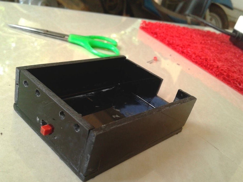
Glues the case.

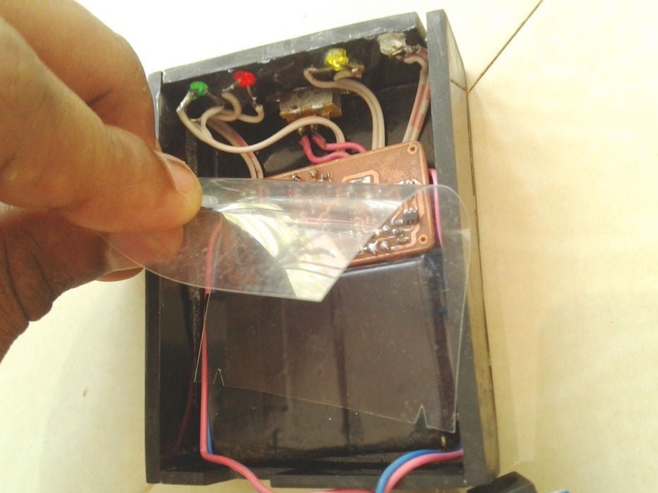
A double-sided tape secures the battery and board inside the case.
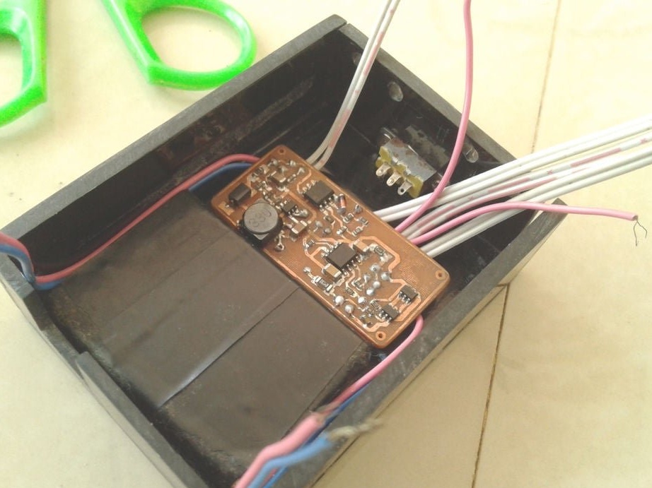

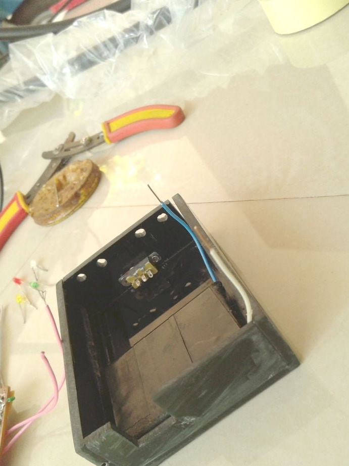


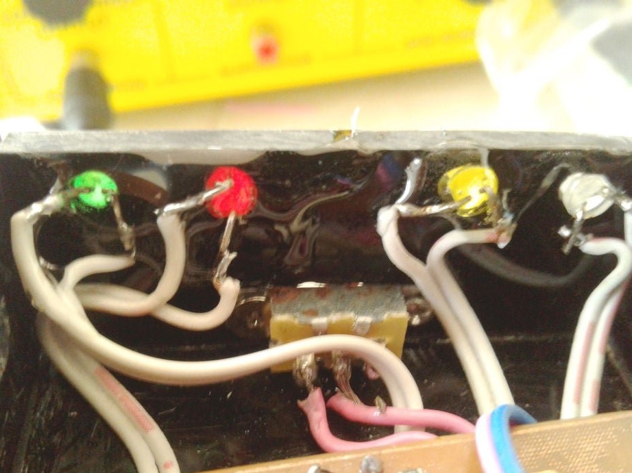
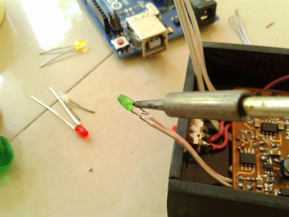
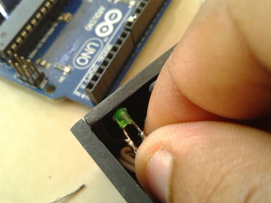
Make switch connections


and LEDs.


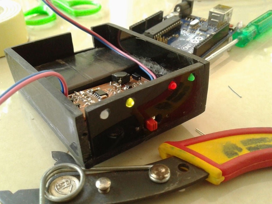
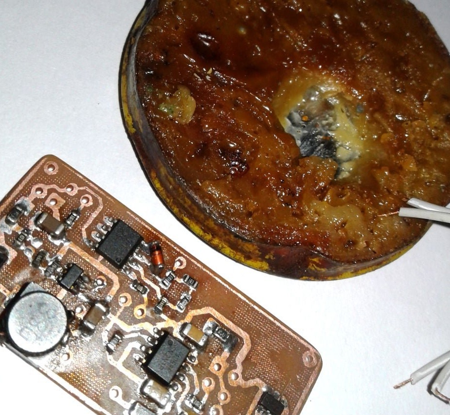
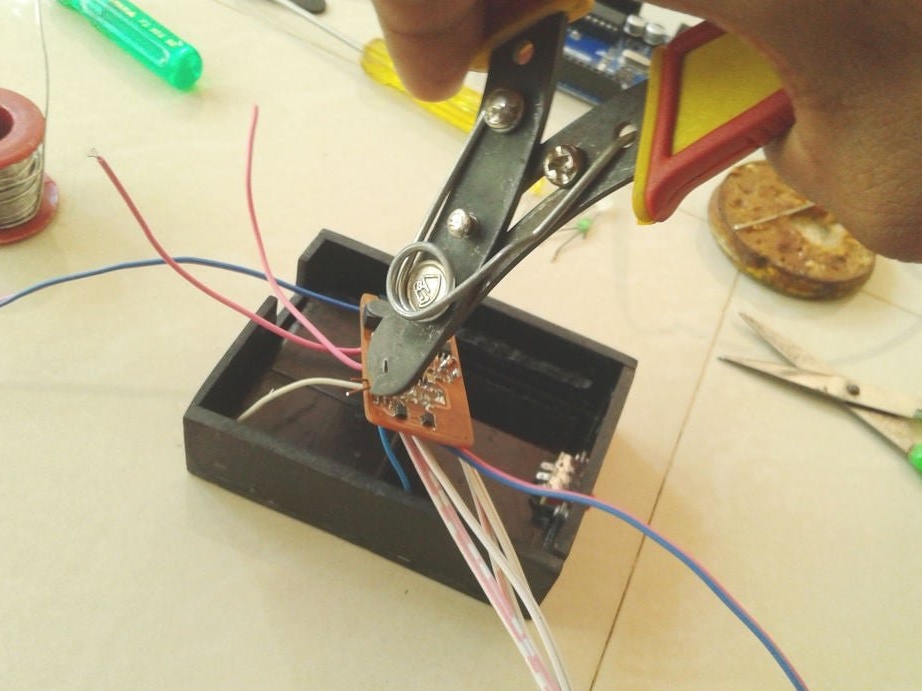
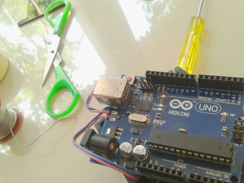
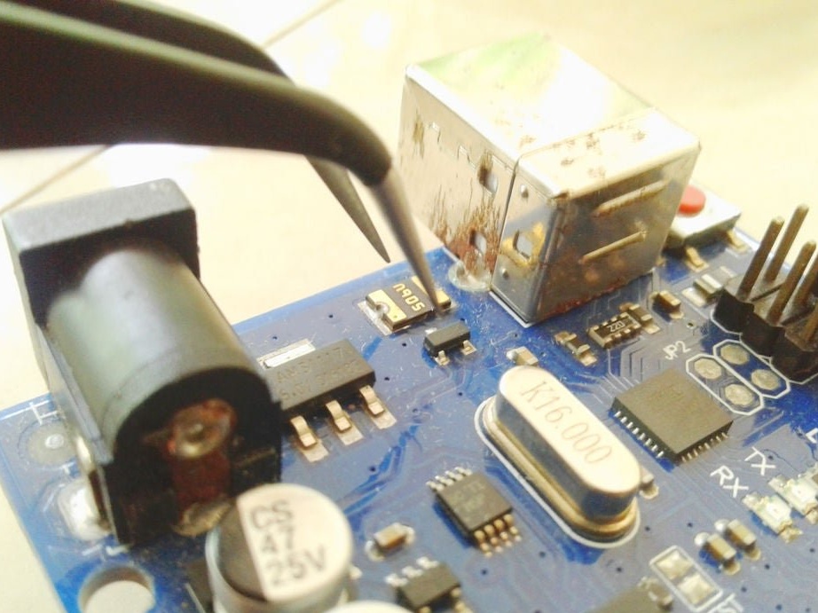
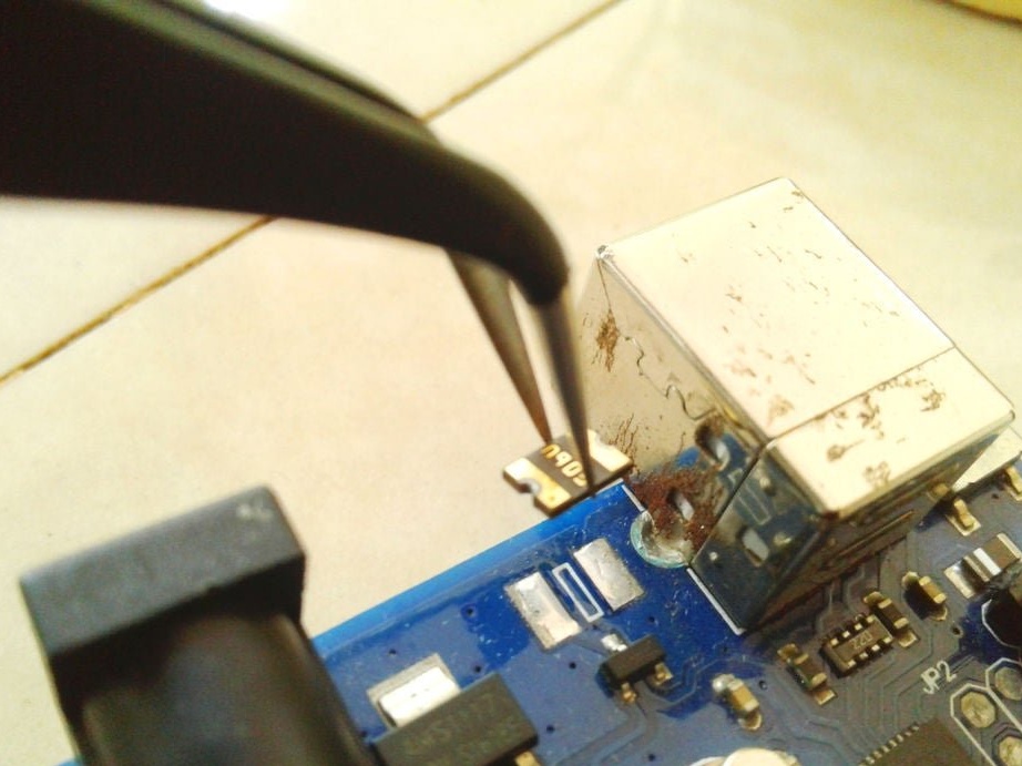
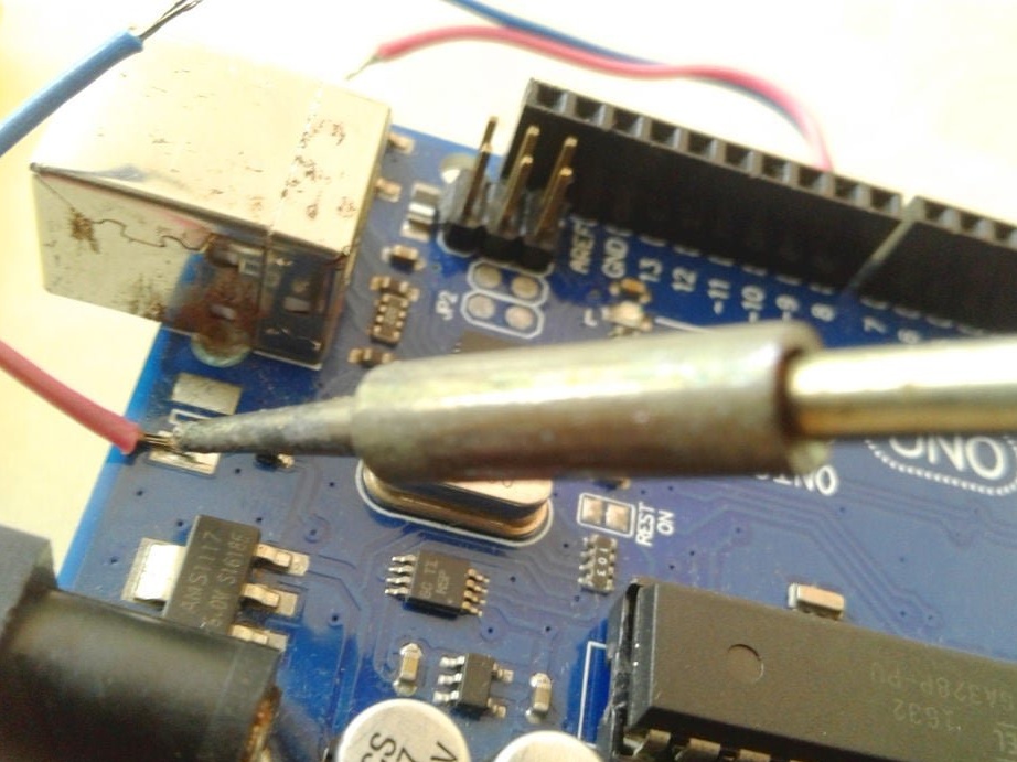
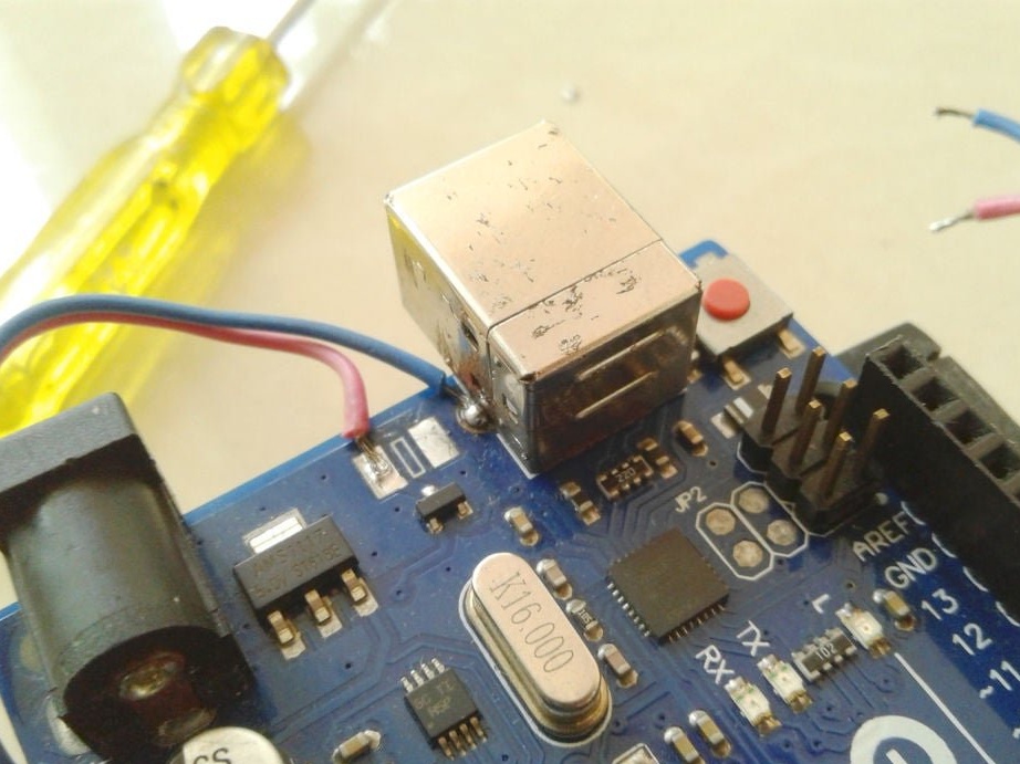
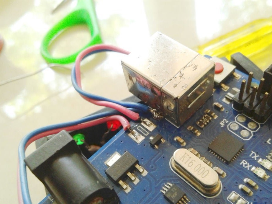
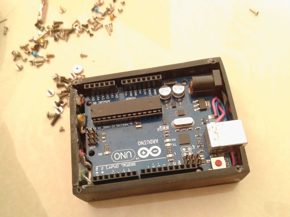
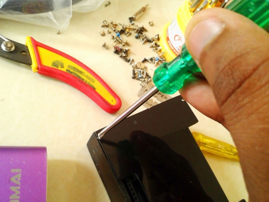
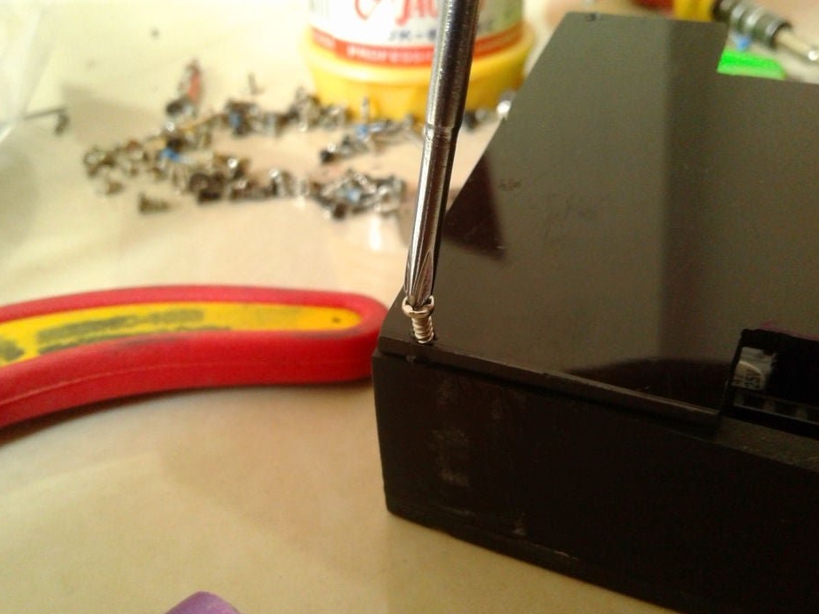
Now you need to connect Arduino. There is a fuse on the Arduino board. The master dismantles it and solders it to the pads of the wire and connects the printed circuit board.
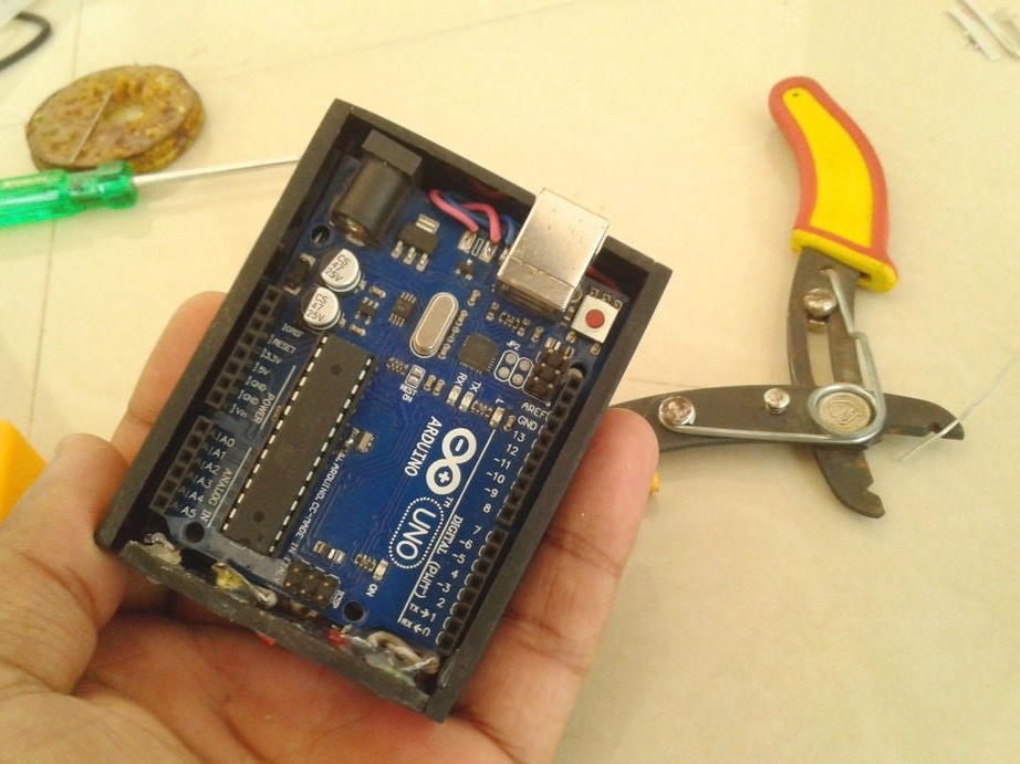
Installs in the Arduino case, placing a plastic insulator between it and the printed circuit board.
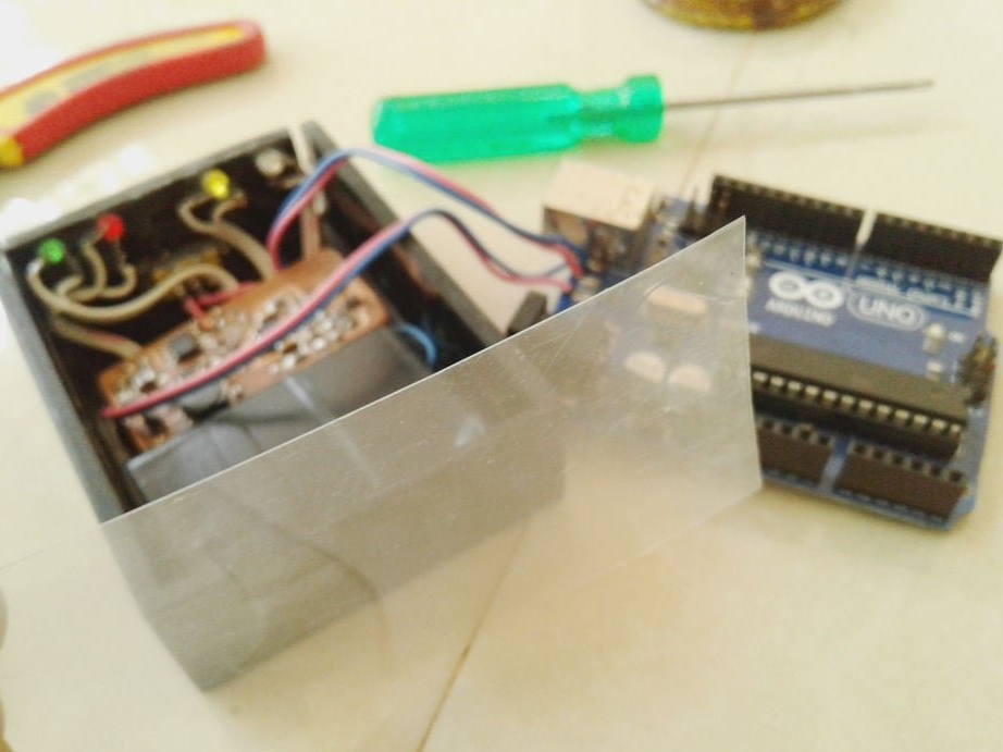
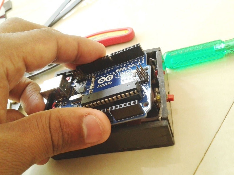
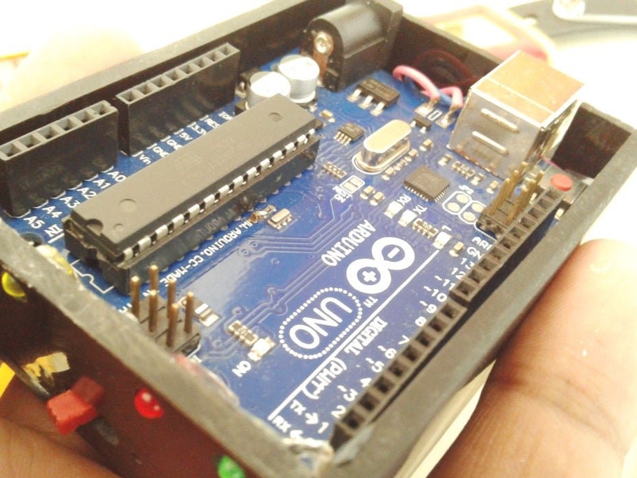
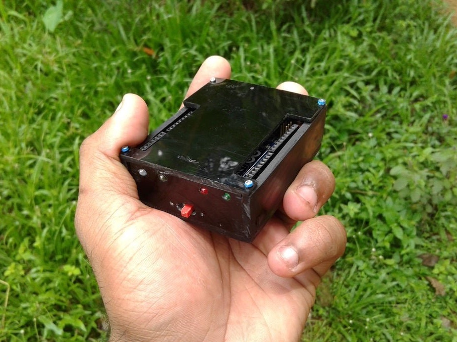
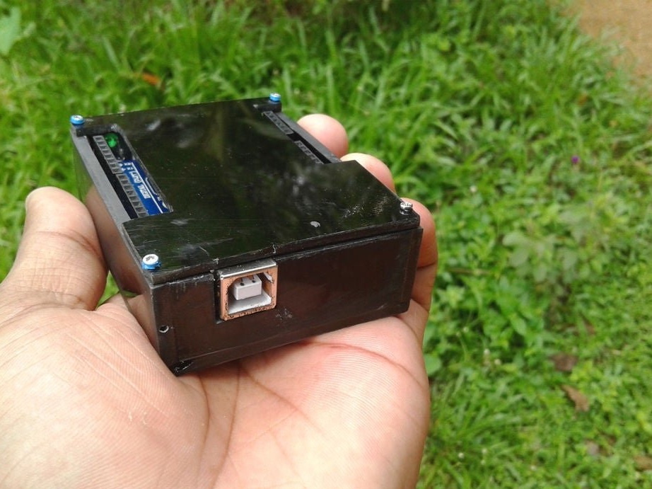
Installs the top cover. Fixes it to four screws.
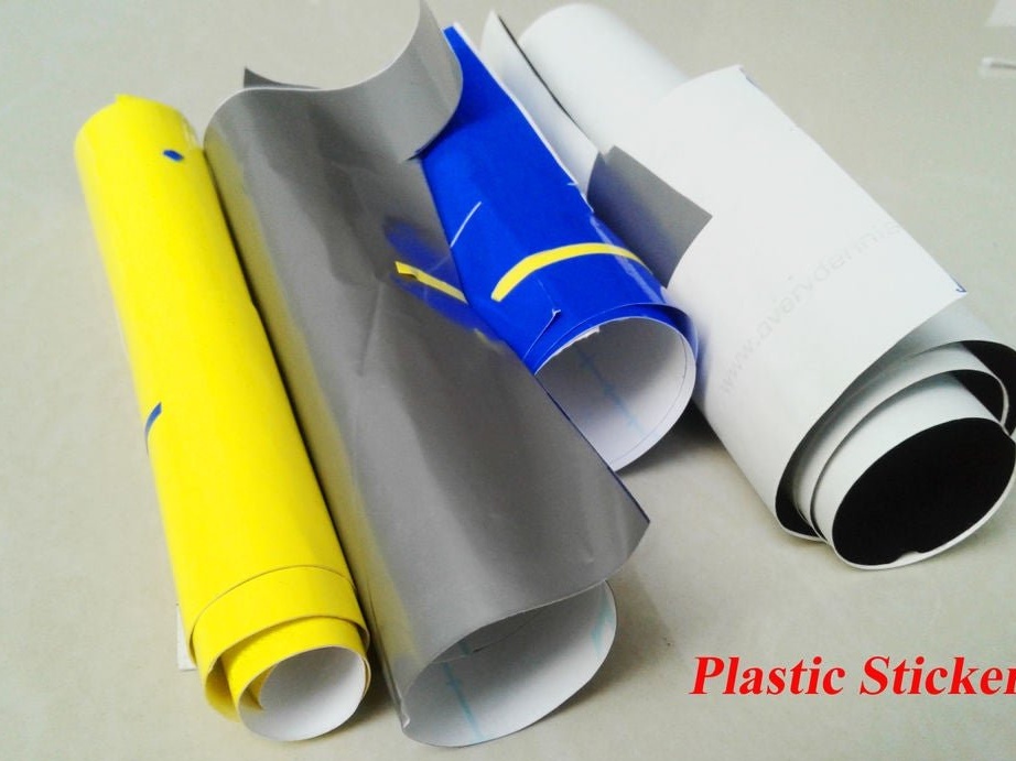
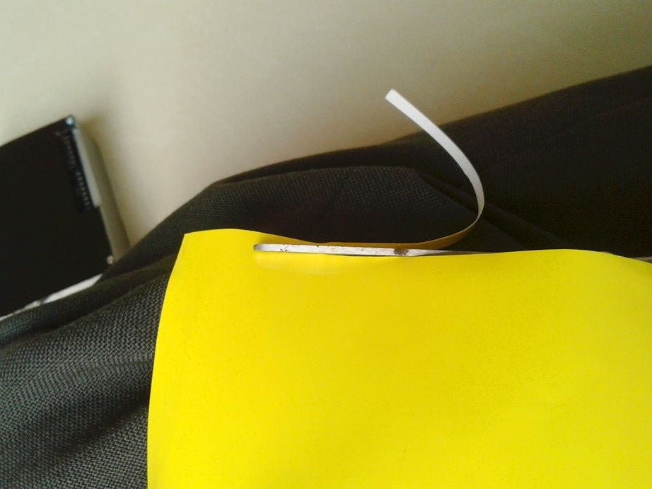
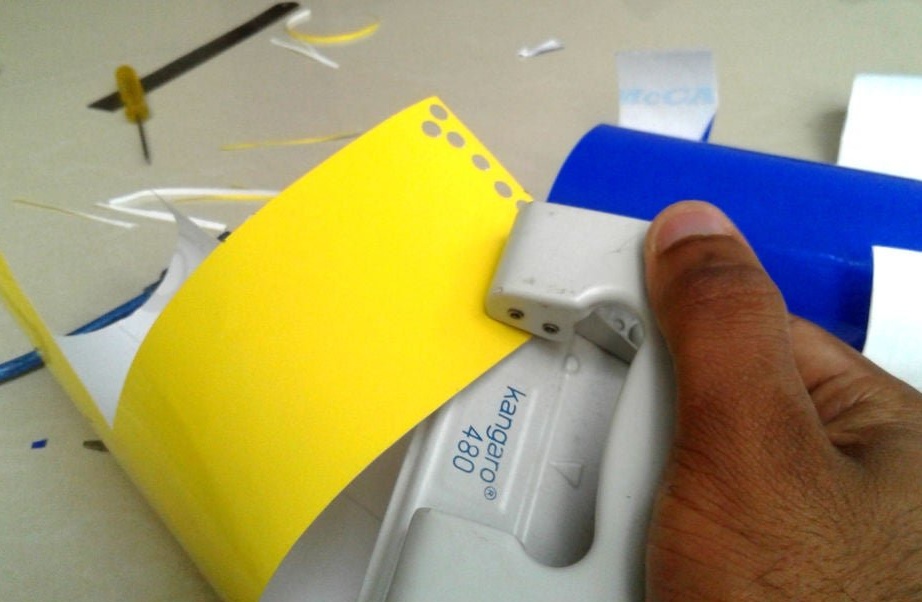
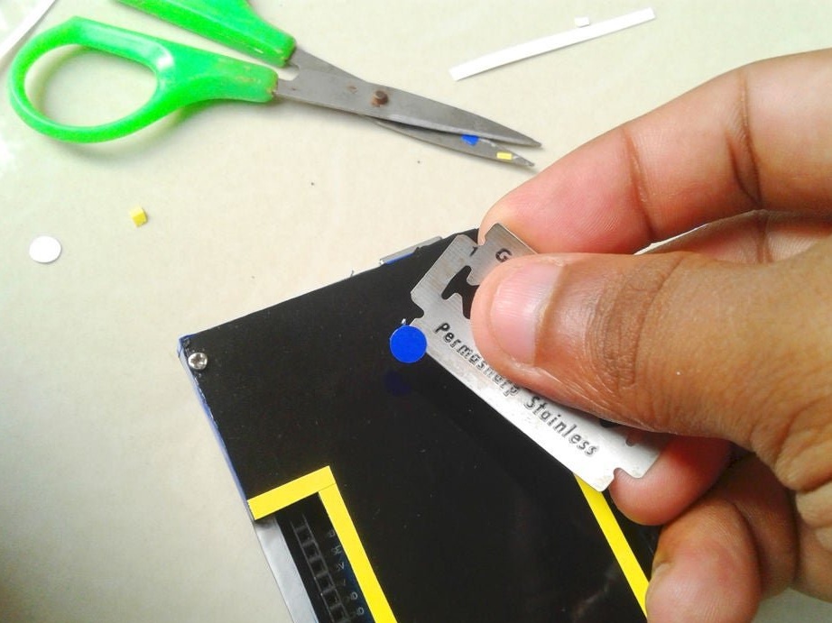
Seventh step: stickers
Cuts and glues stickers.
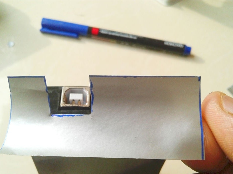
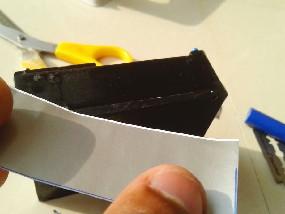
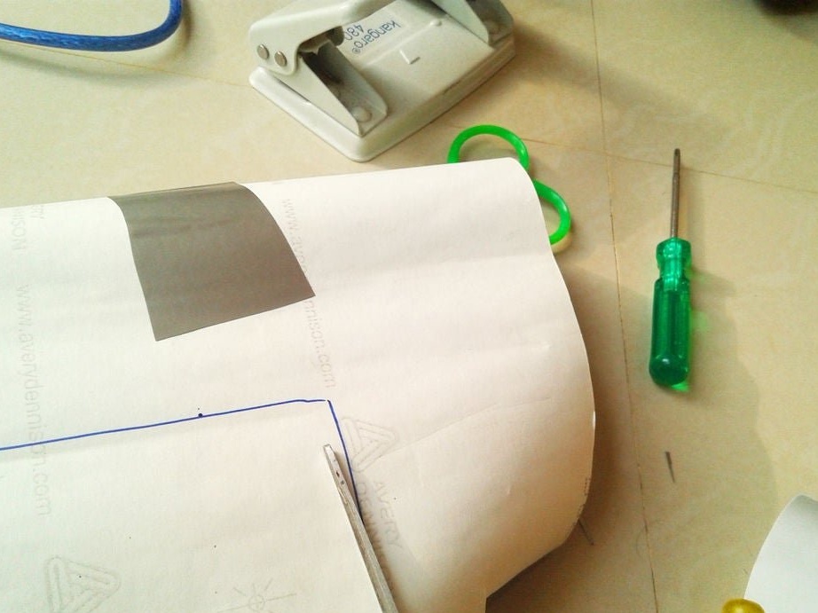

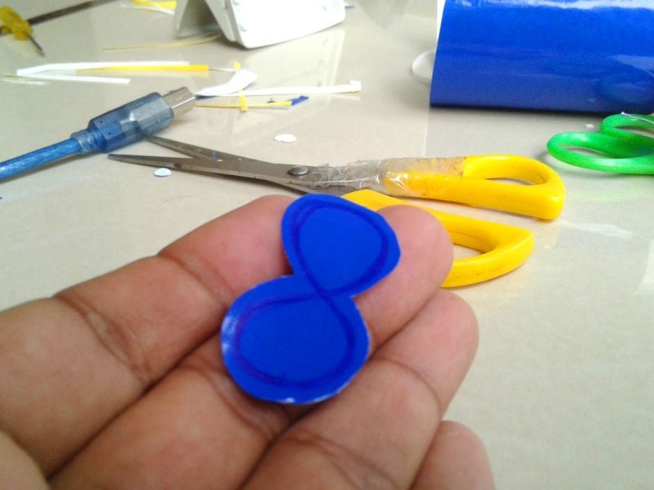
Adhes designer stickers.
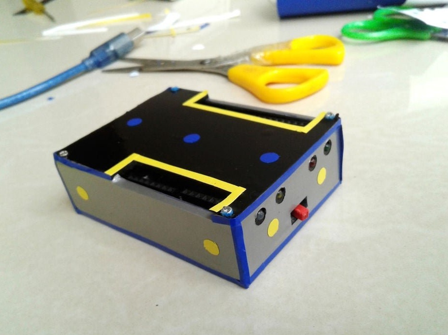
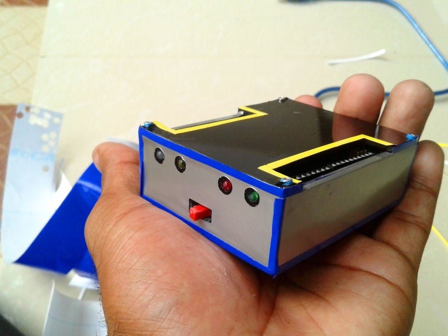
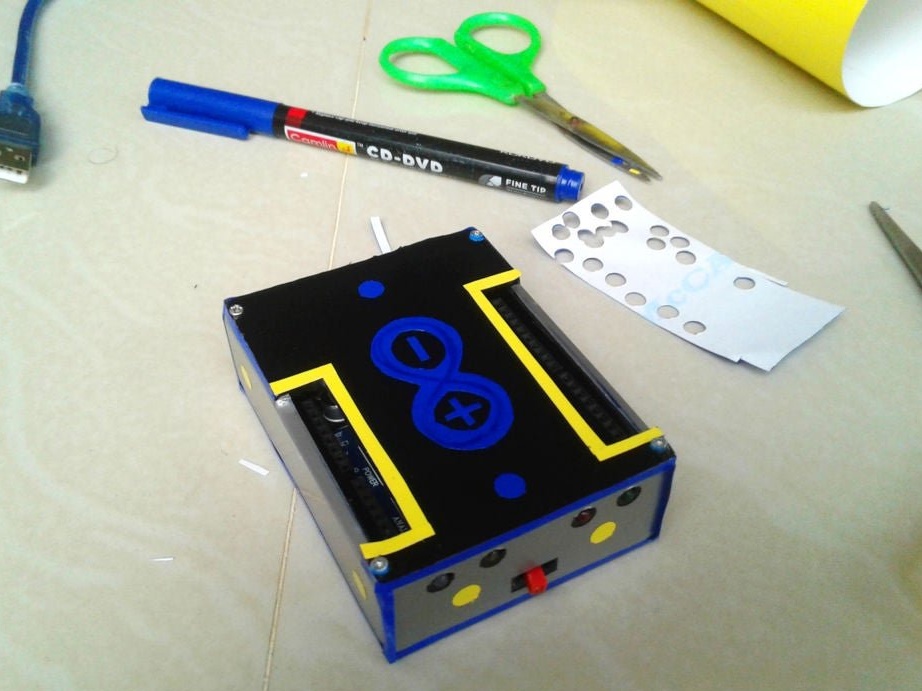
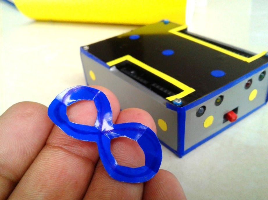
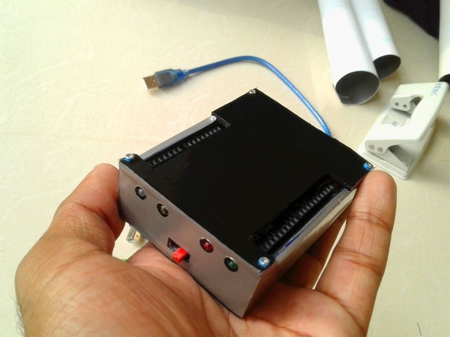
All is ready.