Video:
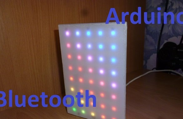
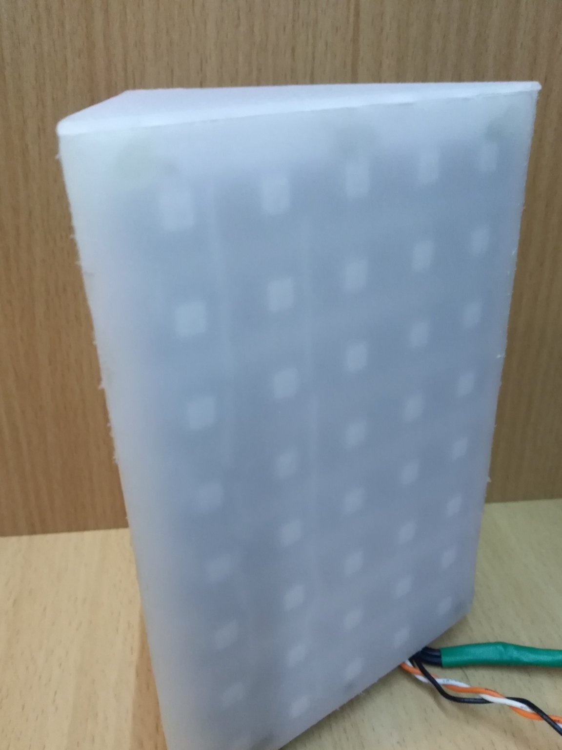
Greetings to all readers, authors and other visitors to the site "". Today I will share the instructions for making a table lamp in the form of a prism. The basis will be the WS2812 address LEDs. This is the second version of such a lamp. You will find instructions for making the first version here.
Unlike the first version, the controller in this lamp or night lamp will be Arduino. We also insert a Bluetooth module there for communication with the outside world. For management, we will use an application from the not-so-famous AlexGyver. Also, as in the first version of the lamp, take the WS2812 LED strip with a density of 60 diodes per meter. In total, 120 diodes, that is 2 meters, will be needed. In the instructions from the first version of this lamp, I missed a few important points, today I will correct this annoying misunderstanding.
Running shopping:
- Arduino Pro Mini 5V
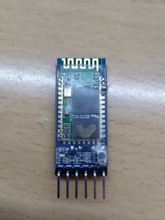
- Bluetooth module (HC-05 or HC-06)
- connecting wires
- A small piece of plastic tube with a diameter of 6 mm (suitable and thinner)
- Matte or "milk" plastic
- Corrugated cardboard
- USB-TTL
- USB connector
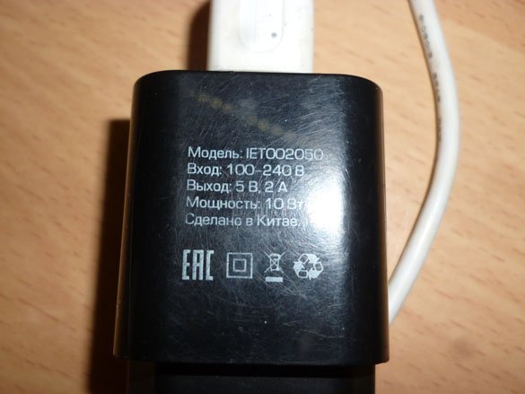
- Power supply 5 V, minimum 2 A
- Metal file
- Hot glue gun
- Soldering iron, rosin, solder, etc. etc.
Step 1 Assemble the lamp housing.
The case in the first version is the same in the second. Therefore, we go along the link
And we do everything from “Step 1 Preparing the base and LEDs.”.
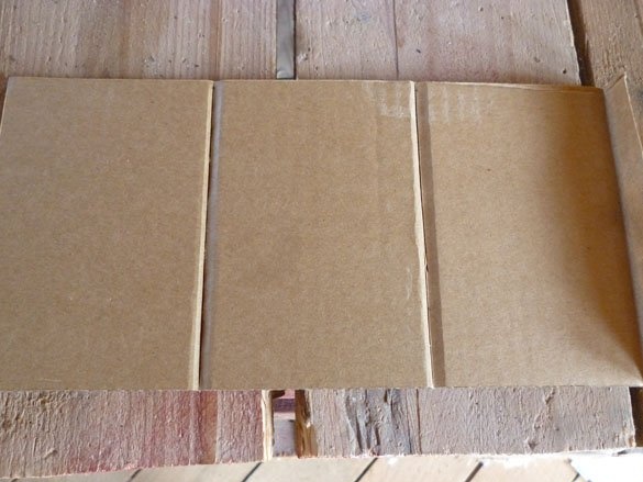
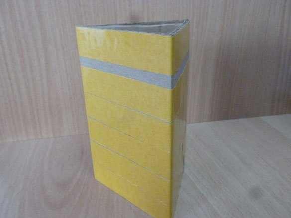
Cut the cardboard:
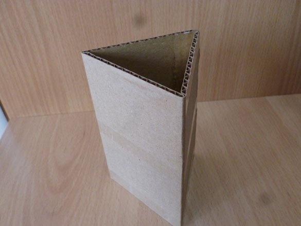
Add it in the form of a prism:
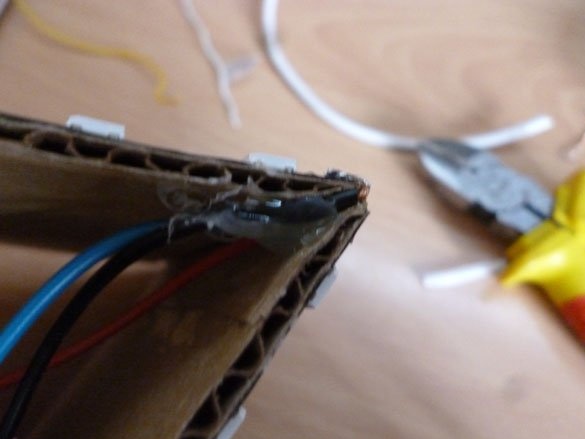
Adhesive tape of LED strip is not always enough, it is better to glue the cardboard base with double-sided tape:
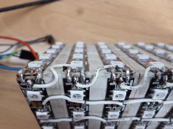
Now we can stick the LEDs, glue them in parallel lines, all in one direction:
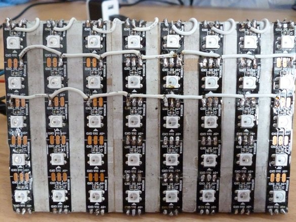
Do not forget to withdraw the wires from the first strip:
It was in this step that I forgot to write about the manufacture of a plastic topcoat. Corrected. We need plastic from 2 to 5 mm thick. The plastic should be matte or as it is also called "milk". It can be ordered in the online store or aliexpress. And you can do it like me. Take plastic from an unnecessary LCD monitor. Having disassembled the old LCD monitor or TV, we take out the matrix. Carefully disassemble the matrix itself, there should be several layers of light filters (films) and a matte scattering plastic. That's exactly what I made this lamp from. Having got such plastic, we cut out three rectangles from it.If you want the LEDs to be visible as dots, like my lamp, plastic must be glued close to the LEDs. In this case, the rectangles should be 137 x 95 mm. They look something like this:
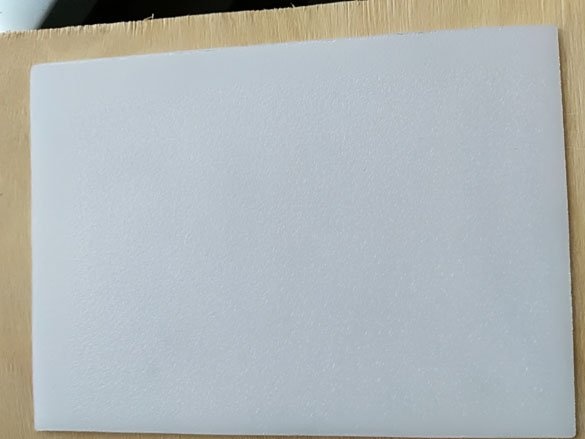
You can make the LEDs merge into one light source, then you need to fix the plastic at a distance of 10 - 20 mm from the LEDs. To do this, rectangles must be cut with a size of 137 x 110 mm. Plastic is best cut with a hand hacksaw. It turns out for a long time, but reliable. It is better not to use a jigsaw, because due to the fast movement of the file, the plastic will heat up, melt and stick to the file, thereby breaking the plastic and making the cut place not accurate.
The result should be like this:
Step 2 Electronic part.
As I said, the base will be the Arduino Pro Mini.
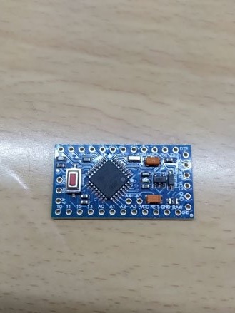
Take should be a version powered by 5 volts. To Arduino took less than a set, plugs should not be soldered. There are a lot of Bluetooth modules now, I think anyone will do. I will tune and write from HC-05.
Looking ahead, I’ll say there will be several versions of the sketch for Arduino. Depending on the sketch, there will be different options for connecting the Bluetooth module to the Arduino.
So, if you want Arduino to have both a computer and a Bluetooth module at the same time, choose sketches with a software communication port (SoftSeriel will be written in the names of the sketch). In these sketches, the Arduino computer is connected in the usual way (hardware TX RX), and connected to the Bluetooth module through the software implementation of the communication line. In such sketches, the connection is as follows:
Arduino Bluetooth
D7 (TX) - RX
D8 (RX) - TX
5V - VCC
GND –GND
In the names of sketches where it is impossible to simultaneously connect a computer and a Bluetooth module, BT will be written simply. To upload these sketches, USB-TTL is connected to the Arduino. And to work with the same contacts HC-05 is connected. That is, the connection is as follows:
Arduino Bluetooth
D1 (TX) - RX
D0 (RX) - TX
5V - VCC
GND –GND
In all sketches, the tape connects the same way. Do not forget that the tape needs food. And the tape, and Arduino, and HC-05 (HC-06) will be powered from one USB wire. You cannot connect this lamp to the USB port of a computer or laptop. The maximum allowable current on USB ports is 500 mA. This is not enough for normal lamp operation. You can connect to chargers with a USB port or power supplies with an output of 5 V and a minimum of 2 A.
The signal wire from the LED strip (Din) is connected to the D5 Arduino.
Step 3 Configure the Bluetooth module.
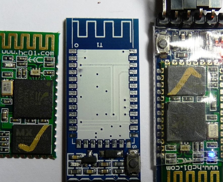
Now let's move on to setting up the Bluetooth module. Modules are very different:
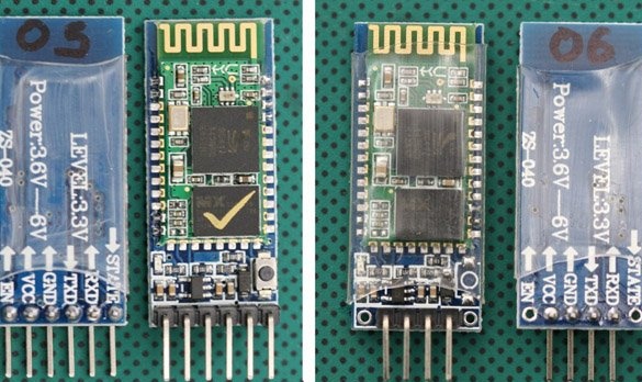
But they all connect the same way. And for starters, you need to connect to its USB-TTL as follows
USB-TTL - Bluetooth
TX - RX
RX - TX
5V - VCC
GND –GND
Open a terminal window or port monitor in the Arduino IDE. In the terminal settings, you need to set the speed to 38400, and set the sending of NL and CR. As for speed, I could be wrong, since different modules come with different default speeds. If the module does not receive and does not accept anything, look for the desired speed using the poke method. For HC-06, 9600, NL and CR are not needed. If you did everything correctly, try sending the command:
AT
The answer should be ok. If it came, then you can continue to configure the module. Change the name of the module to know what you are connecting to with the command:
AT + NAME
Now you need to set the speed of the Bluetooth communication channel. For the sketch “GyverMatrixOS” it is 9600. Enter the following command:
AT + UART = 9600.0.0
For all other sketches you need speed 57600. Install it with the command:
AT + UART = 57600.0.0
If you are confused about the settings, return them to the factory settings by entering the command:
AT + ORGL
I almost forgot! I recommend buying modules immediately soldered on a DIY board, for convenient connection to Arduino:
Step 4 Preparation of programs.
To edit and fill the sketch, we need the Arduino IDE. The latest version, which can always be downloaded from official site programs.
The following libraries must be added to it: Adafruit_NeoPixel, Adafruit_GFX_Library and SoftwareSerial. You can use the library manager, find the ones you need and install it. The manager is located in the Arduino IDE menu "Sketch" - "Connect the library." Or you can download them in the following archives:
adafruit_gfx_library.rar
adafruit_neopixel.rar
softwareserial.rar
If you want to use the “GyverMatrixOS” sketch, you need to go to the AlexGyver website on the project page and download the archive with the sketch and all the necessary libraries from there.
Step 5 Sketches.
As promised, I have a few sketches. The most simple. For you do not even need a Bluetooth module. Just fill it in Arduino, connect the tape without a Bluetooth module. And rejoice at the new night light, which will change in a circle a large number of different effects:
ard_prizma.rar
Brightness can only be changed in a sketch in stock:
strip.setBrightness (10);
Simple, reliable. Plug in and everything is ready.
The next sketch works on a hardware serial port, commands can be sent from a computer through the terminal. Or by connecting the Bluetooth module through the application:
ard_prizma_bt.rar
A sketch working on a software serial port, you can connect HC-05 (HC-06) and a computer at the same time.
ard_prizma_bt_softserial.rar
For lovers of a large number of effects and great functionality (including a couple of games, etc.), I advise you to use the sketch "GyverMatrixOS"Downloaded from the project site.
Settings for our prism for the sketch "GyverMatrixOS":
USE_BUTTONS 0 // use physical control buttons (0 no, 1 yes)
BUTT_UP 3 // up button
BUTT_DOWN 5 // button down
BUTT_LEFT 2 // button to the left
BUTT_RIGHT 4 // button right
LED_PIN 5 // ribbon pin
BRIGHTNESS 10 // standard maximum brightness (0-255)
WIDTH 15 // matrix width
HEIGHT 8 // matrix height
MATRIX_TYPE 1 // matrix type: 0 - zigzag, 1 - sequential
CONNECTION_ANGLE 3 // connection angle: 0 - lower left, 1 - upper left, 2 - upper right, 3 - lower right
STRIP_DIRECTION 2 // tape direction from the corner: 0 - right, 1 - up, 2 - left, 3 - down
SCORE_SIZE 0 // the size of the letters of the account in the game. 0 - small (for 8x8), 1 - large
FONT_TYPE 1 // (0/1) two kinds of small print
GLOBAL_COLOR_1 CRGB :: Green // The main color No. 1 for games
GLOBAL_COLOR_2 CRGB :: Orange // main color No. 2 for games
Step 6 Configure the phone to control.
We will use a telephone to control the lamp. Any program for working with Bluetooth, for example, “Arduino Bluetooth Control,” is suitable for my sketch. It can be downloaded from "Google play»
For a sketch from AlexGyver you need his own program, it can also be downloaded to your phone or tablet with “Google play»