» Electronics » Metal detectors »Scheme of a more advanced detector" Kid FM2 "with metal selectivity

The scheme of a more advanced detector "Kid FM2" with metal selectivity


The Kid FM2 circuit is a bit complicated compared to the simpler "Kid FM”, Added new parts, added light indication of metals, the sound in the speaker is amplified (headphones are not needed), and the device itself has become more stable in operation. But all these improvements will not hinder to assemble it to people far from electronics.

The device is powered by a simple crown 9c, the detection depth is basically no more than the diameter of the search coil. Perfect homemade metal detector for the beach or to the lookout.

For assembly we need:
1) Textolite
2) Drill
3) Varnished copper wire 0.3mm
4) Soldering iron

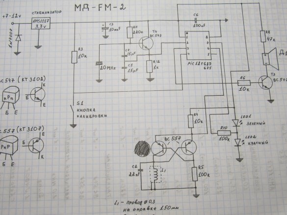
Here is a diagram of the improved Kid FM2

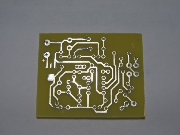
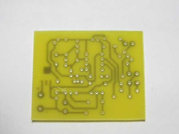
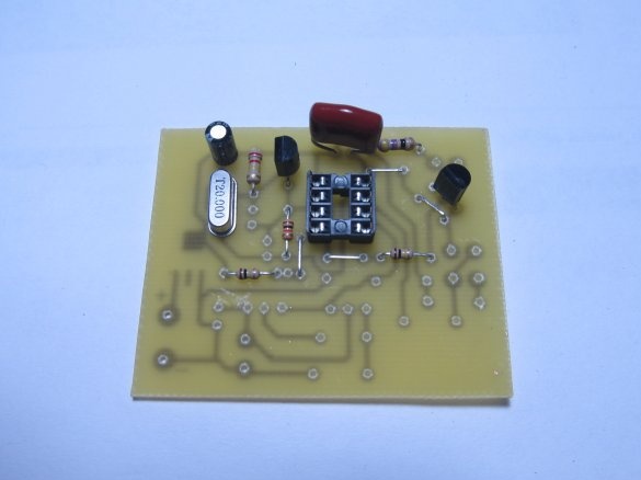
I specifically made the board for DIP components, it’s easier to mount


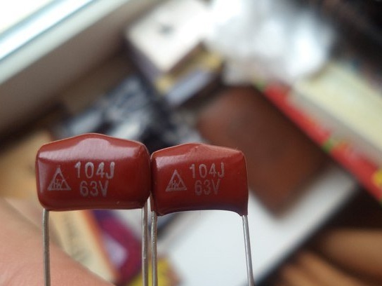
I must say right away that the capacitors C2-22nF and C6-100nF should be film
The scheme of a more advanced detector

We place all the details on our board according to the scheme

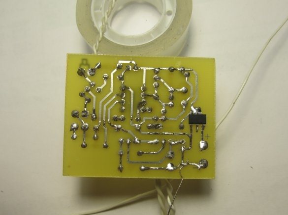
There are circuit boards on the Internet. But they are all in SMD, I did not find in DIP, so I did mine. I’ll post the file with the board below, but the details and jumpers are not signed on it, so it will take you to collect from the photo or make your own board or SMD.

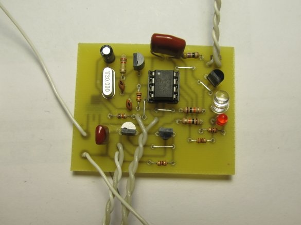
Well, everything is soldered into place


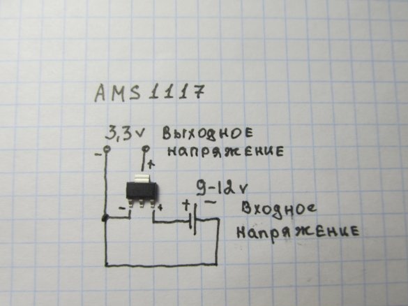
Voltage stabilizer AMS1117 -3.3v.

I advise you to take the LEDs in different colors, I took red for ferrous metal and blue for non-ferrous.

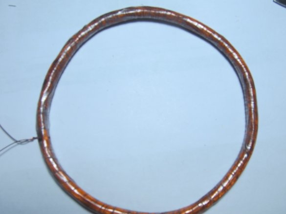
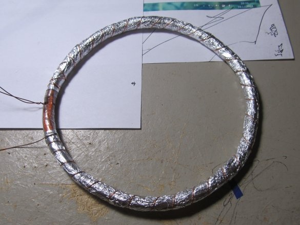
Proceed to winding the coil. The diagram says about a coil with a diameter of 15cm. But I decided to do less, because the smaller the coil, the finer the find she sees, if the coil is large, then the detection depth is a little more. But she sees little goals. Since the depth of detection in this metal detector is not very large, I decided to make a 10-11 cm coil for myself. To do this, you need to wind a wire on a 10 cm mandrel (I do not have 0.3, I wound 0.4) 130 turns.

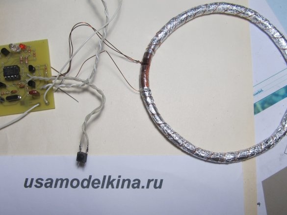
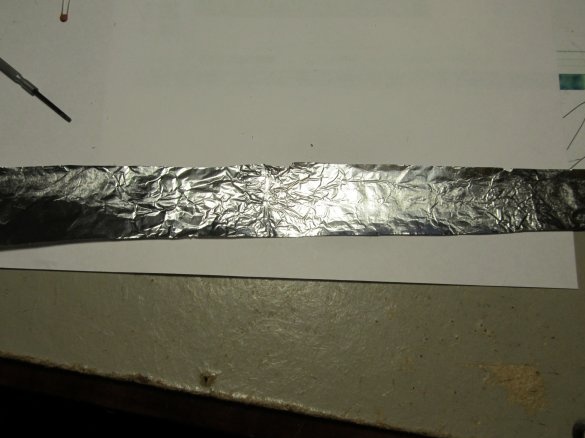
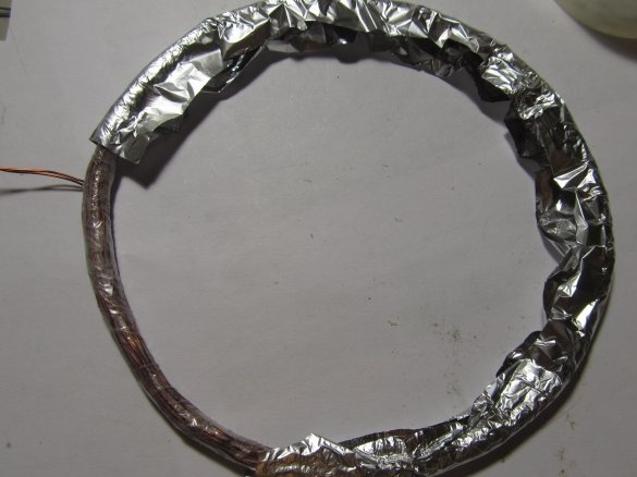
Coil as in first baby wrap with tape and screen.


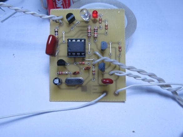
Here is a photo of the entire device assembly

Next, you need to flash the microcontroller and you're done.

When you turn on the device should make a sound (peak-fute), if the Fute is, then the device turned on and started working.If at all, I didn’t pick it, then the error in the board or not working quartz.

If you pick it up, but there is no treasured Fute, then either the coil is not wound correctly or the wrong capacitor C2 is 22nF. It didn’t start for me for a very long time, everything was picking and picking, but there was no treasured Fute. It turned out that instead of a 22nF film capacitor, I put a simple ceramic one and did not tighten the coil tightly and did not shield it.

Basically, the device is not very difficult to assemble, the main thing is to flash the microcontroller, who does not have a programmer, please contact, I will help with the firmware or in comments.

Below I posted a video of the metal detector, as well as firmware and board files in DIP.

VIDEO WORKS


FIRMWARE MetFM2_675.rar [1.99 Kb] (downloads: 7940)

PAY Plata-DIP.rar [7.13 Kb] (downloads: 7985)
9.7
10
8.3

Add a comment

    • smilesmilesxaxaokdontknowyahoonea
      bossscratchfoolyesyes-yesaggressivesecret
      sorrydancedance2dance3pardonhelpdrinks
      stopfriendsgoodgoodgoodwhistleswoontongue
      smokeclappingcraydeclarederisivedon-t_mentiondownload
      heatirefullaugh1mdameetingmoskingnegative
      not_ipopcornpunishreadscarescaressearch
      tauntthank_youthisto_clueumnikacuteagree
      badbeeeblack_eyeblum3blushboastboredom
      censoredpleasantrysecret2threatenvictoryyusun_bespectacled
      shokrespektlolprevedwelcomekrutoyya_za
      ya_dobryihelperne_huliganne_othodifludbanclose
155 comments
The Yuri guest controller 675 (in ex. 629) has an ADC on the ports. Therefore, several other programs ... you are not registered here, so the file can not ... You can see.-Download from My disk
Guest Yuri
I took this scheme as a basis. The controller really acquired 12F629, and the photo on the board 12F675. The firmware file is also called in the MetFM2-675 archive, but it is possible to flash 12F629 in microbrn, and the hex file for 12F675. And why the fifth leg of the microcontroller is not involved. Do I need to purchase a 675 chip now? In general, there are no signs of work !! How to choose the correct hex file? I collected radio components for a year, I just can’t solder smd components, I was looking for just such a circuit. With controllers why such a spread 12F629 / 675 ??? Help me please!
I don’t know about quartz, and the piezo emitter worked quietly, stuck a speaker of 8 ohms, it works fine.
Welcome all! Please tell me if instead of 20 to 16.9 quartz is replaced, dr is not easy, then how it will work or not. And what to put the piezo-emitter or speaker on the sound, and even when flashing the peak lost the constant (
Thanks to the author, everything works.
Good day to all! My question is: can I put two search coils on the metal detector Kid FM-2 at once, one small diameter and the other large?
Download the signet to Yandex, Google or a mail disk and leave a link to the file.
Quote: DasAlex
Hi, people here drew in detail the baby's board on dip components, to the author of the ATP for the idea. Here is the board itself, just look there, I inserted the 4007 diode correctly?

In short, some kind of nonsense. I can’t add a Lay signage to anyone who needs to write a skin or if I’m not doing it right, correct me
Hi, people here drew in detail the baby's board on dip components, to the author of the ATP for the idea. Here is the board itself, just look there, I inserted the 4007 diode correctly?
We can flash PIC12F675 -I / P
Hello. Can you help with a stitched microcontroller?
There is also "Send a message" ... on the Pronin button (PM)
And E-mail is
And how to contact you to discuss the details?
We have a PIC flasher and you can flash it ...
And the debugged shawl on the PIC12F675 with a small coil. It was supposed for a manual MD-pointer
Does anyone have a PIC firmware? Can someone flash mikruhu or provide a ready-made fee for denyuzhku?
For a long time I’ve been looking for glands with a homemade device with discrimination, I developed a circuit with me looking for my friend with an imported metal detector which is much worse in sensitivity and often incorrectly determines non-ferrous or ferrous metal, for example, very often it determines how small a toy costs 25,000 rubles and my homemade product is better in terms of detection range and even very small objects it clearly defines a lot of interesting finds of a brooch with stones, scales, a saber, the truth on it killed a lot of time for restoration and why shouldn't a person take the device and don’t try if you assembled this downtime, and over time it will also collect more complicated ones.
Quartz. If you ask such questions, then it’s too early for you to try to reproduce this unit.
Hello in the picture (20MHz) what is this?
What depth of detection for example 2 ruble coins made a pirate experimentally with a search coil reached 33 cm.
Quote: To Delusam
If you really want to understand this craft,

then check your country's laws governing these actions. Sure! Otherwise, you run the risk of running into big trouble.
scratch
I read this topic and I think that most fans of this topic think, here they’ll "clog" the appliance and "trample" to look for treasures. Not so much there is a desire to make a device, how to run faster to look for a "treasure". I don’t even want to do it, they ask some to send ready-made ones ?!
I’ll disappoint you, it’s not so simple. Making a more or less good device is not easy. All that is written about these homemade products is a little better than the detector receiver (if in comparison). The characteristics of the device given here are very, very approximate. In fact, they will really disappoint you.
If you really want to comprehend this craft, buy used even the most primitive and it will be better. Try to understand the essence of working with the device, it is not as simple as it seems. Perhaps now to rent.
Here is one of the characters in the movie "Trembita", S. Kramorov.

also was a fan of looking for pieces of iron.
I advise you to think over everything before you start doing this.
yes An amateur seeker with experience. There is even a mine detector, like Kramorov’s.
Most likely at 20cm in the middle of the coil there will be a sensitivity failure. And there will be no 20cm. This is not an impulse. For 20cm we have Clone PI-W (pulse).
Kid-2 I think to give for 1600 rubles.
and if the coil is 20 cm, it will take 20 cm?))

How much are you selling?
I have assembled on a PIC12F675. What coil do you need?
I wound ~ 5.5 cm
It was supposed to be in the pinpointer case.
I can sell
Good time of day. Maybe someone will sell the finished MD FM-2 v2
For some reason, Lay gives me the error "ist keine Sprint-Layout Datei" opens other files from the computer.
Hello, I ask you to discard the full name of the parts for the scheme "Kid FM2"
Is there a difference for resistors 0.125 W or 0.25 W set?
Maybe someone will come in handy. Everything seems to be right.
Hello.
I am interested in one question. There was one comment and you did not respond to it.
I quote;
"with resistor R8, power supply + 7-12 volts according to the scheme, you have 3.3 volts.
No problem?"

I found 2 circuits, the original one like that of the author - R8 is powered by + 7-9v
And as you have - R8 is powered by + 3.3V

Maybe there were problems because of this.
Where did you get your circuit?
I collected it, it worked 1 time after the correct collection, the author you didn’t write much here about the controller firmware, about what parameters for this device to set after choosing the firmware, I collected from the beginning it just picks up and everything, and the squeaks are not the same as on the video, I thought the reel is not so 10 times rewound in every way. So I will say this, the coil is of little importance in this device, correctly set the parameters in the ICprog program, the oscillator and checkboxes must be set correctly differently or it will not work at all or it will not work correctly. As soon as I picked up the parameter using the scientific poke method, everything turned on from 1 time and it worked. The coil turned out to be nothing to do with. In general, I’ll say this about shielding: reel and check without a screen, the only thing is that put the coil away from metals from metals 30cm + - I experimentally wound a second coil of 83 turns of 0.4 wire according to a 20cm diameter program, turned on to check without a screen everything worked fine, I need a screen so that outside the coil does not react to metal, but only inside it ...
Hooray, it worked!
Thank you for contributing all possible answers to my questions.
It didn’t work right away, I bought stabilizers in the store (slipped some crap), ordered from China, soldered - and voila, it all worked right away)
Author
Sent by mail
Author
Shot on slippers, coil not connected

Heh, how can I upload a photo?

Come on via email or email? So as not to disturb everyone here.
Author
Well, come on a photo of the board from all sides, maybe there is a jamb?
So when inserting a stone into the board and applying power, there is no reaction - neither light nor sound ...
Author
Zeros are fine, just the code is protected. If it shows zeros. and there is a constant below, then everything is fine.
After programming, I counted the stone - in response, only zeros in the code and a constant below. I tried to reflash a couple of times - the result is the same. What is the reason?

So I suppose there should be a code that we drive there, and not zeros?
Clear. So uh, I erased. It is necessary to calibrate.
Author
when you turn on the programmer and insert the microcontroller, press the read MK button, the programmer reads the PIC, since there is no program in it, all the cells will be FFF FFF FFF, and at the very bottom in the lower right corner there will be 4 digits (34FF, 3434,) or something like that, this is a constant. These four digits must be remembered and after loading the program into MK, manually these four digits must be entered back where they were.
If the PICkit programmer, then it automatically rewrites the constant itself
sort of like that
Hey. Can you hear more about the constant? I assembled the device, the programmer, but I just can’t flash the microns. With ABP, it’s much easier .... I use the 629th, after the firmware it gives an error code.
Author
shurik_8888,
it can be restored, google look, I saw somewhere.
If flashing with the PIC KIT programmer, it remembers the constant itself and then writes it during firmware. All other programmers do not do this (you have to write a constant on a piece of paper, and insert it after firmware)

But if more than 6 volts were applied to the microcontroller, consider that you buried it (((
found my first jamb (
Is the controller lost if you missed the item with a constant during firmware?
Author
Power from 9 volts.
Common problems:
1-Wrong reel
2-Error when PIC firmware (forget about the constant is 4 digits below in the window where the program code shows)
3-Errors on the board
Author
Power from 9 volts.
Common problems:
1-Wrong reel
2-Error when PIC firmware (forget about the constant is 4 digits below in the window where the program code shows)
3-Errors on the board
Basking - I understood why, fed 12 volts. Now I’ve taken the crown, but it’s shrunken. (In what range do I feed the baby? If the LEDs by ratings are unknown to me and set the power supply with a margin, will they only dim more brightly? What are the most common mistakes? Checked - everything is without snot and in accordance with the ratings Can there be problems with firmware, or with PIC?
Author
then the stabilizer is not connected correctly

firmware can be any of the three

We advise you to read:

Hand it for the smartphone ...