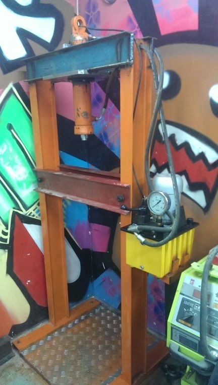
The scope of hydraulic presses is quite wide: they can be used in car repair shops for pressing in, pressing out bearings, gears, shafts, etc. They are also used for stamping metal parts, pressing wooden shavings, plastic, rubber. Ready-made machines cost from 100 thousand rubles. In this article, the author describes a fairly budgetary, and at the same time high-quality design of a hydraulic press that can give a maximum force of 35 tons per 50 square centimeters.
Creating a machine will require access to the following equipment:
- Lathe;
- Drilling machine;
- Welding machine.
Tools such as a grinder and a drill will also be required.
The materials needed to create will be listed in the article itself.
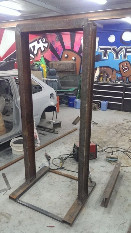
In the process of creating the machine frame, it is important to pay great attention to its strength, since it will be subjected to tremendous mechanical stress. The metal thickness here should be sufficient to withstand the forces exerted by the hydraulic cylinder and not bend. The author of the article used 14 T-beam as the basis. A “P” shaped bed is boiled out of it, at the bottom of thinner channels and corners a base is made on which it will stand.
Approximately in the middle, a working platform of two thick channels is welded:
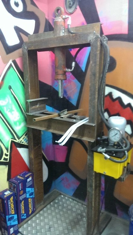
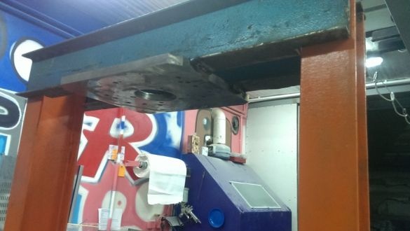
Initially, the author used another fastening of the hydraulic cylinder, but it vomited from the bed, so it was decided to dismantle and make a new one. If earlier the cylinder was simply welded to the beam, now it was decided to plant it through the flange on a 20 mm plate. The plate itself will be located on two T-beams.
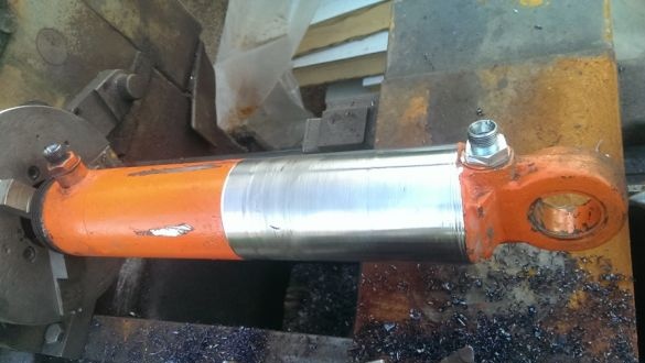
In order to place the cylinder in the flange, the cylinder is machined on a lathe.
Here is the output:
The flange is made of a car hub, machined on the same machine:
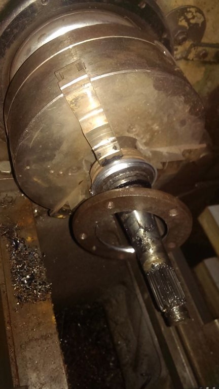
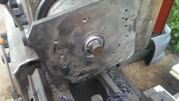
Then a metal plate 20 mm thick was used. In order to make a hole in it for a cylinder, it needs to be somehow fixed into the machine.To do this, a round boss is welded to the center of the plate. For her plate is mounted in the machine.
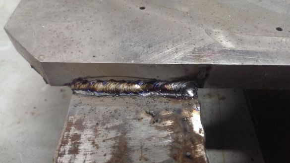
Next are welding work. The plate is welded to the beams:
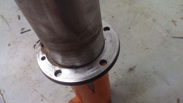
The flange is put on the cylinder, and scalded in a circle:
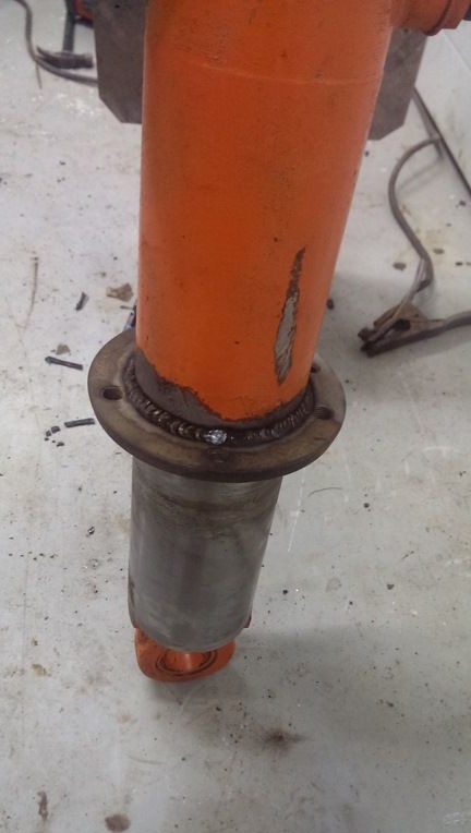
In order for the cylinder to sit evenly, the adjacent surface of the flange is machined on a lathe:
A plate with beams welded to it is installed in its place and welded:
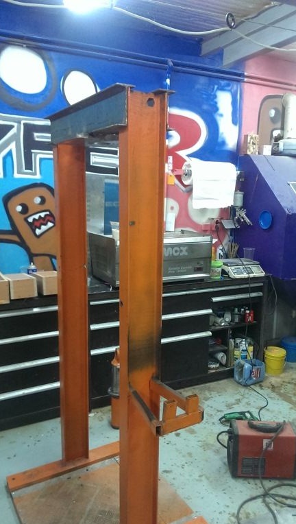
Then, holes are drilled through the hub counter holes in the plate, through which the fixing bolts will pass.
In order for the cylinder to be attached not only at one point, another flange is machined, put on the top of the cylinder and welded to the beams.
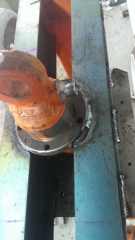
T-beams in the upper part are welded together and the structure is ready. Next, an oil station is installed, supply hoses and the machine is ready.


