
This article will talk about how do it yourself You can make such an interesting device as Levitron. In fact, a levitron is a spinning top or other object that soars in space due to the action of a magnetic field. Levitrons are diverse. The classic model uses a system of permanent magnets and a spinning top. It hovers over the magnets during rotation due to the formation of a magnetic cushion underneath.
The author decided to improve the system a bit by building a levitron based on Arduino using electromagnets. Using these methods, the top does not have to rotate to soar in the air.
Such a device can be used for various other homemade. For example, it can be an excellent bearing, since there are practically no friction forces in it. Also, on such a homemade product, you can conduct various experiments, well, or play friends.
Materials and tools for manufacturing:
- microcontroller Arduino UNO;
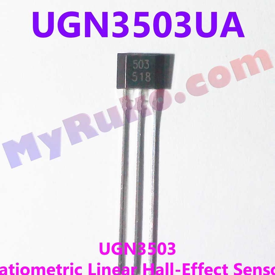
- linear Hall sensor (model UGN3503UA);
- old transformers (for winding coils);
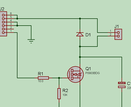
- field effect transistor, resistors, capacitors and other elements (ratings and brands are shown on the diagram);
- wires;
- soldering iron with solder;
- 12V power supply;
- cork;
- a small neodymium magnet;
- hot glue;
- The basis for winding coils and materials for creating a homemade body.
The manufacturing process of levitron:
Step one. Make a coil
The coil will be an electromagnet, it will create a magnetic field that will attract the top. As a top there will be a cork on which a neodymium magnet is attached. Instead of cork, you can use other materials, but not too heavy.
As for the number of turns in the coil, here the author did not mention such a figure, the coil was going to the eye. As a result, its resistance was about 12 ohms, height 10 mm, diameter 30 mm, and the thickness of the wire used should be 0.3 mm. There is no core in the coil, if you need to make a heavier top, then the coil can be equipped with a core.
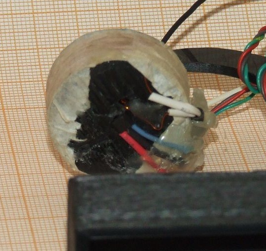
Step Two The role of the Hall Sensor
In order for the top to soar in the air, rather than sticking tightly to the solenoid, the system needs a sensor that can measure the distance to the top. As such an element, a Hall sensor is used. This sensor is capable of detecting the magnetic field not only of a permanent magnet, but can also determine the distance to any metal objects, since such sensors themselves create an electric magnetic field.
Thanks to this sensor, the top always keeps at the right distance from the solenoid.
When the top begins to move away from the coil, the system raises the voltage. Conversely, when the top approaches a solenoid, the system lowers the voltage in the coil and the magnetic field weakens.
There are three outputs on the sensor, this is 5V power, as well as an analog output. The latter is connected to the Arduino ADC.
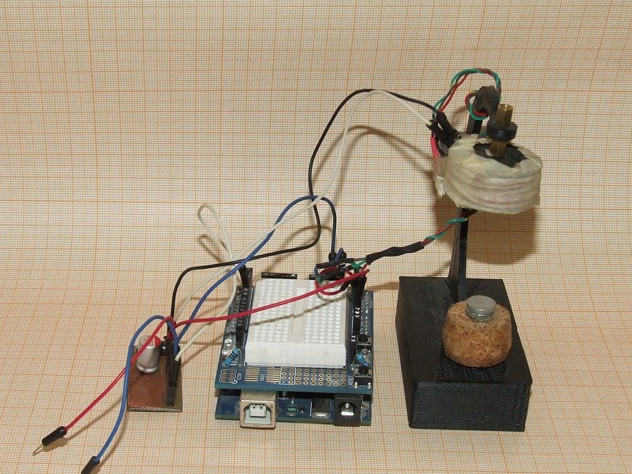
Step Three We assemble the circuit and install all the elements
As a body for homemade work, you can use a piece of timber, to which you need to make a simple bracket for attaching the coil. Electronic the scheme is quite simple, everything can be understood from the picture. Electronics works from a 12V source, and since the sensor needs 5V, it is connected through a special stabilizer, which is already built into the Arduino controller. The maximum device consumes about one ampere. When the top soars, the current consumption is in the range of 0.3-0.4 A.
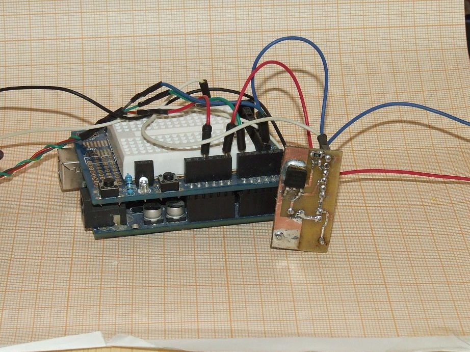
A field effect transistor is used to control the solenoid. The solenoid itself is connected to the outputs of J1, and the first contact of the J2 connector must be connected to the PWM Arduino. The diagram does not show how to connect the Hall sensor to the ADC, but there should not be any problems with this.
Step Four Controller firmware
To program the controller for the necessary actions, firmware is required. The program works very simply. When the values begin to fall outside the permissible range, the system either increases the current to maximum, or completely shuts down. In later versions of the firmware, it became possible to smoothly adjust the voltage on the coil, so the sharp fluctuations of the top stopped.

That's all, the homemade product is ready. At the first start, the device worked, but some flaws were discovered. So, for example, when working for more than 1 minute, the coil and transistor began to get very hot. In this regard, in the future, you need to install a radiator on the transistor or put a more powerful one. The coil will also need to be redone, having come up with a more reliable design than just coils of wire with hot glue.
In order to protect the power source, large capacitors must be supplied to the input circuits. The author’s first 1.5 A power supply burned out after 10 seconds due to strong power surges.
In the future, it is planned to transfer the entire system to a 5V power supply.