
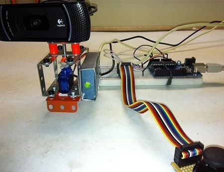
This article will talk about how to use Arduino can control the webcam. More precisely, the control will be a servo drive, which is installed in the frame from the designer on which the webcam will already be attached.
Materials used by the author to create this device:
1) metal constructor
2) cold welding
3) webcam
4) servo
5) LEDs
6) Arduino
8) joystick from PS3
Consider in more detail the design and main points of creating a device for controlling the camera.
Puzzled by the question of how to use such a convenient Arduino platform in addition to standard functions such as flashing lights. Once having a conversation via Skype with a colleague at work, the author came up with an interesting idea. What if you give his colleagues the opportunity to control a webcam and watch what is happening in the office. No sooner said than done, and the author began work on the implementation of this idea.
Initially, the author studied the main materials of articles where a joystick was used to control units created on the Arduino platform. Having understood the material of these articles, the author realized that he could use the old joystick from the PS3 to control the movements of the servo from him.
Starting to build, the author decided to build a frame in which the servo drive and the camera itself will be placed. In order not to complicate the task, the author decided to use the usual metal constructor, which he purchased in a thrift store.
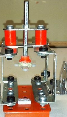
Taking the details of this constructor, it turned out to create such a frame of the future device:
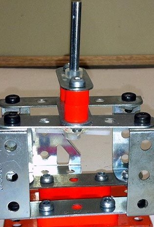
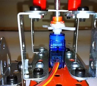
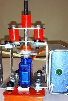
A servo drive was installed inside the frame. As can be seen from the photo, it fit perfectly in the created frame. In order to fix the servo on the frame, the author used double-sided tape. Using cold welding, the servo shaft was connected to the gear, which controls the movement of the platform with the camera.
It is important to ensure that the transmission design is made even so that there is no unnecessary load.
Then the author began to install the webcam. A Logitech camera was used, which is used in the office of the company where the author works. Therefore, due to the fact that the camera does not belong to the author, he did not disassemble it and remove the counterweight, although this would simplify the design of the future device.
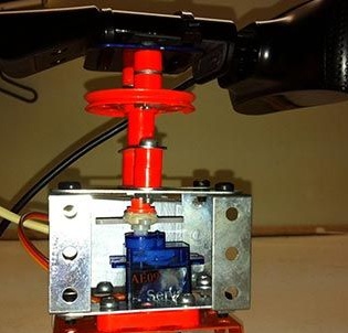
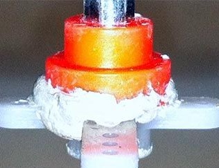
In order to somehow compensate for the weight of the camera and distribute it in the center of the structure, the author used 2 thick gaskets. They allow you to shift the weight of the chamber from the servo shaft to the main frame, and also avoid the pressure of the shaft on the chamber itself.
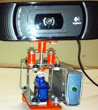
The camera is mounted on a special round platform, which is based on a shaft coming from the servo drive. In this way, camera control is realized by means of a cross transmission.
After the mechanical part of the structure was ready, the author took up it e stuffing.
To begin with, he decided to connect servos and LEDs that will show the status of the system.
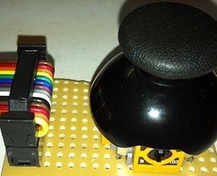
The servo itself has 3 wires: -GND, + 5V and Signal. The author used 9 pins to realize the ability to control the drive. In order to make a drive enable indicator, the author installed a diode that is connected to two wires: + 5V and GND with a resistor on the + 5V line.

Then, based on articles on the Internet, the author prepared a broken joystick from the PS3 to control the drive.
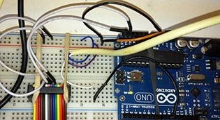
Then the author picked up a program for Arduino, thanks to which it becomes possible to use the joystick and USB port to control the servo. To communicate with a USB port, the author used modem control and an application terminal emulator such as Minicom or Putty.
This program provides several functions for controlling the camera.
In order to install the camera in the center 90 degrees, you must press "m", the camera will also automatically come to this position when the power of the servo is turned on. In order to rotate the camera to the left, it is necessary to press the "F" key, and by pressing the "J" button, the camera is rotated to the right.
You can download the program at the end of the article.
Since the author did not particularly work out the design for the camera rotation device, it began to have a number of some disadvantages.
For example: since the camera is not fixed in the frame, when tilted, it may fall from the platform; since the servo is quite small, the torque of the camera creates additional rotation, which in turn deforms the servo; the holes for the servo shaft are too large, so it is not static and is also subject to stress.
Therefore, in the future, the author wants to slightly upgrade the device as follows: make sure that the camera rotation is controlled by the arrows of the joystick, and not by the buttons; lighten the load on the servo when cornering.