» Electronics » Power supplies »Simple laboratory power supply

Simple laboratory power supply

Simple laboratory power supply

This article will be disassembled in detail and shown on an example of how and from which details you can assemble a simple laboratory power supply. Quite often, radio amateurs encounter the problem of obtaining a certain voltage to power various home-made devices, the author of this also faced the same problem homemade, which just allows you to solve problems of this kind.

Materials and tools that the author used to create the simplest laboratory power supply:

1) A case is required for power supply boards, it can be purchased at electronics stores, or just like the author, you can take it from an unnecessary computer power supply.
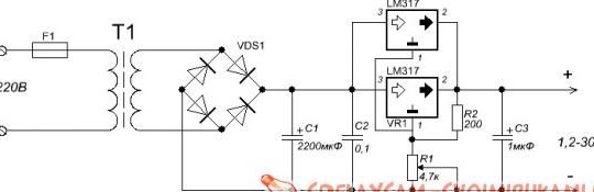
2) A transformer with an output voltage of up to 30 V and a current of 1.5 A is also needed. The power of the transformer should be calculated from which voltage limits you want to make for this power supply.
3) 3A diode bridge
4) electrolytic capacitor 50 V 2200 uF
5) 0.1 μF ceramic capacitor, it will be needed to smooth the ripple.
6) Microcircuit LM317 (the author used 2 such microcircuits in his power supply)
7) Resistor variable 4.7kOhm.
8) Resistor on the 200th 0.5Vat.
9) Ceramic capacitor at 1uF.
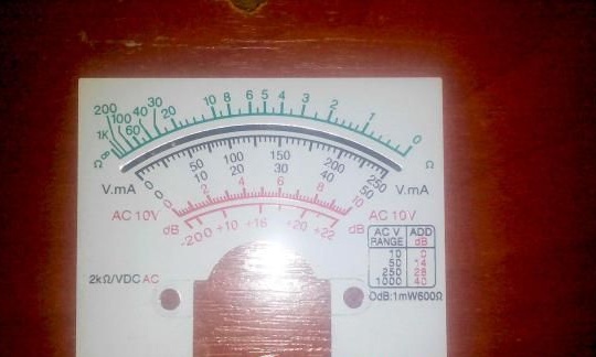
10) The author used his old analog tester as a voltmeter.
11) Textolite and iron chlorine, which will be needed to etch the board.
12) Terminals
13) Wires
14) Blowtorch and soldering supplies.
15) fiberboard or plastic
16) drill

Consider the main stages of creation and design features of the laboratory power supply assembled by the author.


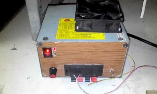
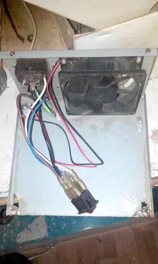
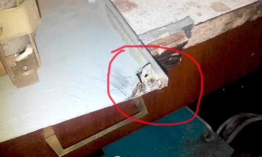
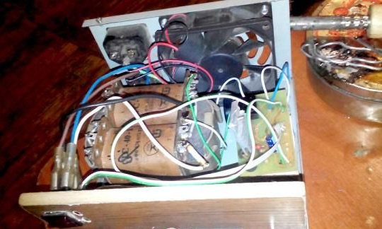
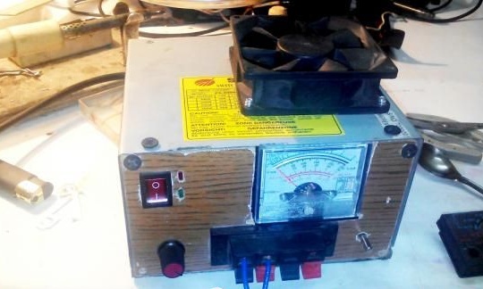
First of all, the author took the case from an unnecessary computer power supply and started preparing it for use as a case for his homemade product. For this, the case was dismantled and the insides were pulled out of it. Then the author sawed off the front panel, from which the wires come out.
All this is shown in the photographs below:

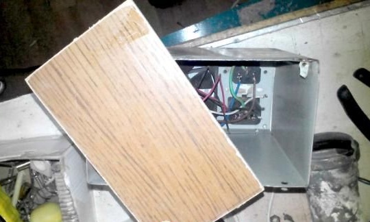
After that, the power supply housing was assembled back. To make the front panel for the laboratory power supply, the author used fiberboard, from which he cut a small board, which was sized for the case. If desired, the panel can also be made of plastic, which can positively affect the appearance of the device.

Further, the author cut off the board mounts from one of the sides and bent them so that it was possible to subsequently fix the prepared front panel to them.


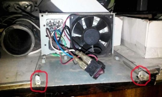
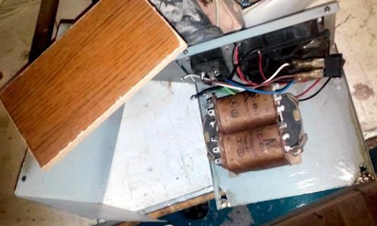
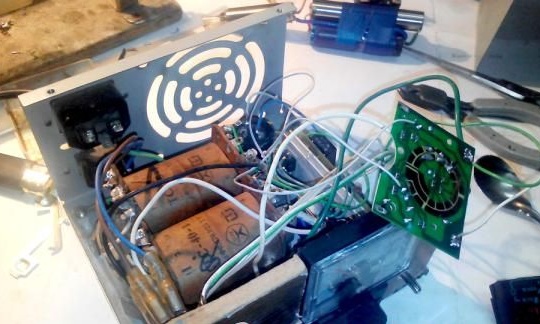
Then the author proceeded to create a place for a transformer. To do this, using a drill, holes were drilled in the lower part of the housing, through which the transformer will be mounted.

After that, the author proceeded to create a board for the device. First, it was necessary to etch it. To do this, the previously printed circuit board was transferred to textolite, after which it was thrown into chlorine for 15 minutes. After the board was etched, the author proceeded to drilling holes and tinning the board.

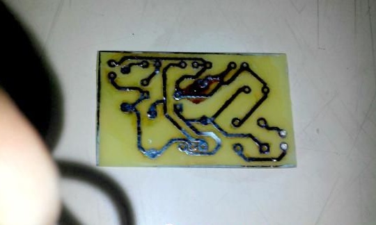
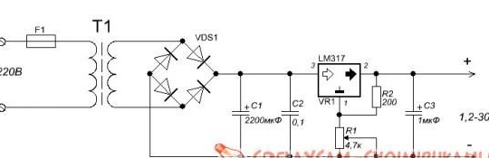
Next, the author proceeded to soldering the elements according to the device diagram, which is given below.

Then the wires were soldered and the entire circuit was assembled into a single housing. It is very important to make the internal arrangement in such a way that the microcircuit is installed on the radiator, since under heavy loads it can decently heat up and quickly become unusable without proper cooling.

In fact, the device is fully assembled and ready for use, but first you need to conduct tests to make sure the power supply is working correctly and if necessary, eliminate its shortcomings.

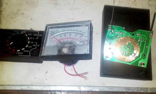
Further, the author began to remake the old tester into a voltmeter. To do this, the author simply cut off the indicator itself from the plastic case, after which
set a jumper on the tester board in the range of 50 V. Then the author cut a hole in the front panel of the device for the resulting voltmeter and connected all the necessary wires. After that, the board was isolated.

After the final assembly of the case, the author decided to install a fan on top of the device in order to blow the radiator and cool the microcircuit attached to it.

After all these actions, we got a good laboratory power supply with a fairly simple design and assembly.
7
8.6
6.6

Add a comment

    • smilesmilesxaxaokdontknowyahoonea
      bossscratchfoolyesyes-yesaggressivesecret
      sorrydancedance2dance3pardonhelpdrinks
      stopfriendsgoodgoodgoodwhistleswoontongue
      smokeclappingcraydeclarederisivedon-t_mentiondownload
      heatirefullaugh1mdameetingmoskingnegative
      not_ipopcornpunishreadscarescaressearch
      tauntthank_youthisto_clueumnikacuteagree
      badbeeeblack_eyeblum3blushboastboredom
      censoredpleasantrysecret2threatenvictoryyusun_bespectacled
      shokrespektlolprevedwelcomekrutoyya_za
      ya_dobryihelperne_huliganne_othodifludbanclose
13 comments
Skybark
Quote: Ivan_Pokhmelev
5. The board is incorrectly wired, as a result of which it is extremely difficult to put a radiator on the microcircuit normally.

Absolutely agree. Moreover, primitively expanding the LMc, we get And the ability to mount the radiator, And a simpler board pattern. :about)
Quote: Ivan_Pokhmelev
Quote: ya.fan2000
In general, I had in mind the concept of a BP, and not the process of its assembly by the author.
You never know what you mean there. Wrote not this, but
What's wrong with this PSU

If the circuit diagram is specific, then this circuit NOT laboratory power supply. Moreover, this, strictly speaking, is not even a principle, but a functional diagram, since the connection of the transformer windings is not indicated. But, even so loudly calling his PSU, the author could not make it any decent decent simple power supply. Incorrectly selected transformer, terrible construct. In short - is not subject to revision.

Well, the author so called his design, no offense will be told to him, based on his knowledge of electronics. For him, let this PSU remain laboratory. And the execution of the construction is, to put it mildly, not very, completely agree with this.
Quote: ya.fan2000
In general, I had in mind the concept of a BP, and not the process of its assembly by the author.
You never know what you mean there. Wrote not this, but
What's wrong with this PSU

If the circuit diagram is specific, then this circuit NOT laboratory power supply. Moreover, this, strictly speaking, is not even a principle, but a functional diagram, since the connection of the transformer windings is not indicated. But, even so loudly calling his PSU, the author could not make it any decent decent simple power supply. Incorrectly selected transformer, terrible construct. In short - is not subject to revision.
Quote: Ivan_Pokhmelev
Quote: ya.fan2000
What is wrong in this BP except for the wrong, in your opinion, article title?
1. The wrong name is not in my opinion, but in fact how it was done.
2. It is not written how the transformer is turned on. There are big suspicions that it is wrong.
3. Where does the fan come from?
4. The location of the parts was not thought out, as a result of which the fan was mounted on the cover.
5. The board is incorrectly wired, as a result of which it is extremely difficult to put a radiator on the microcircuit normally.
6. It is written "LM317 microcircuit (the author used 2 such microcircuits in his power supply unit)", but where the author of the second IC was written is not written.

Actually, I had in mind the PSU schematic diagram, and not the author’s assembly process.
Quote: ya.fan2000
What is wrong in this BP except for the wrong, in your opinion, article title?
1. The wrong name is not in my opinion, but in fact how it was done.
2. It is not written how the transformer is turned on. There are big suspicions that it is wrong.
3. Where does the fan come from?
4. The location of the parts was not thought out, as a result of which the fan was mounted on the cover.
5. The board is incorrectly wired, as a result of which it is extremely difficult to put a radiator on the microcircuit normally.
6. It is written "LM317 microcircuit (the author used 2 such microcircuits in his power supply unit)", but where the author of the second IC was written is not written.
Quote: Ivan_Pokhmelev
Do you want to make a laboratory block (as loudly stated in the title) a block out of this? It must not be modified, but done from scratch and correctly.

What is wrong in this BP except for the wrong, in your opinion, article title?
Do you want to make a laboratory block (as loudly stated in the title) a block out of this? It must not be modified, but done from scratch and correctly.
Quote: Ivan_Pokhmelev
Porridge from the ax is called. ;)

This is called device refinement.
Porridge from the ax is called. ;)
It does not hurt in this PSU to stir up current protection, and put the LM-ku on a good radiator.
Quote: popvovka
Maybe a person is just learning. Maybe for the first time writing an article, worried ...

He doesn’t write, but writes off (already 183 times). Why worry then?
Or maybe he is a foreigner and does not understand the Russian language? He translated it two times (back and forth), and that’s srach.
Nick then "NORTH" with him, is not translated into Russian ?!)))
dontknow
But "minus" .... weak little people, mind !!!
Maybe a person is just learning. Maybe for the first time writing an article, worried ...
ceramic capacitor at 0.1 microfarads, it will be needed to smooth the ripple.
Not ripple, but high-frequency interference.
... iron chlorine,
What kind of beast is this? ;)
Blowtorch and soldering supplies.
You can not read further ... ((

We advise you to read:

Hand it for the smartphone ...