In the stage props of the comedy theater, a powerful adjustable portable source of directional air was needed.
Also, the weight needs a minimum, battery life, for several minutes, a charger.
Various automobile fans (stove fans, radiator fans) were tested, but they were too powerful and very large.
Different toys are considered, but their power, on the contrary, is too small.
Electric hair dryers incorporate a low-voltage electric motor, but they did not fit in size and noise level
Households did not fit due to high-voltage power, it is difficult to make autonomous.
All kinds of computer and other coolers also did not fit due to insufficient power.
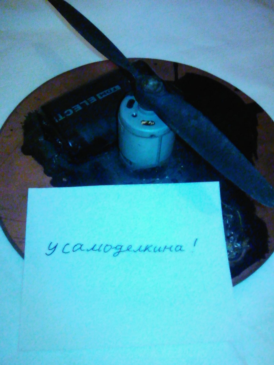
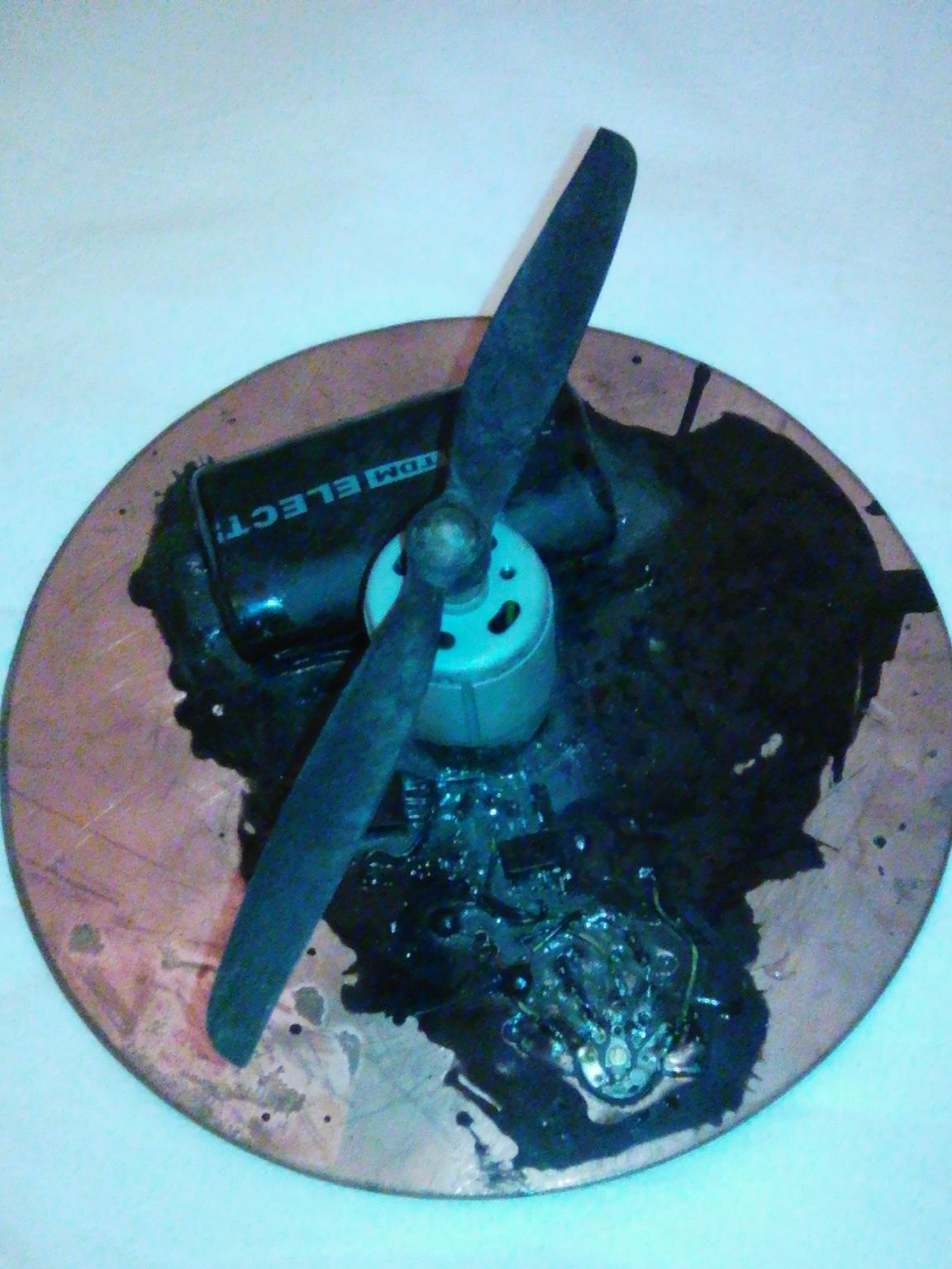
After several test copies, such a fan was made.
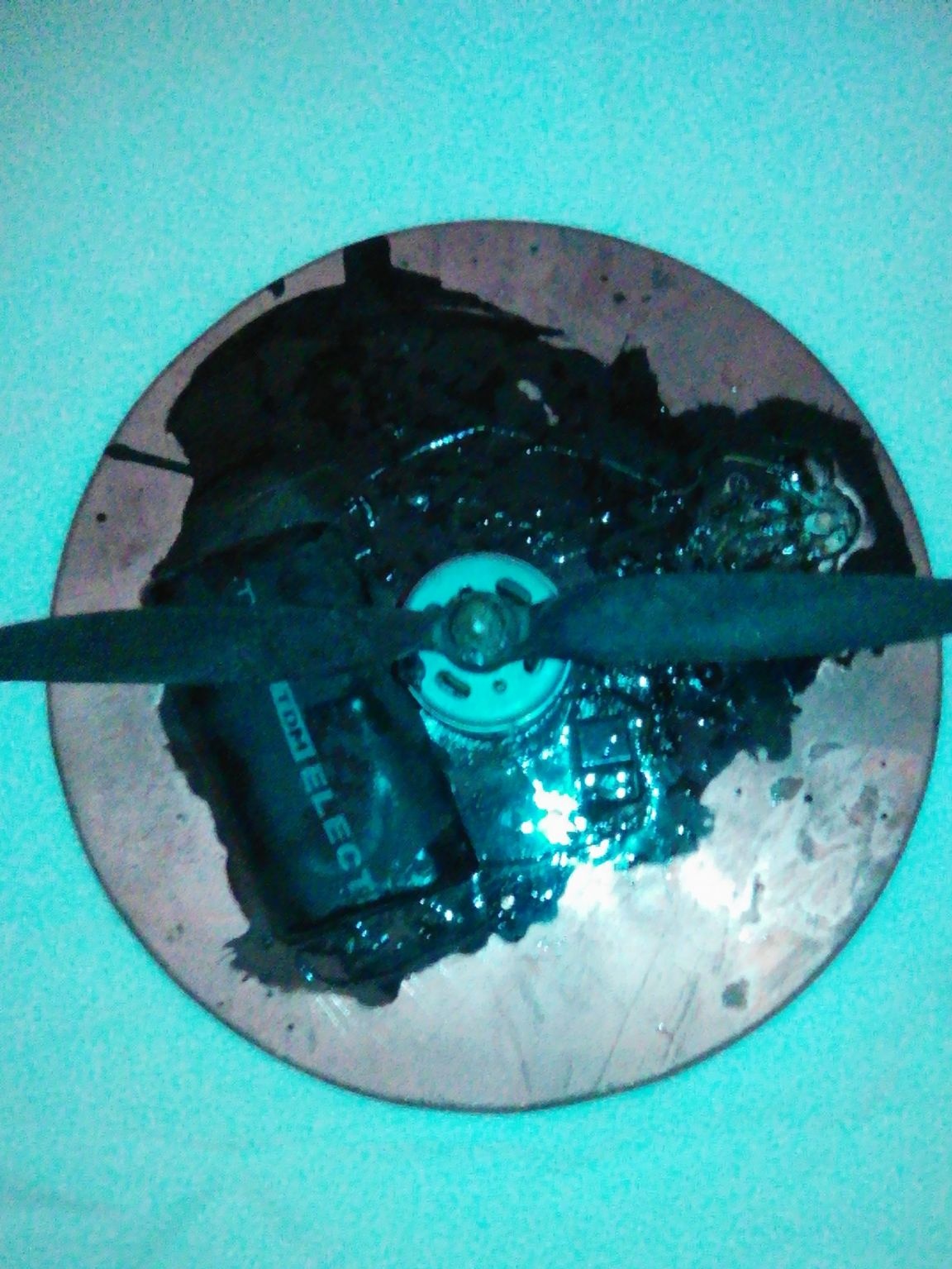
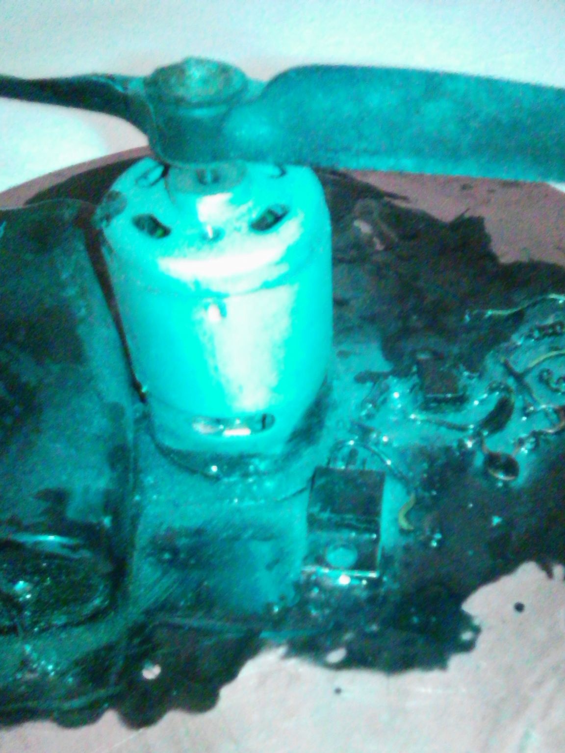
The engine and propeller are taken from radio-controlled electric aircraft. It also took some experimenting with different screws for maximum impact and minimal noise.
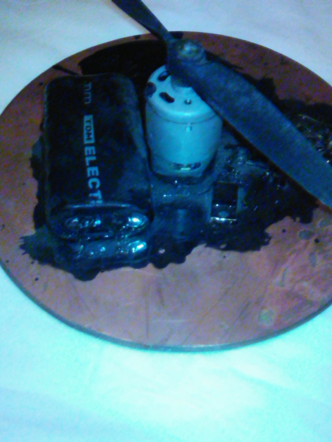
2000mAM / h lithium cylindrical batteries, two pieces connected in series.
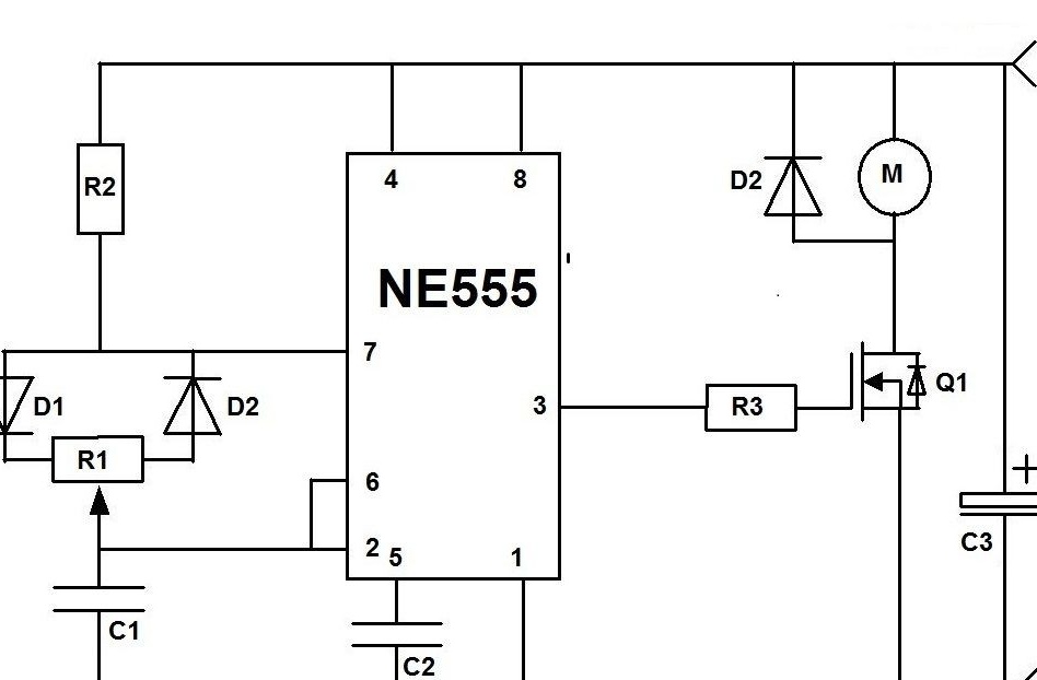
The PWM speed controller is made according to the well-known classic circuit on the NE555 chip. See picture.
For better adhesion, files are applied to the motor shaft with a file and the screw is glued with epoxy to the motor shaft.
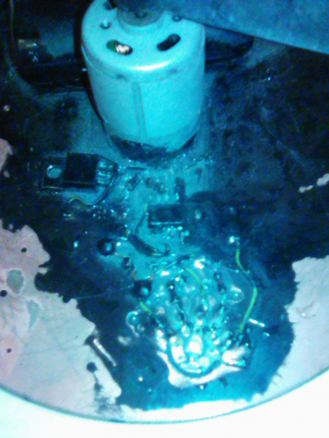
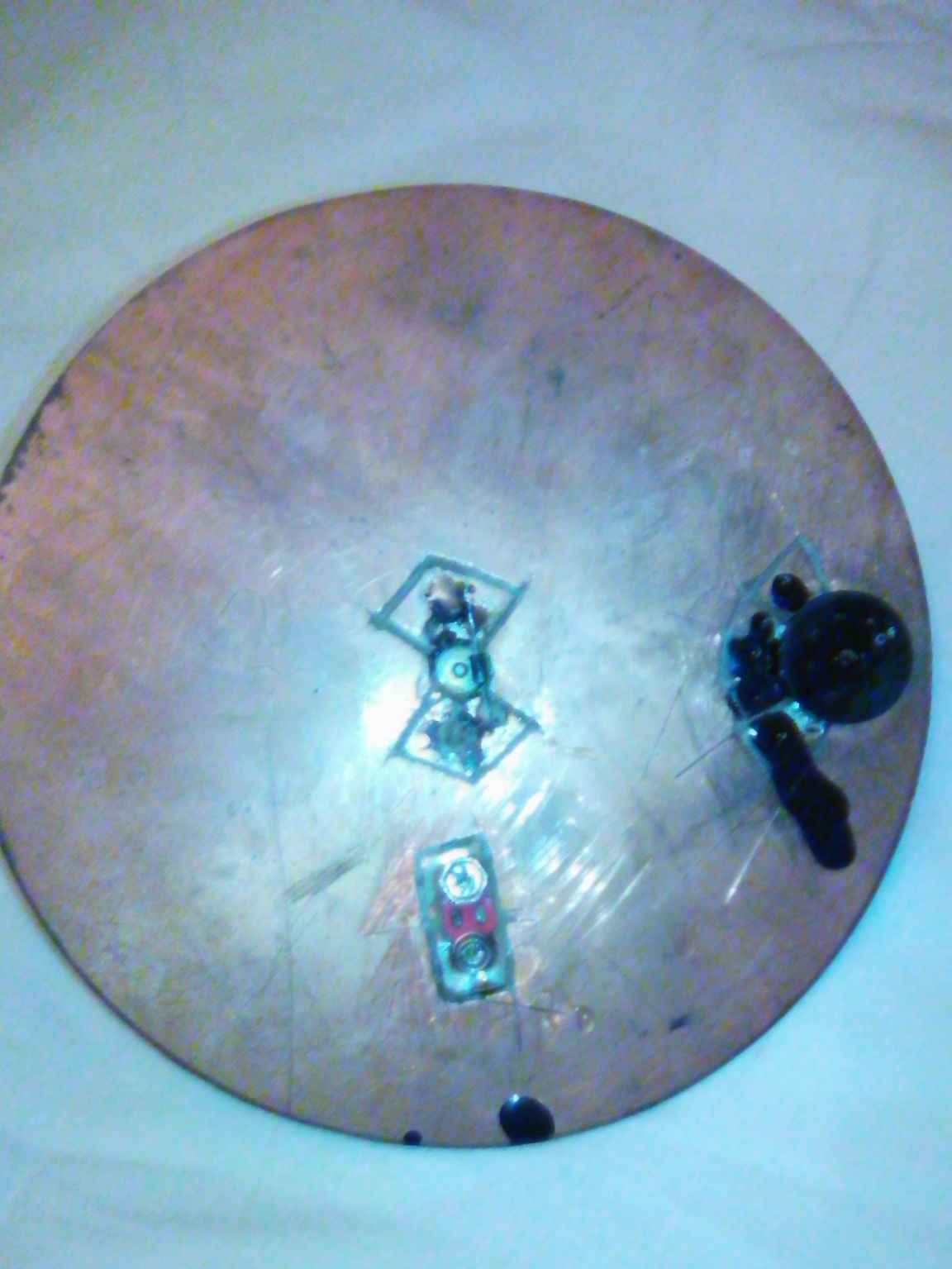
A circle is cut out of foil fiberglass. It is a very durable material and easy to handle. Drilled holes for mounting an electric motor and a variable resistor. In foil, cut tracks for electrical connections.
An electric motor is glued to the back with epoxy. Through the holes pass the electrical terminals of the electric motor, which on the other hand are soldered to the respective tracks.
The speed controller is made according to the scheme shown in Fig. The microcircuit knives are bent to the sides so everything is assembled by surface mounting.
An IRL2505 insulated gate field effect transistor is installed as a power switch
This circuit has multiple power reserves. No transistor heating.
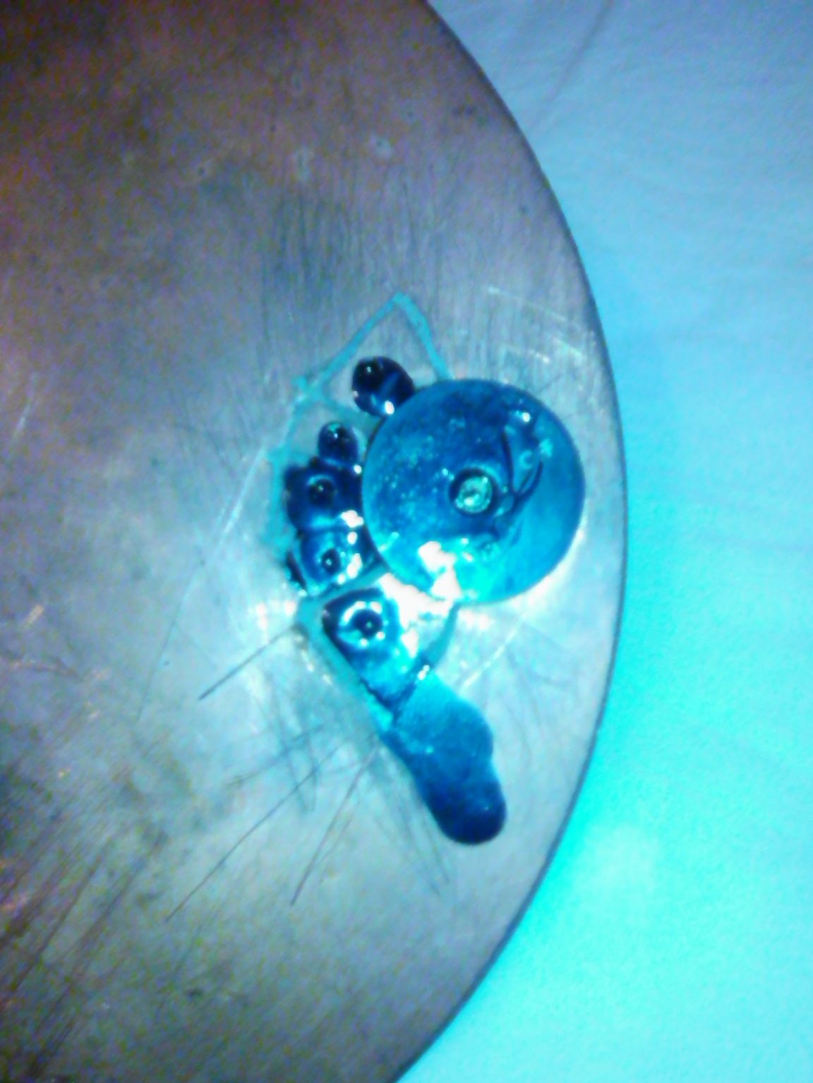
A small-sized variable resistor with a switch and a side wheel from an old portable radio. Also installed side by side in the corresponding hole. The peculiarity of the inclusion of this element is that the switch contacts disconnect the voltage only from the NE555 control chip, after which the power switch is de-energized and closed. Thus, a small control current passes through the switch contacts, and not the current of the entire device.
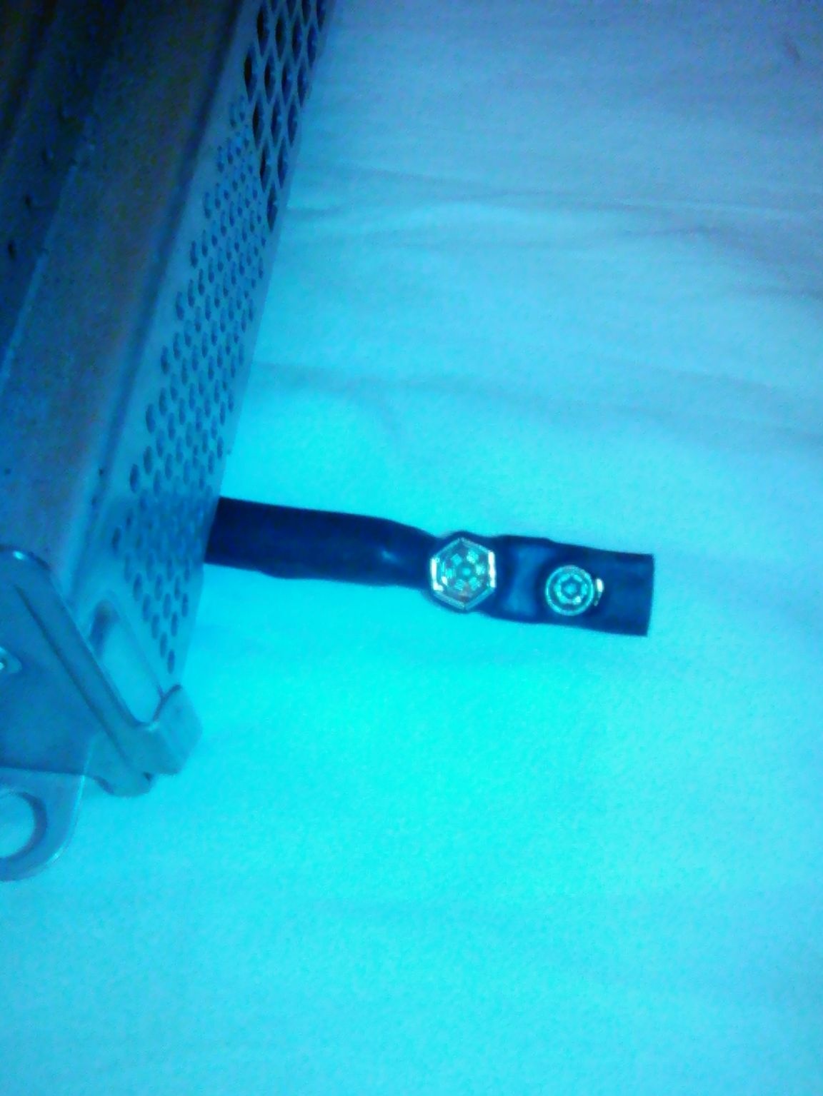
Heat-shrink tubing is attached to the batteries, lined with hot air and glued. The battery leads are soldered to the corresponding tracks.
On the other hand there is a connector for charging batteries. After several tests, the crown battery connector was used. The main advantage is that if the cord of the charger is pulled (for example, it is hooked naked), the connector will be disconnected and the cord will not be damaged, other devices will not be damaged. The operation turned out to be very convenient. Saved many times.
All details for giving mechanical strength are filled in with a technical compound.
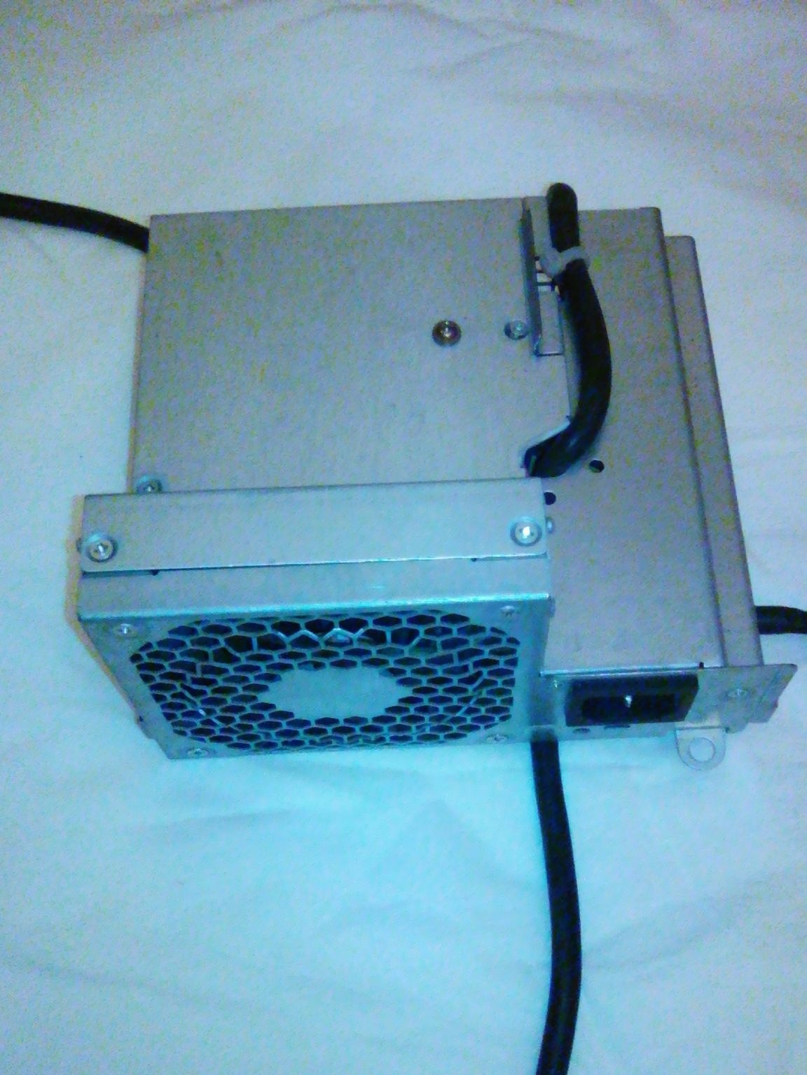
A computer power supply was used as a charger. It is very reliable, not afraid of overloads and is easily accessible, and also very reliable.
A voltage of 8.2 V was selected for the charge. This voltage is not much lower than the maximum on the batteries. Made to extend battery life. The battery capacity naturally decreased, but it is enough with a margin.
All unnecessary wires are removed from the unit. The green manager is connected to the general for continuous operation.
Since the batteries require charging voltage of 8.2 V, and the standard voltage in this power supply unit is 5, 3.3 and 12 V, the unit is equipped with a step-down stabilizer on the LM317 chip in a standard connection. See picture.
The microcircuit operates in linear mode and generates a lot of heat. She installed it on one of the radiators near the fan of the power supply through an insulating heat-conducting gasket. During operation, overheating was not detected.
Resistor R2 set the required voltage.
With such a charge, there is no danger of recharging the batteries.
In the future, it is planned to install a lattice wired casing on this device to increase safety.