

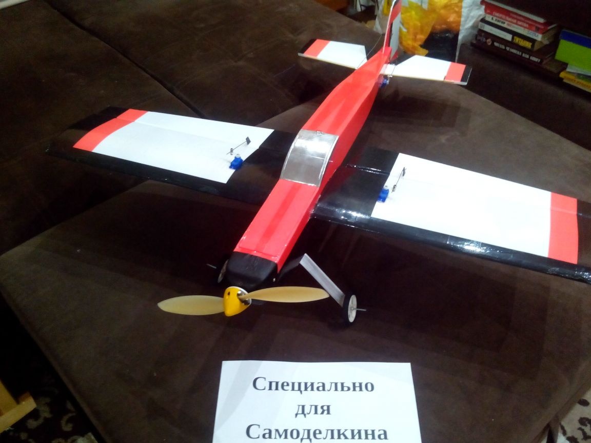
Next will be a detailed article about the manufacture of this model. The aircraft is very easy to manufacture and maintainable. Moreover, electronics, which is used in it, is suitable for trainer models, which makes it possible to switch from a “plane trainer” to “aerobatics” without extra costs.
Drawing a model in Excel format, just print and glue it. Or even just draw on the ceiling with a marker on the ruler.
Materials:
- Ceiling tile
- Penoplex
- Colorful tape
- Wooden rulers
- Bamboo sticks and skewers
- Thin plywood
- steel wire
- Tin
- Docking tape for linoleum
- Glue for ceiling tiles
- PVA glue
- Epoxy adhesive
- Velcro
Instruments:
- Stationery knife
- Metal ruler
- Square
- CD marker
- scissors
- Jigsaw
- Sandpaper
- Needle files
- Clothespins
- Syringe for glue
- electrical tape
- Pliers
- Screwdriver with drills
- Thermogun
- Iron
Electronics:
Wheels - and
Step 1. Small changes in the drawings.
Since this model I did it twice, I will give a list of the changes that I made to the design.
1. The fuselage expanded by 1 cm and did not narrow the nose so that all the electronics and the battery fit inside.
2. The lower part of the fuselage was made of foam (2 cm thick) to increase the strength of the structure.
3. The wing is moved 15 mm closer to the tail so that the center of gravity is in the right place. And the wing itself will be without ribs - with several spars of different thicknesses.
4. The chassis in the first version was pulled out twice, and therefore it was decided to strengthen the mounting position of the landing gear.
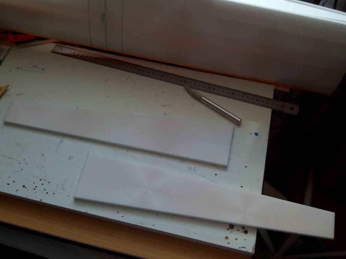
Step 2. Making a wing.
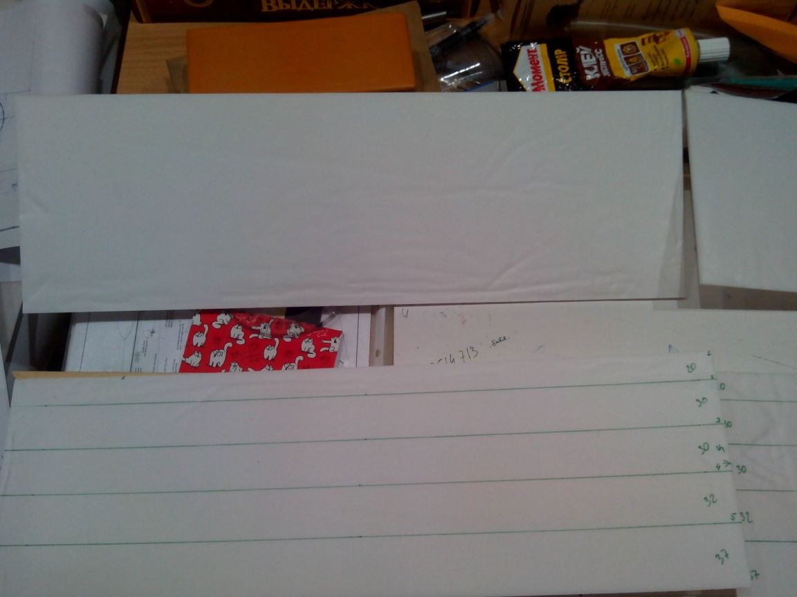
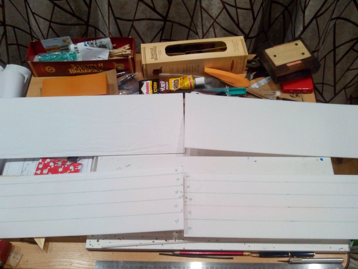
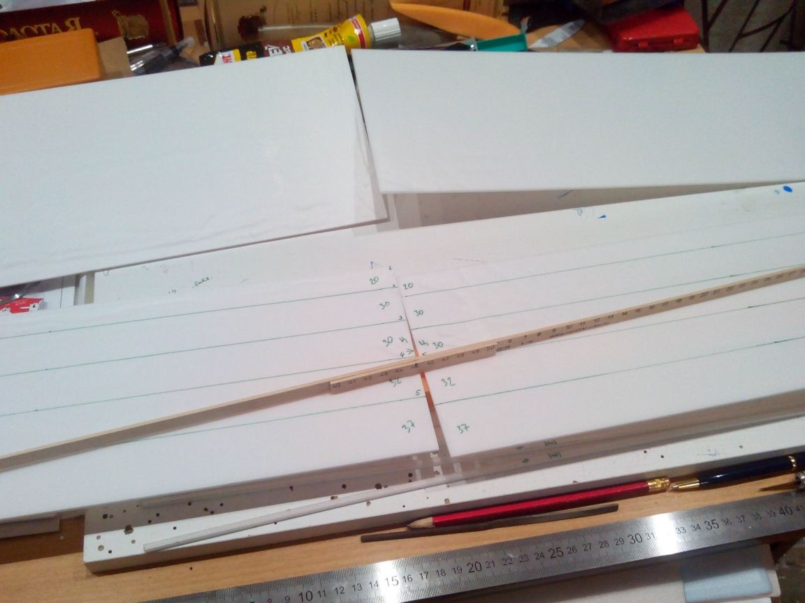
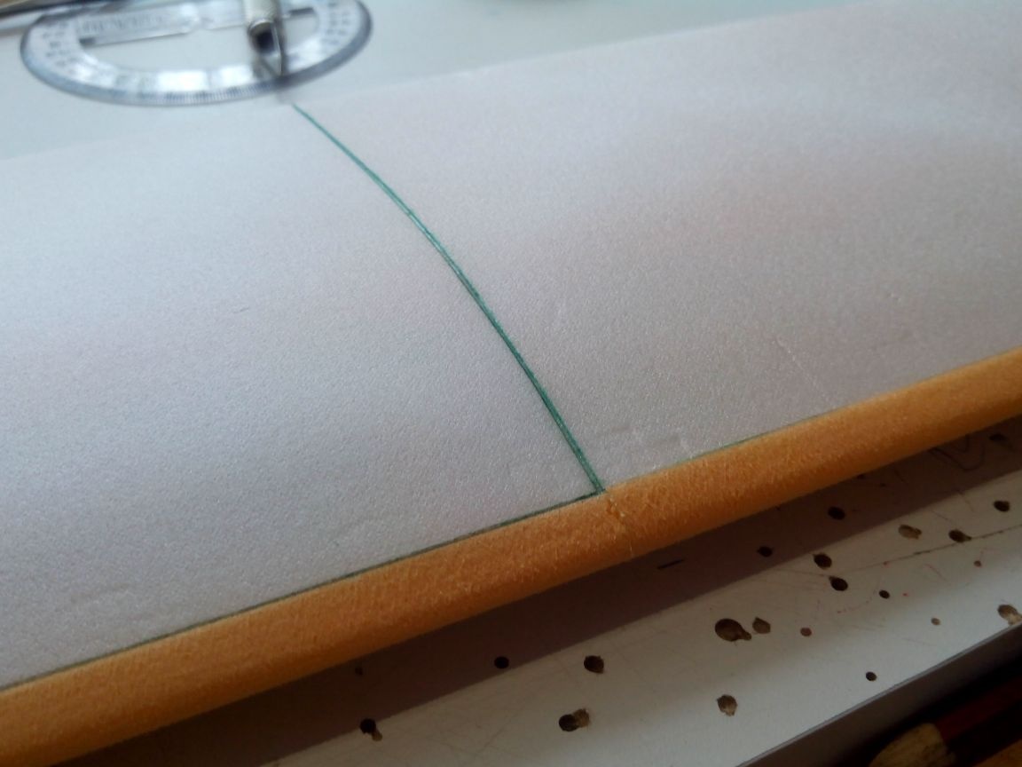
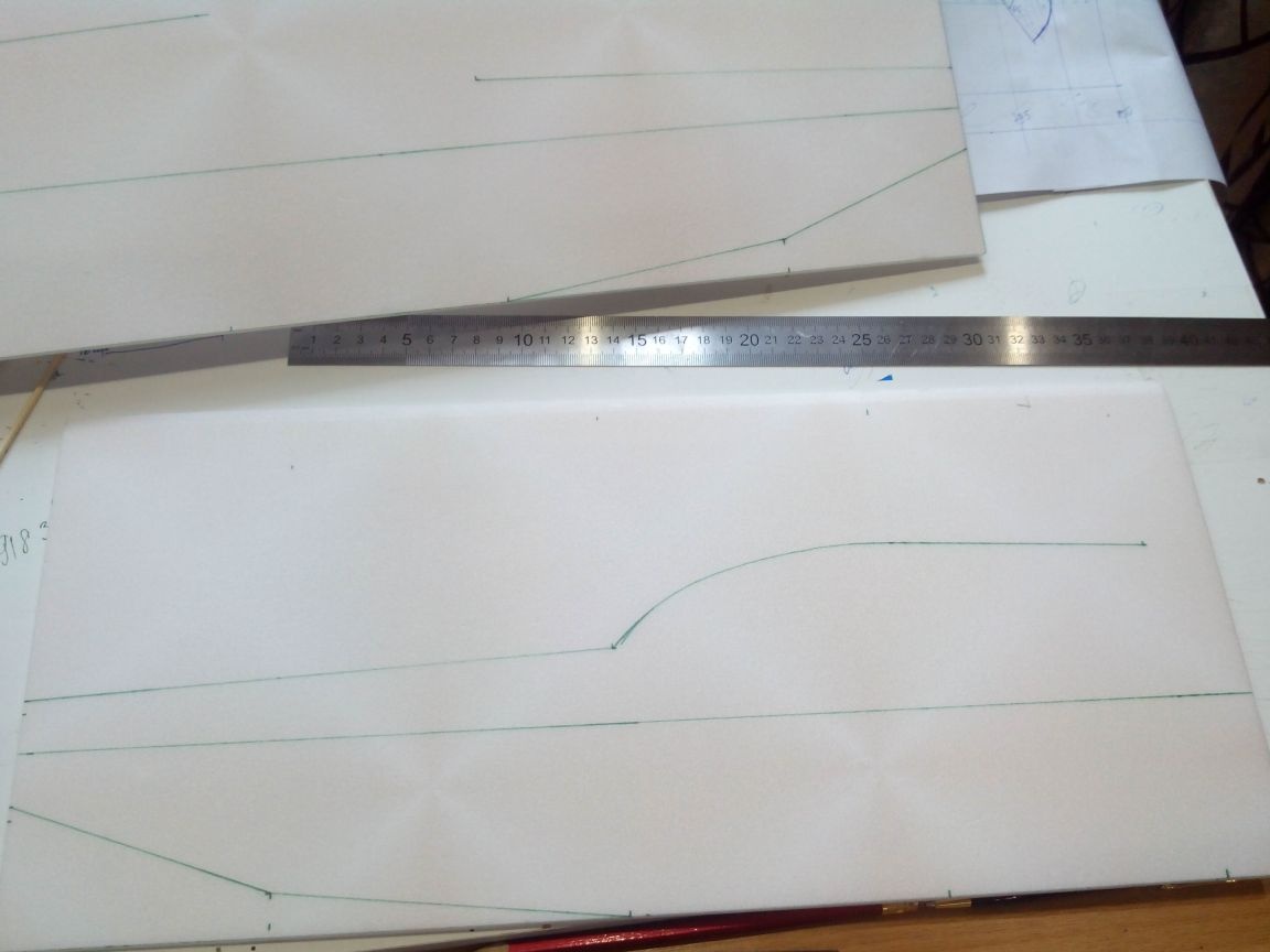
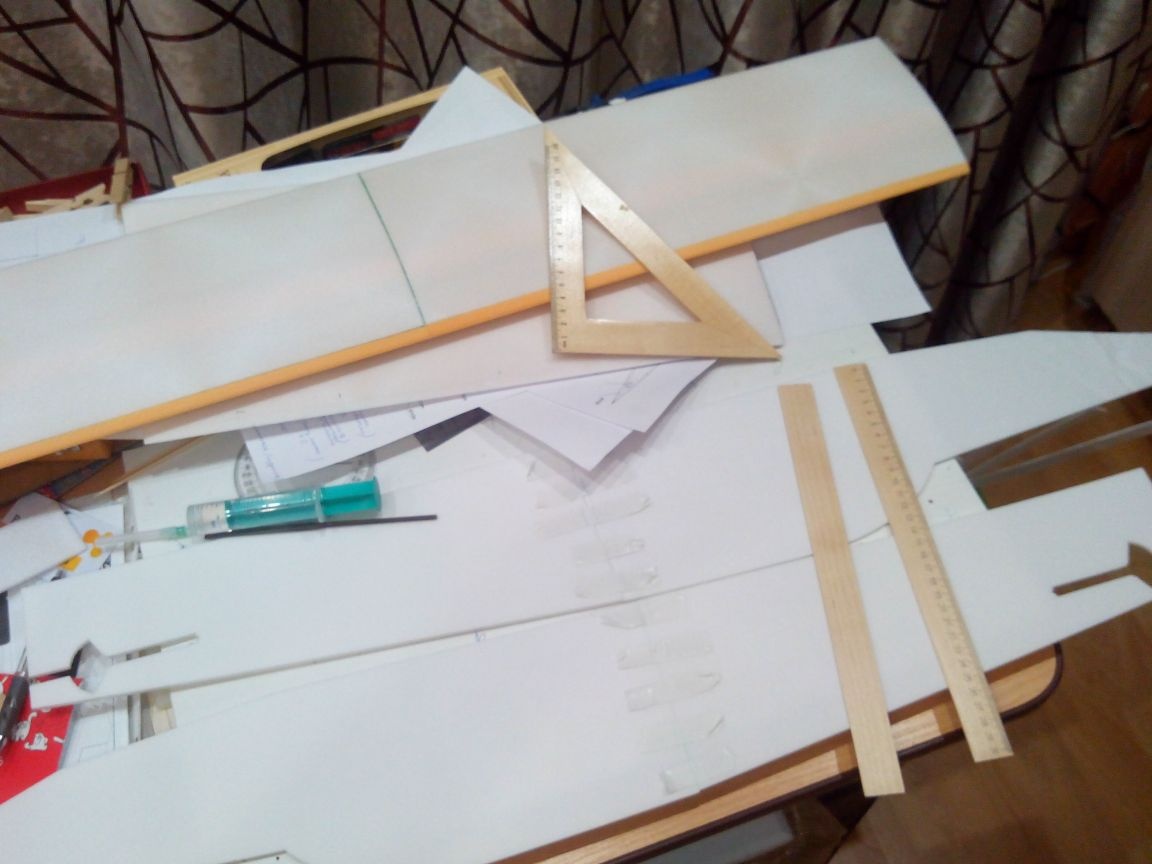
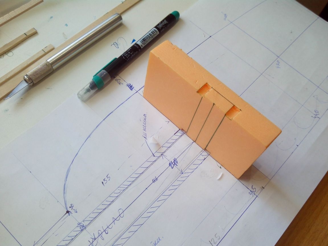
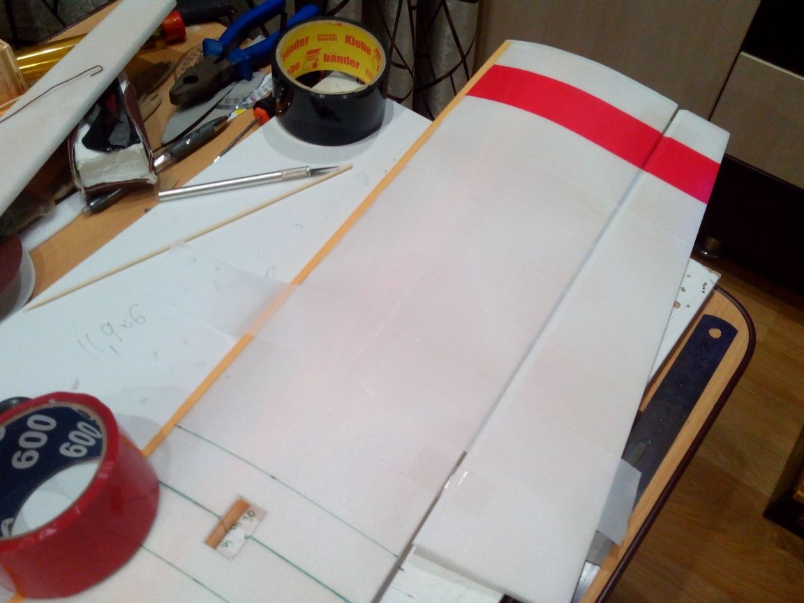
We mark on the ceiling a marker for disks and cut out with a cutter four rectangles with dimensions of 155x470 mm. On the inside, draw lines along which the side members will be glued. The distances between them are visible in the photo, but depending on which wing profile to choose.
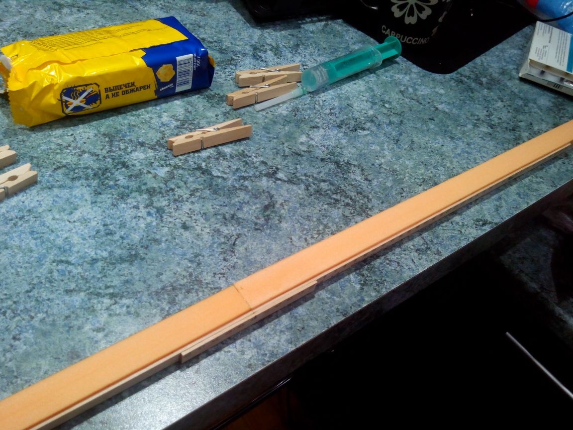
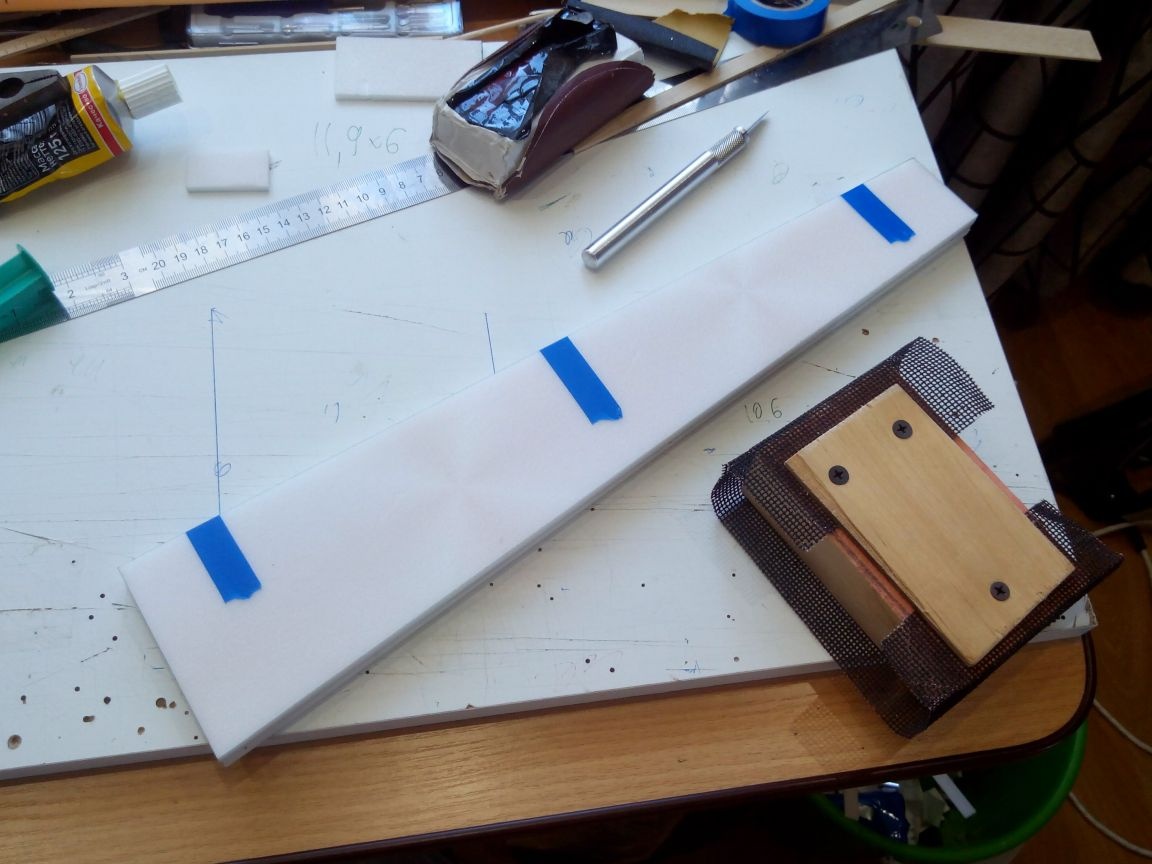
From the scraps of the ceiling we cut the side members. The central one is made of penoplex (orange in the photo)
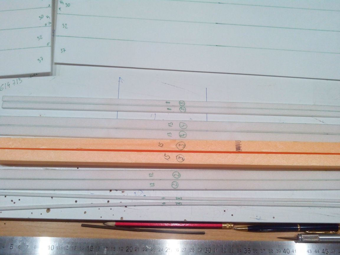
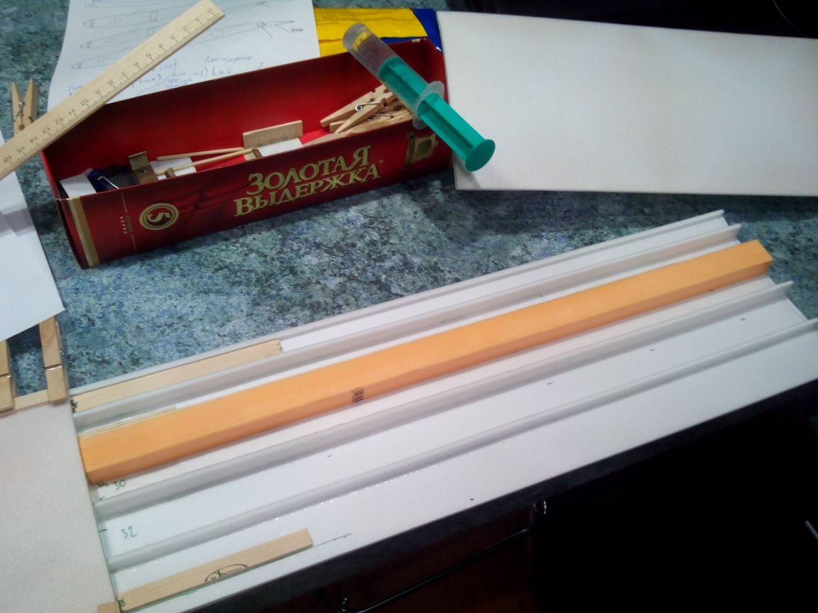
Glue the wooden spar glued from the ruler to the foam-palleted spar (length 800 mm).
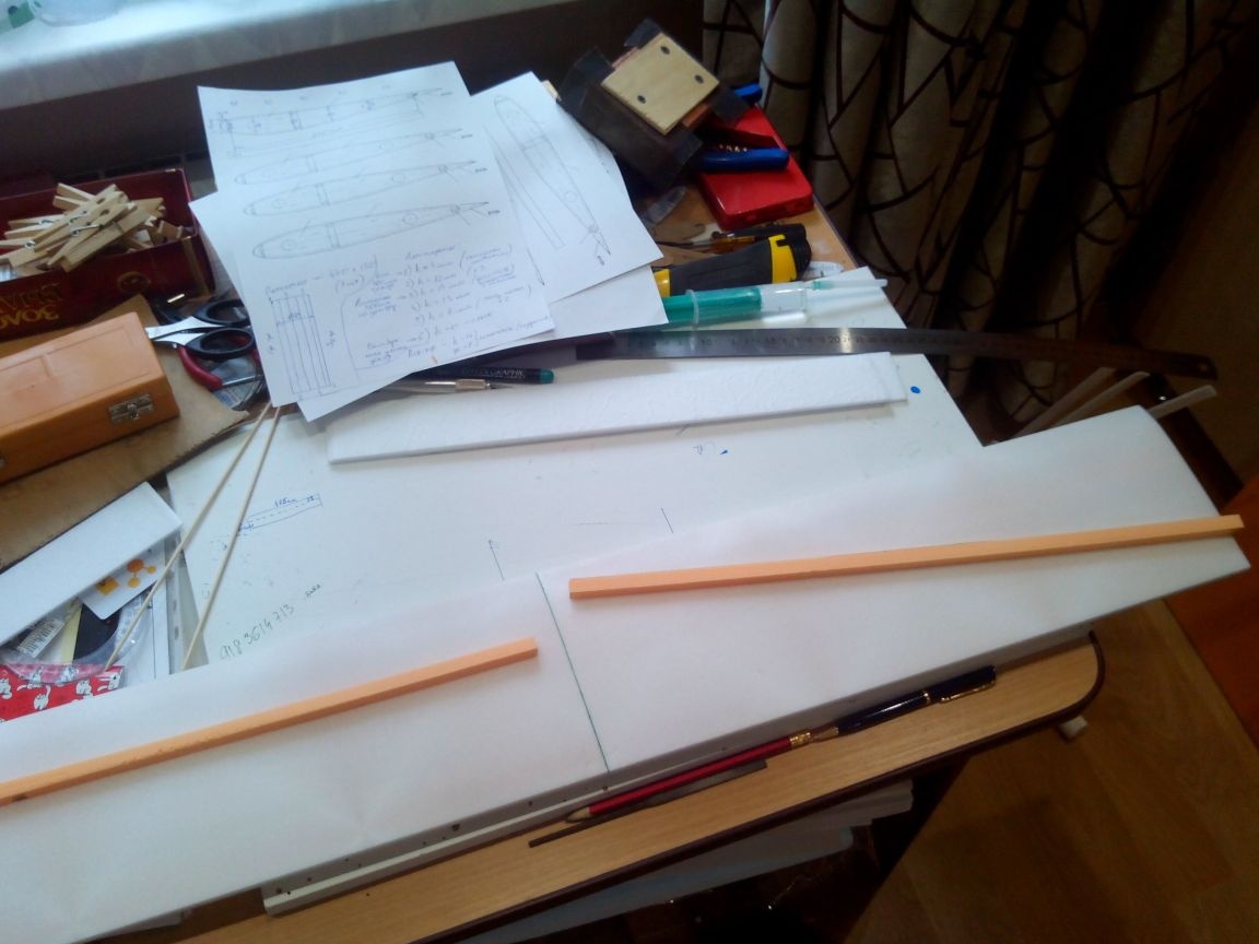
On a flat surface we glue the lower parts of the wing consoles, glue the spars from the ceiling and foam, we strengthen the joint of the halves from the inside with small (about 200 mm) pieces of the ruler along the front and rear edges and glue the upper parts.
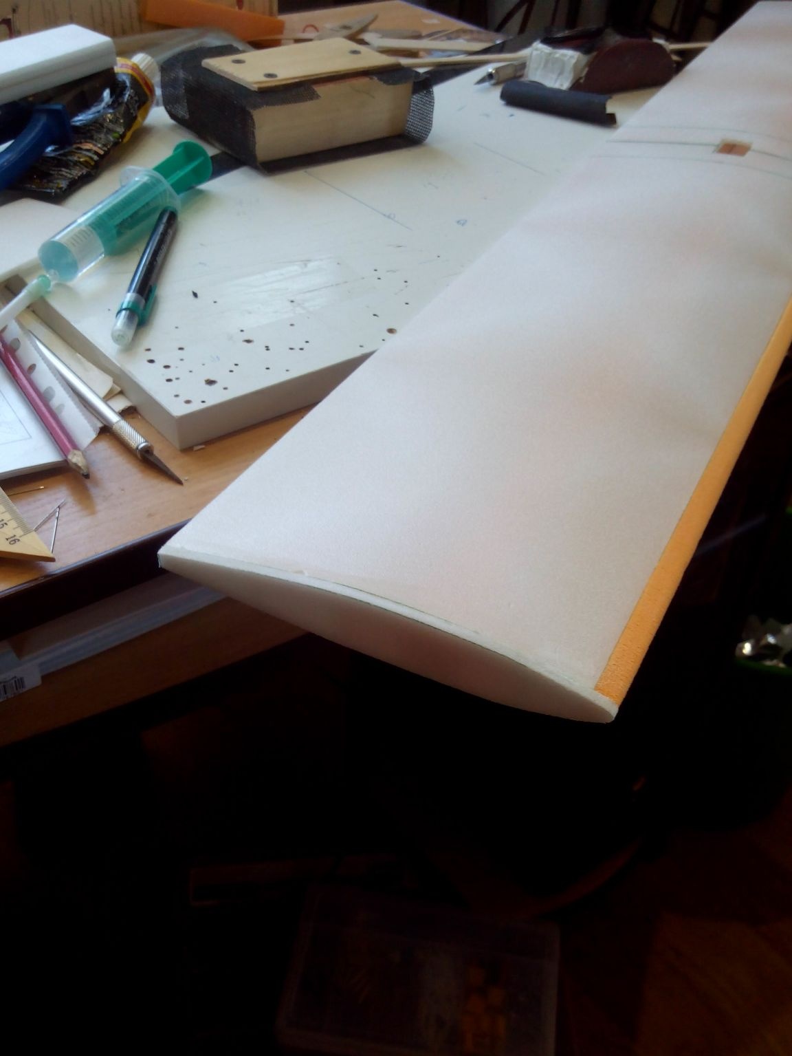
The leading edge blanks are made of foam (or from the ceiling) and glued to the wing.
After the glue dries, the front edge is treated with rough sandpaper and ground finely.
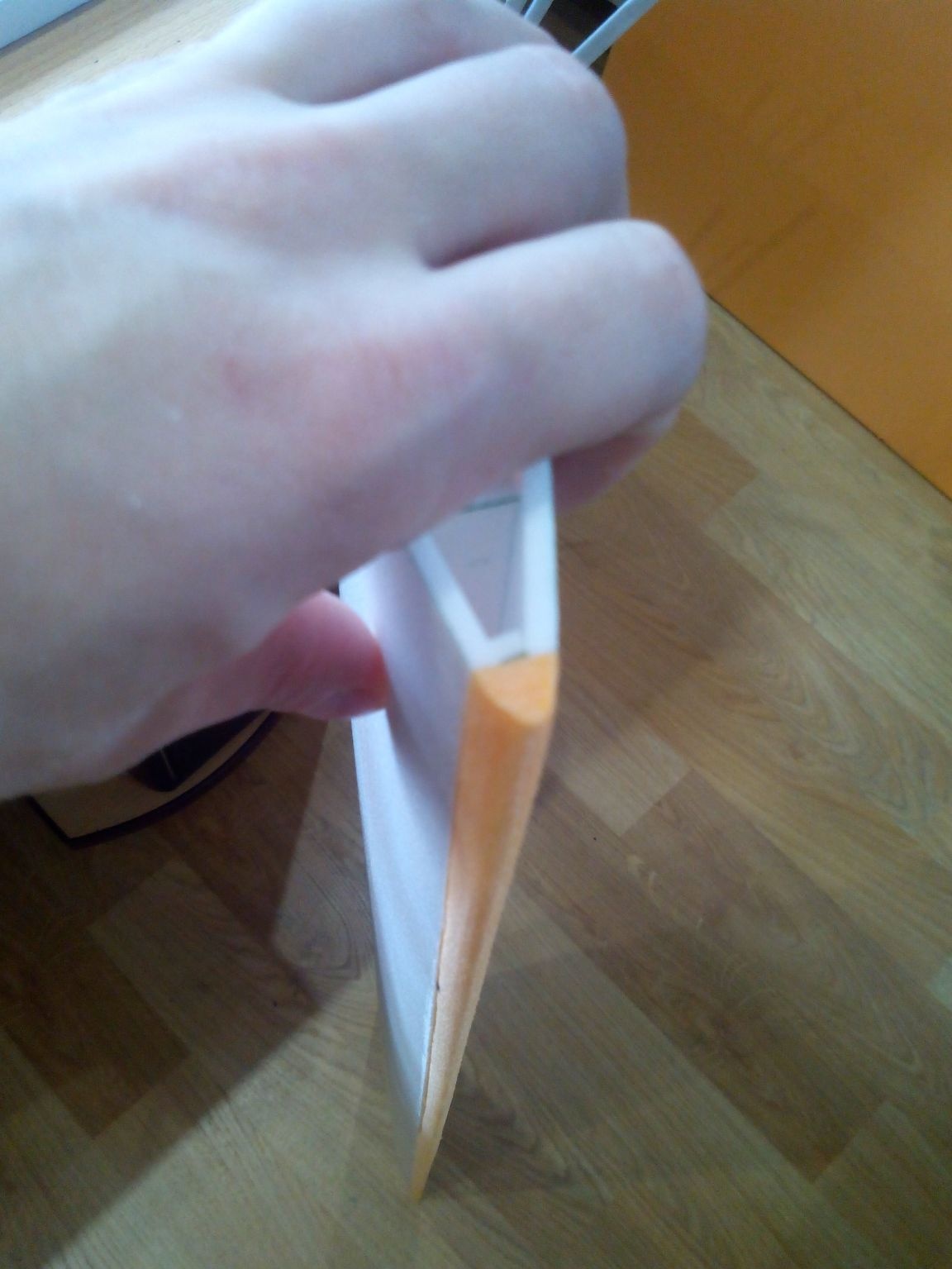
The wingtips are made from ceiling tiles and glued. Then we process sandpaper.
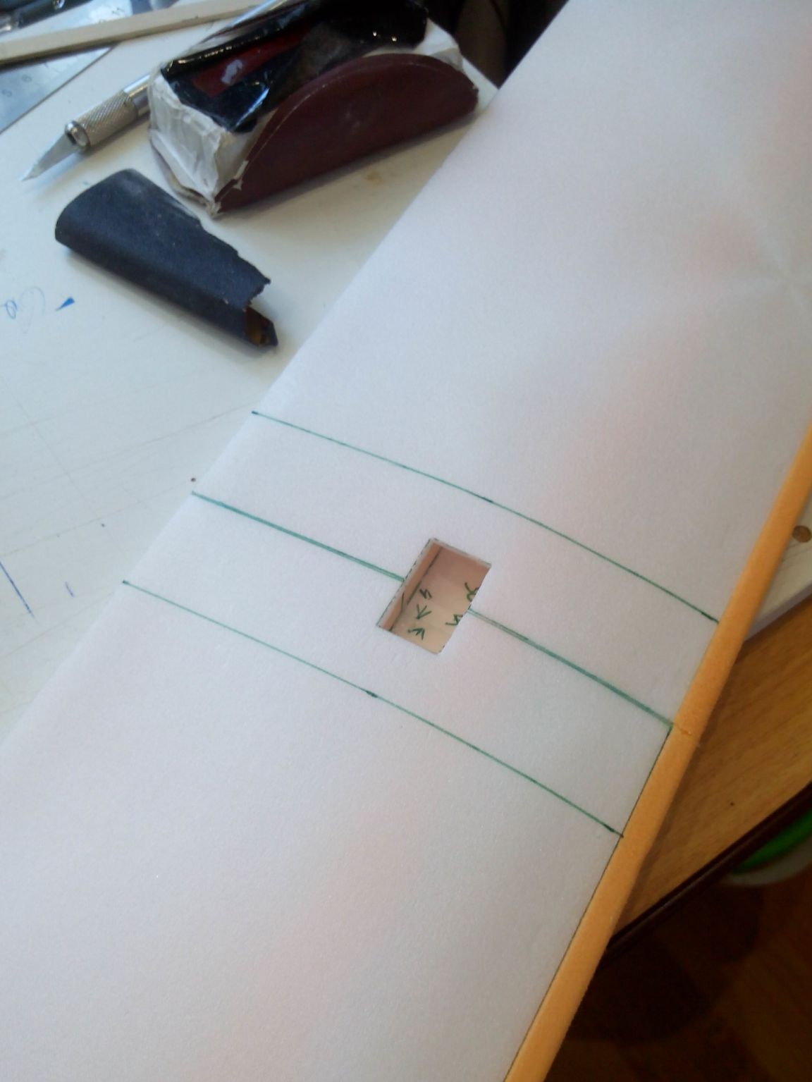
In the center of the wing near the central side member, we cut a hole on one side for outputting wires to the ailerons servos. The smaller the hole, the higher the strength of the wing will be, and therefore the main thing is not to overdo it.
According to the drawing, we cut the aileron blanks, they are made of two layers of the ceiling, and we glue the halves together.
To get the same ailerons we connect them to each other with electrical tape and process the edges with sandpaper.
Then, on each individually, we skin the edge along which the aileron will connect to the wing, at an angle of 45 degrees from two sides.
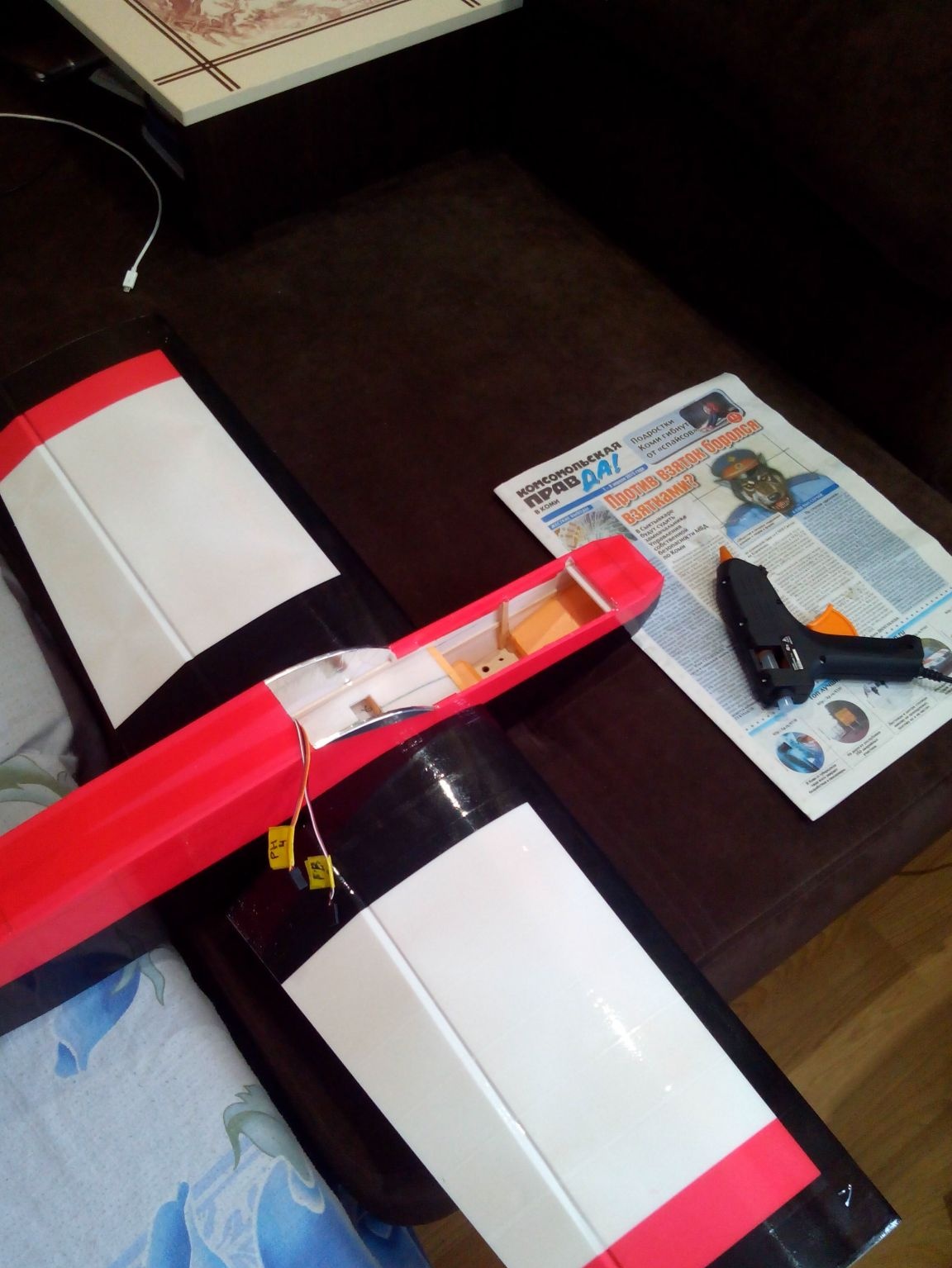
Ailerons will be attached to the wing on tape. So that you can then insert the wing into the fuselage, we hang so far only one aileron. After that, the wing can be postponed and proceed to the fuselage.
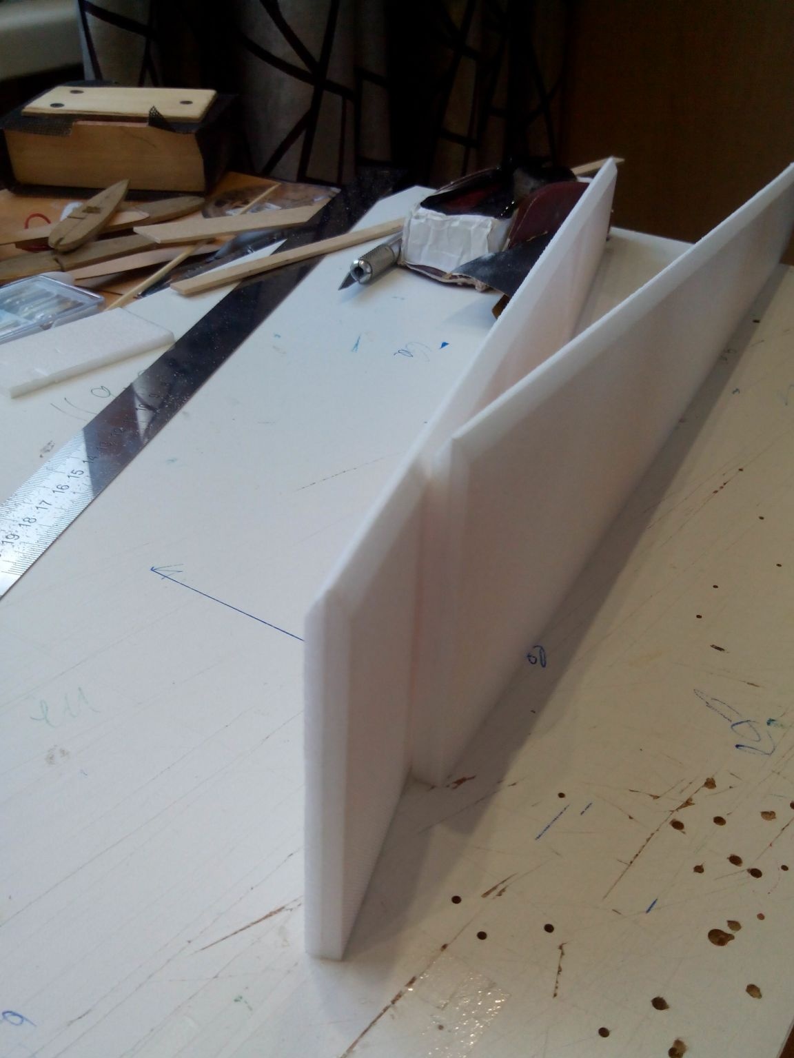
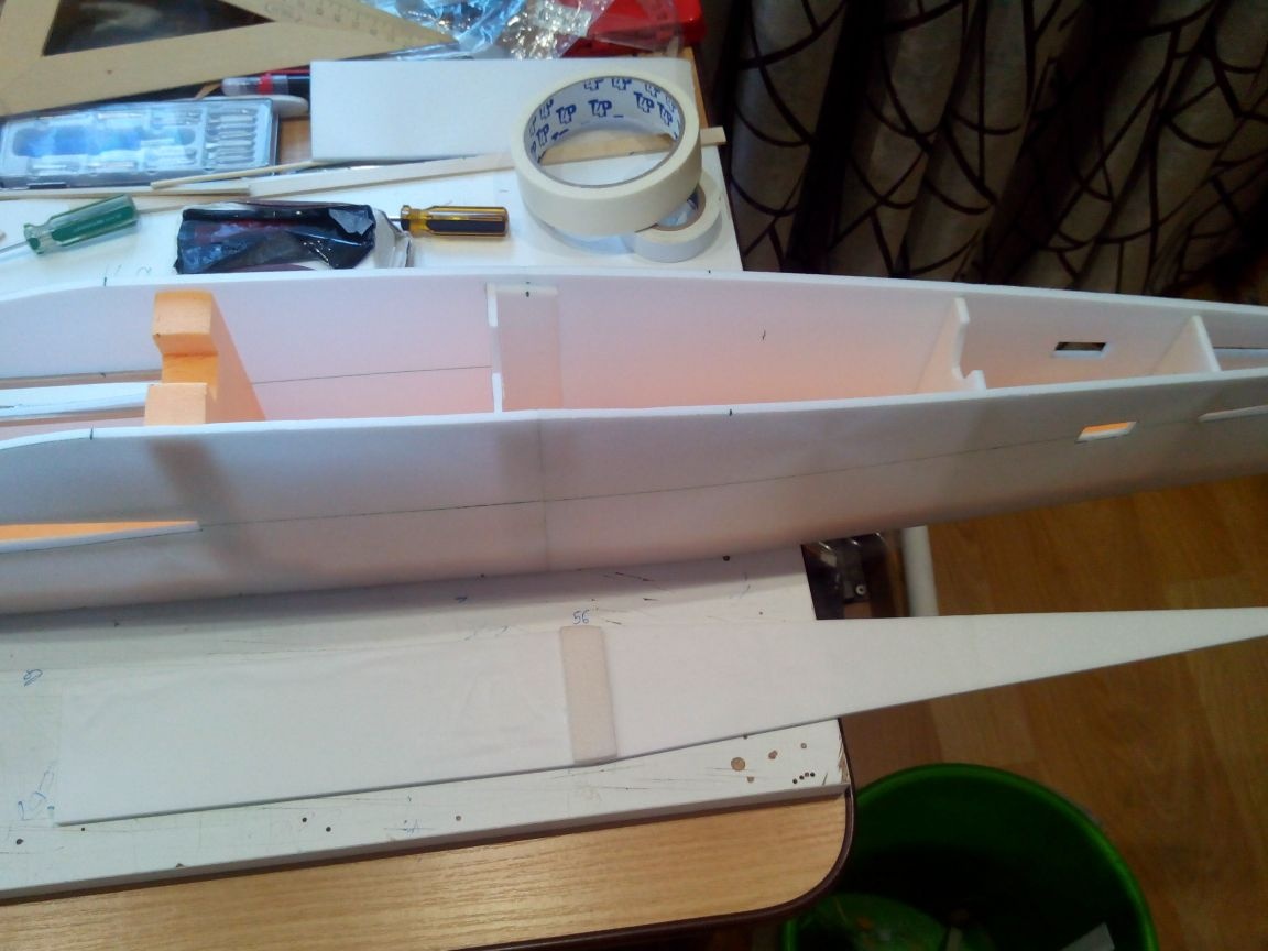
Step 3. Making the fuselage.
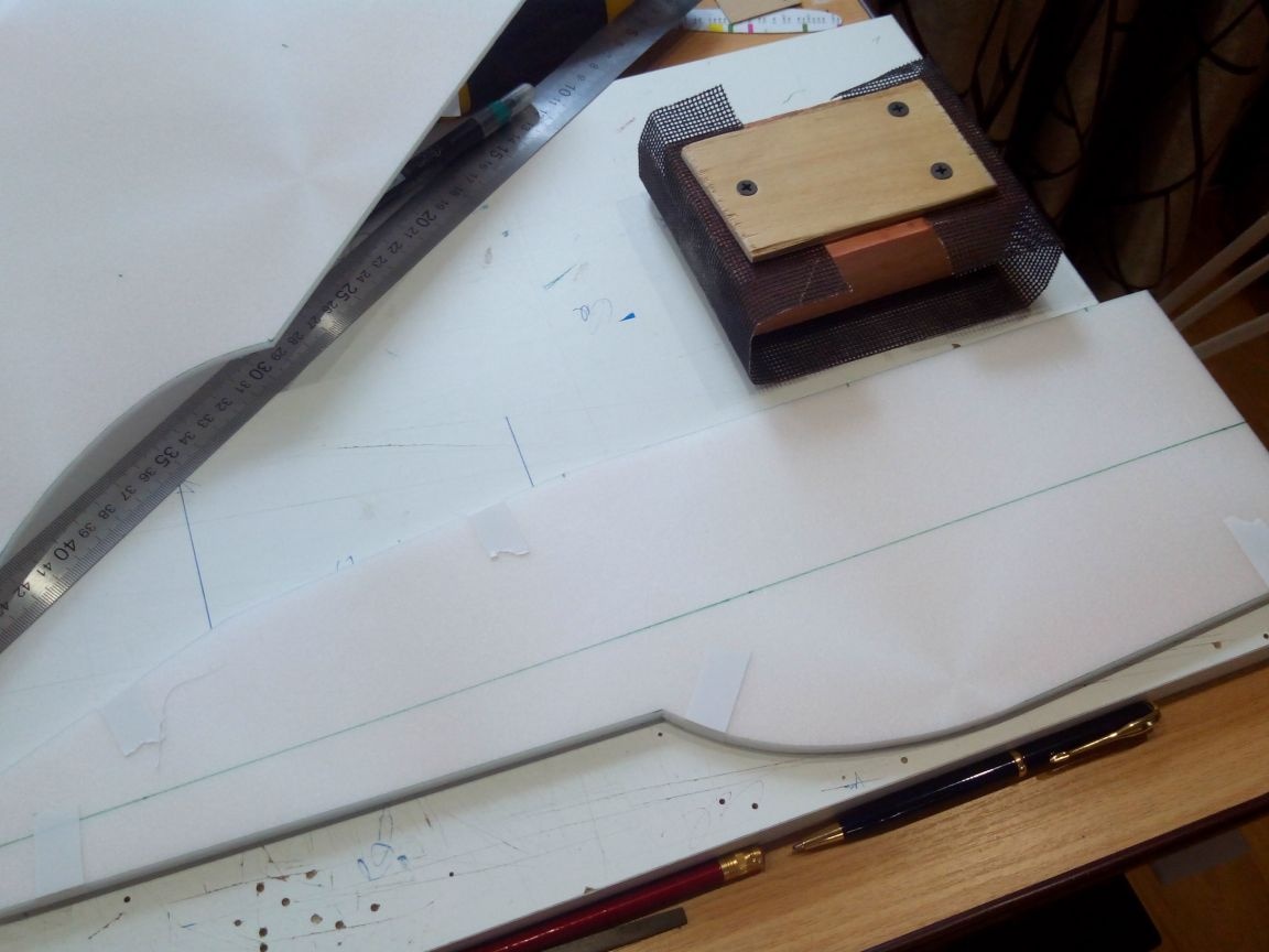
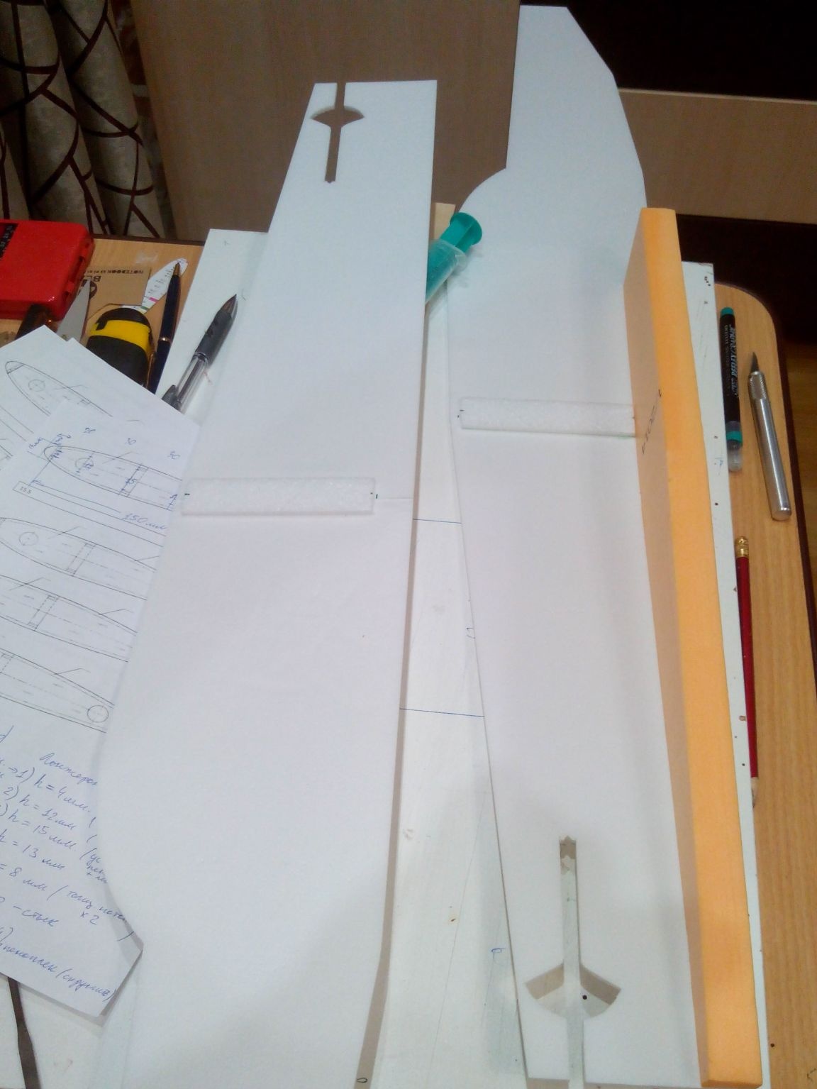
We circle the front part according to the template with a marker on the sheet of the ceiling directly on the front side and draw the axis on which the motor, wing and stabilizer will be located. In addition, this line will be the border separating the colors when pasting the model with tape.
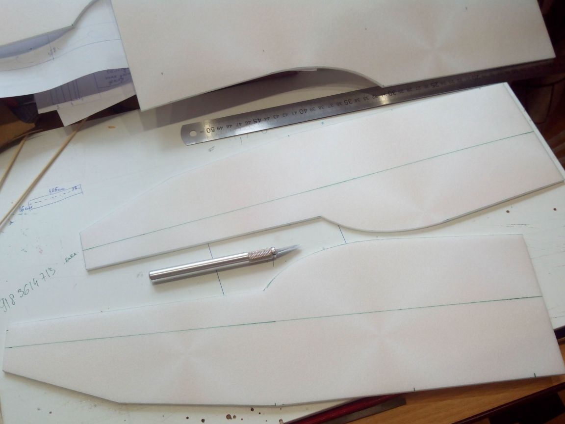
We process parts of the fuselage together with sandpaper, just as the ailerons were processed.
The tail parts are aligned in the same way as the nasal. Immediately, while they are connected in a pack, we cut out the places under the horizontal tail unit and servos. Then trim the file. If you do everything carefully at this stage, then you do not have to align the stabilizer.
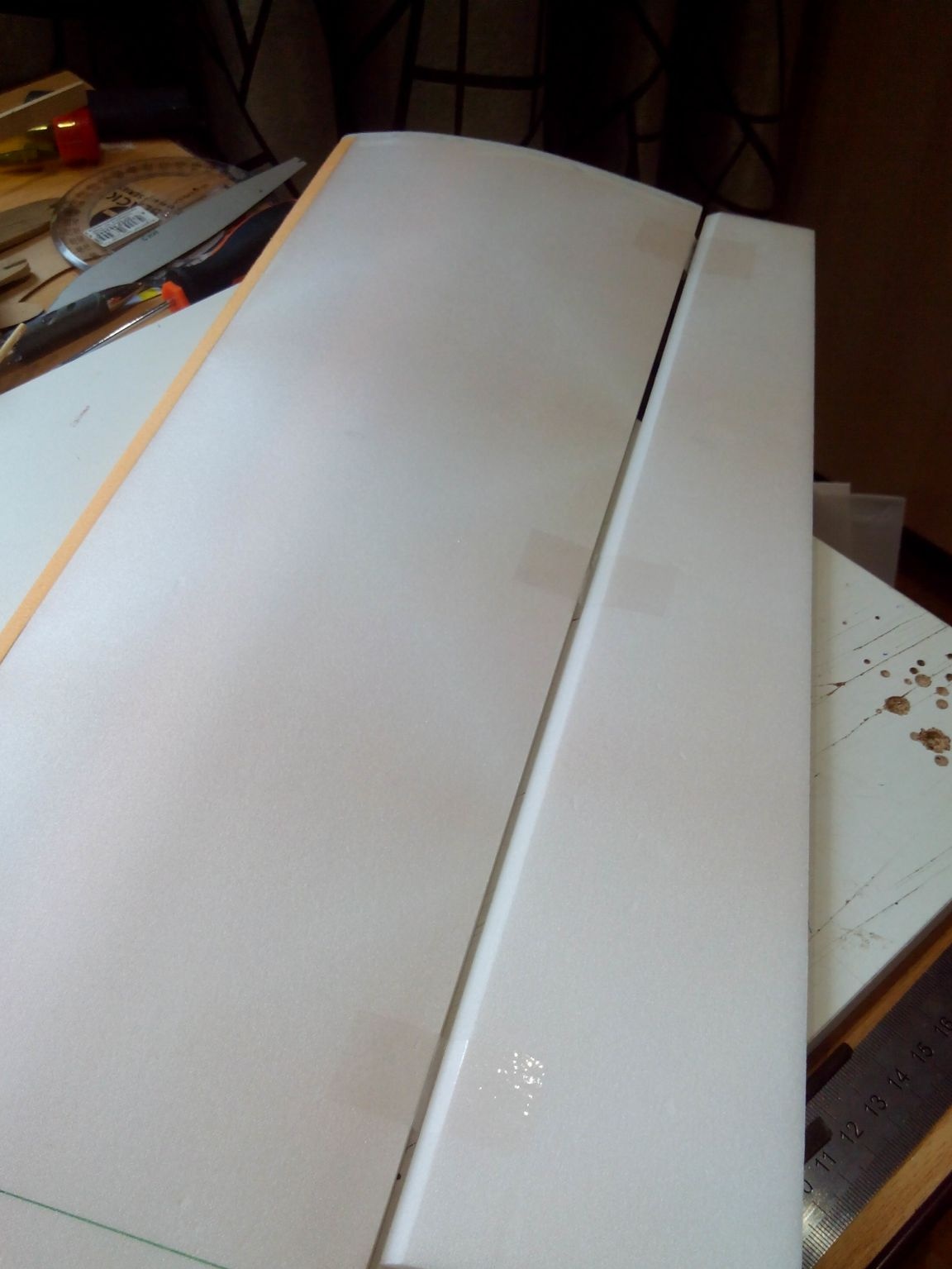
Connecting the parts of the fuselage is better combining along the center line, so there will be no displacement of the holes for the stabilizer. The edges at the junction of the halves can be corrected with sandpaper. From the inside, at the joint of the halves, glue a strip of ceiling tiles.
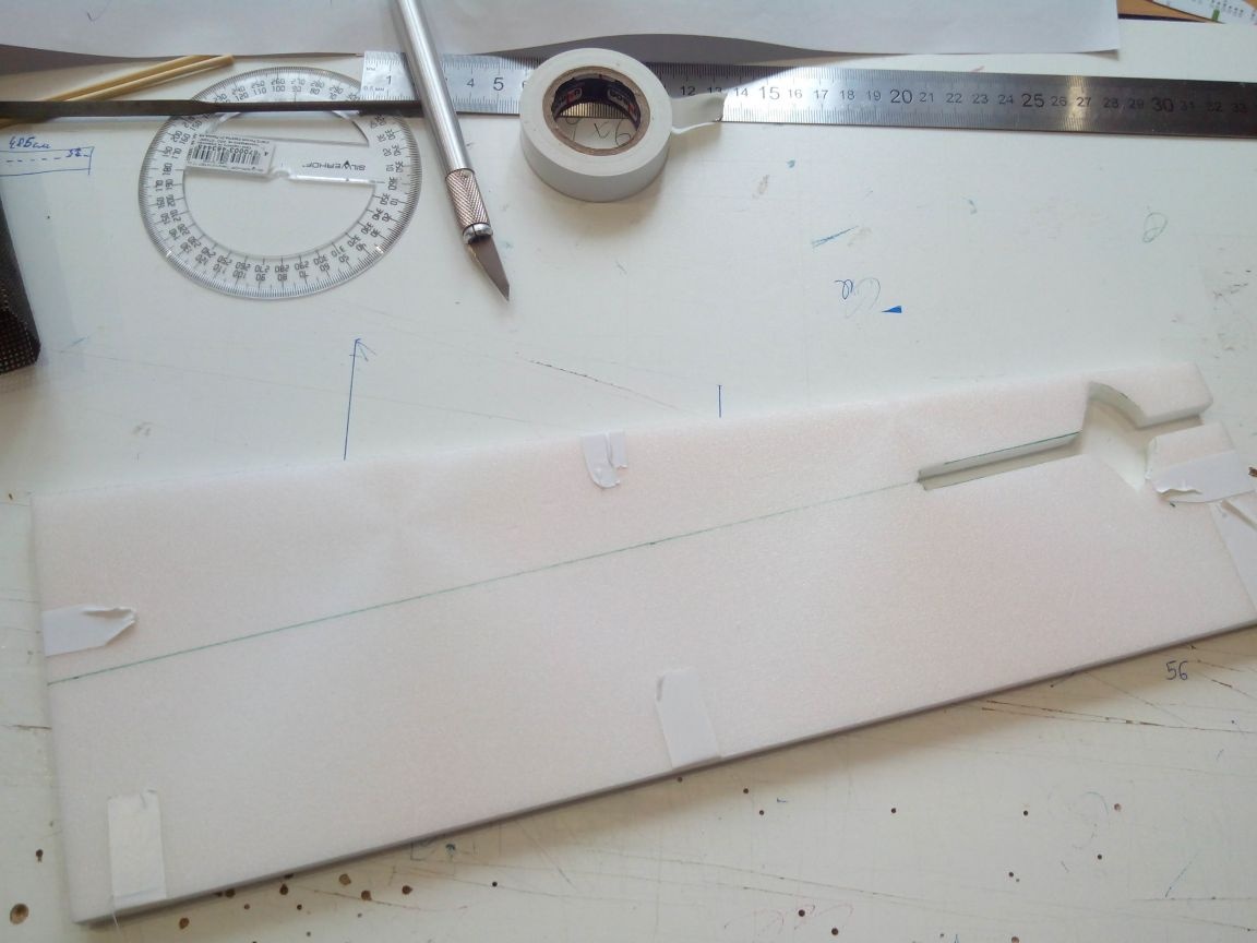
When the glue dries, glue the foam-plastic bottom of the fuselage. At this stage, we align everything according to the square, otherwise the slightest distortion will then affect the flight characteristics. Set aside the fuselage to dry and move on.
Step 4. Production of engine mounts and platforms under the chassis.
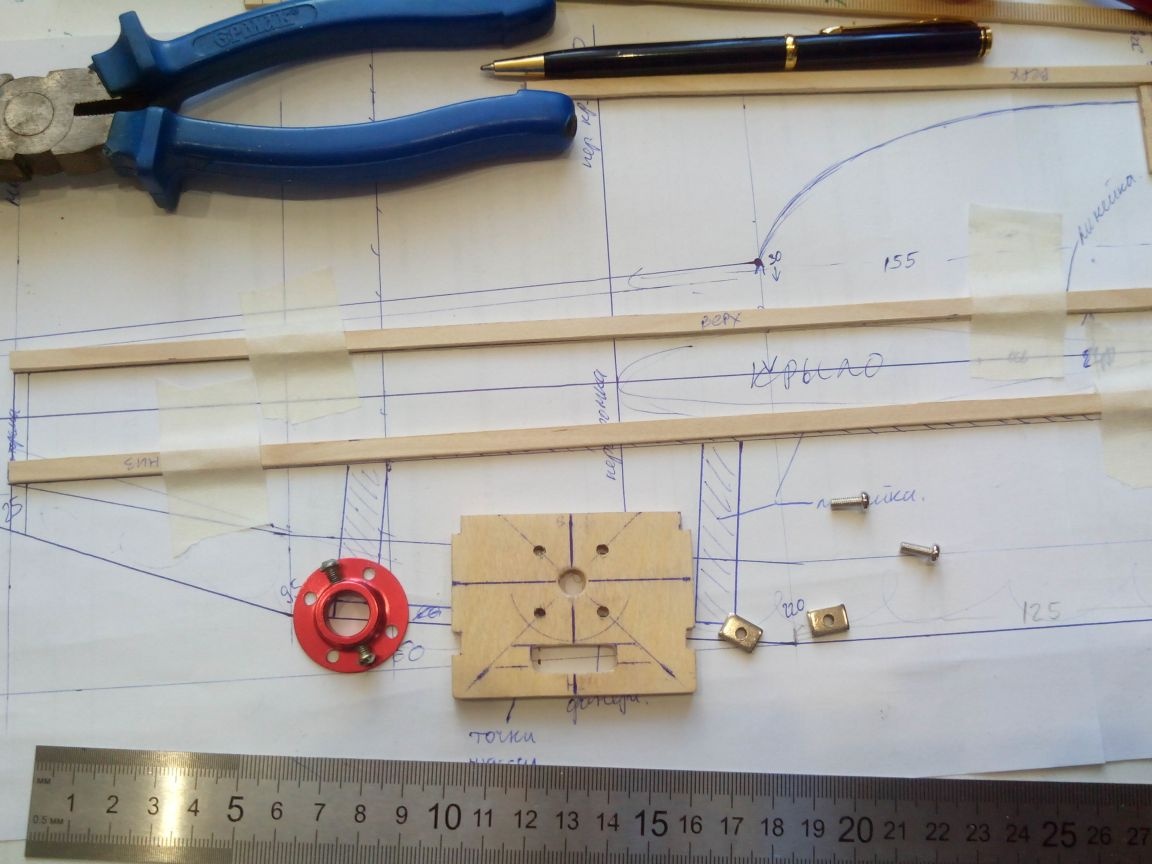
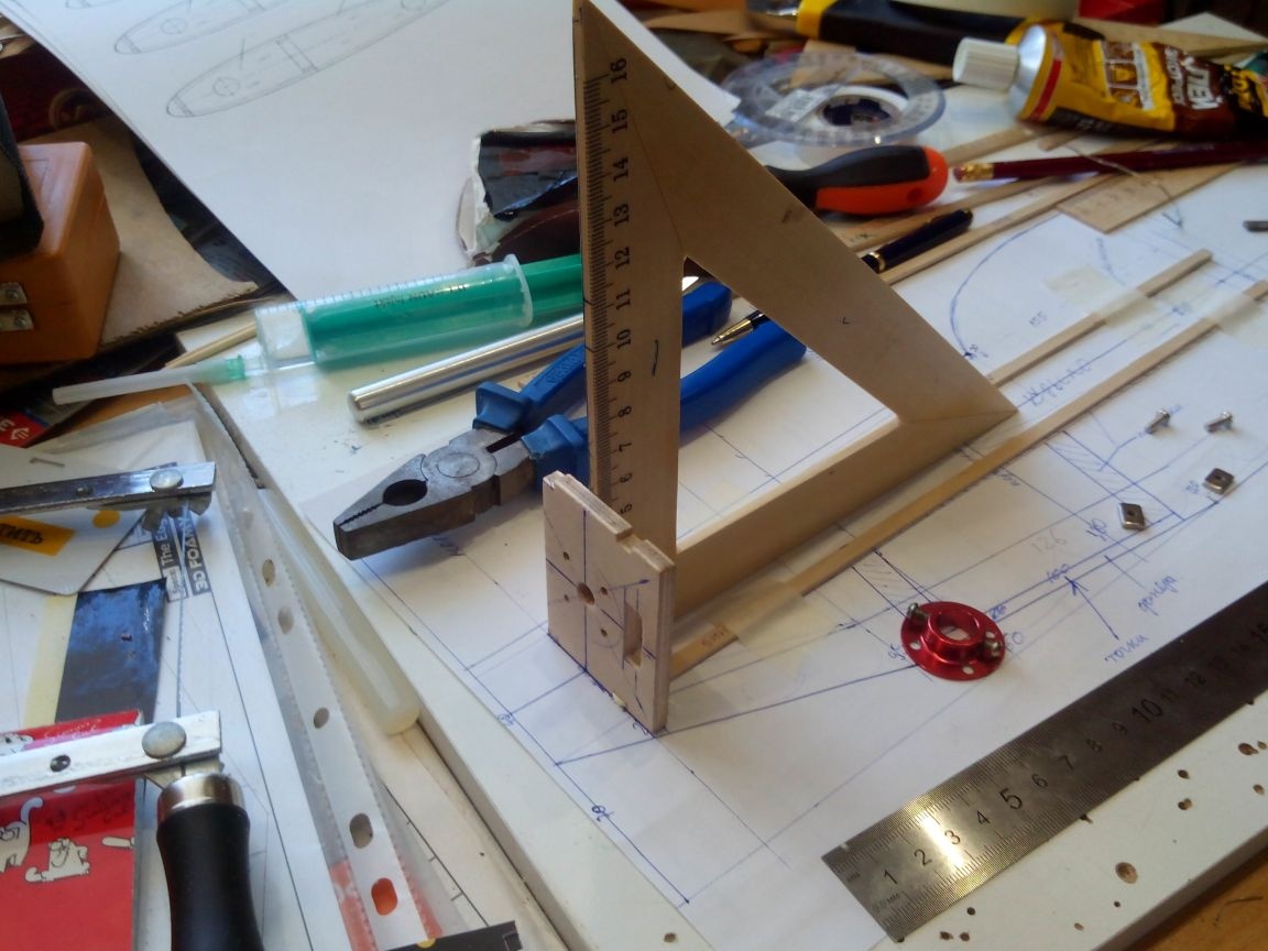
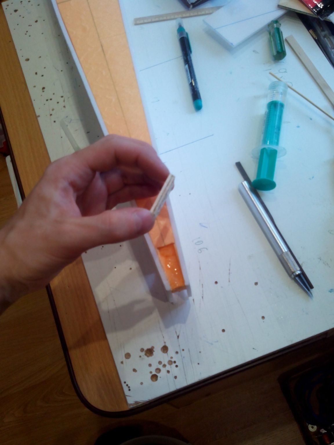
We dissolve the wooden ruler on the slats 5 mm wide and in the drawing we begin to glue the PVA frame with glue. The motor frame is made of 3mm plywood, the hole on it is for outputting wires to the speed controller. Glue all parts using a square. Mowing the engine in the future, if necessary, it is better to implement by placing washers under the motor mount than to gently attach the engine mount.
Then we put racks for the platform under the chassis on the adhesive.
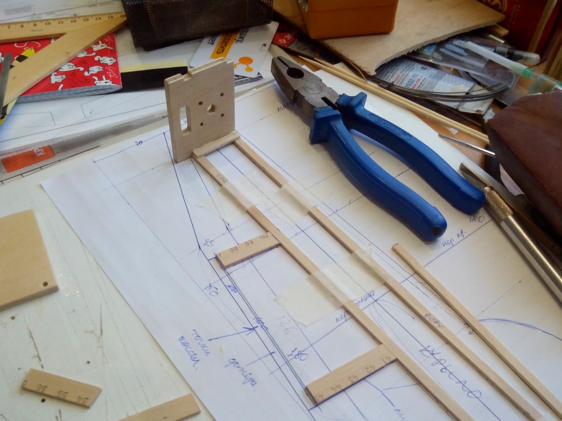
We also cut the platform out of 3 mm plywood. To reduce weight, we drill holes, but you don’t have to be zealous, because during landing this place will receive heavy loads.
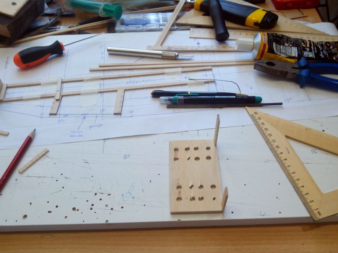
The second part of the structure is glued together in a mirror form and glued to the engine mount and the landing gear. Before the glue dries, we put a plastic card under the right side as a backup.
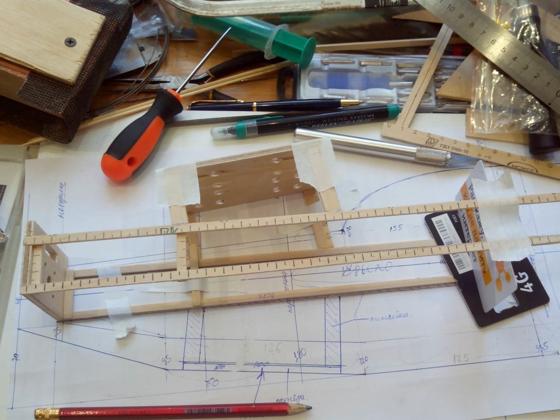
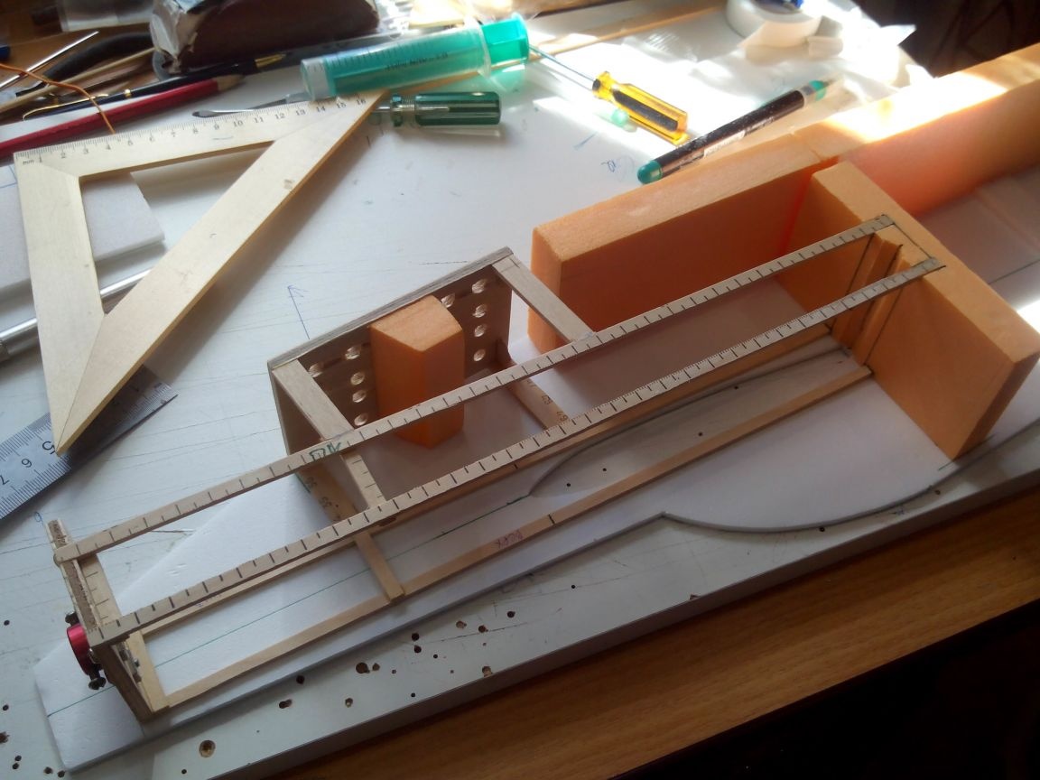
We apply this design to the nose of the fuselage. The wing will be located between two racks.
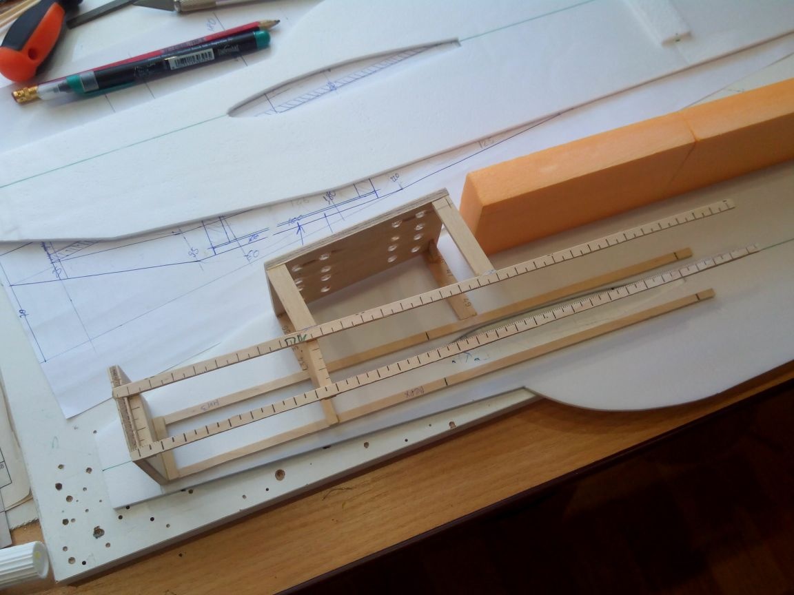
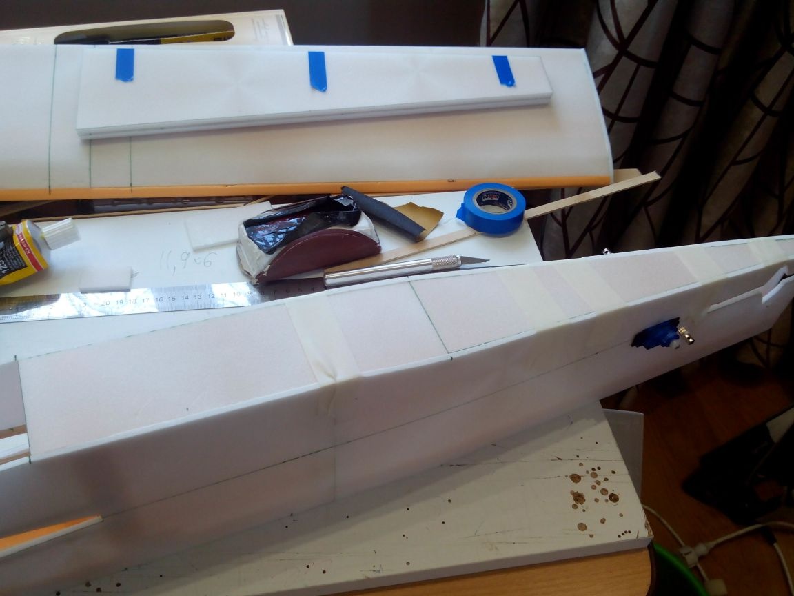
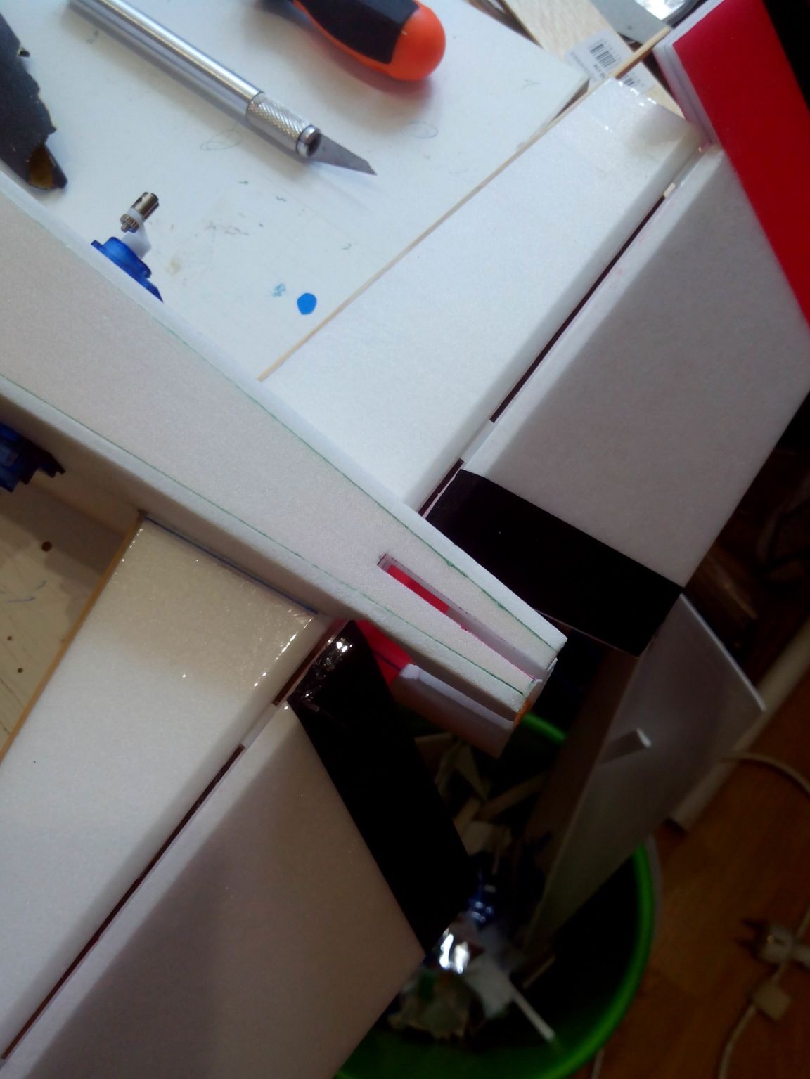
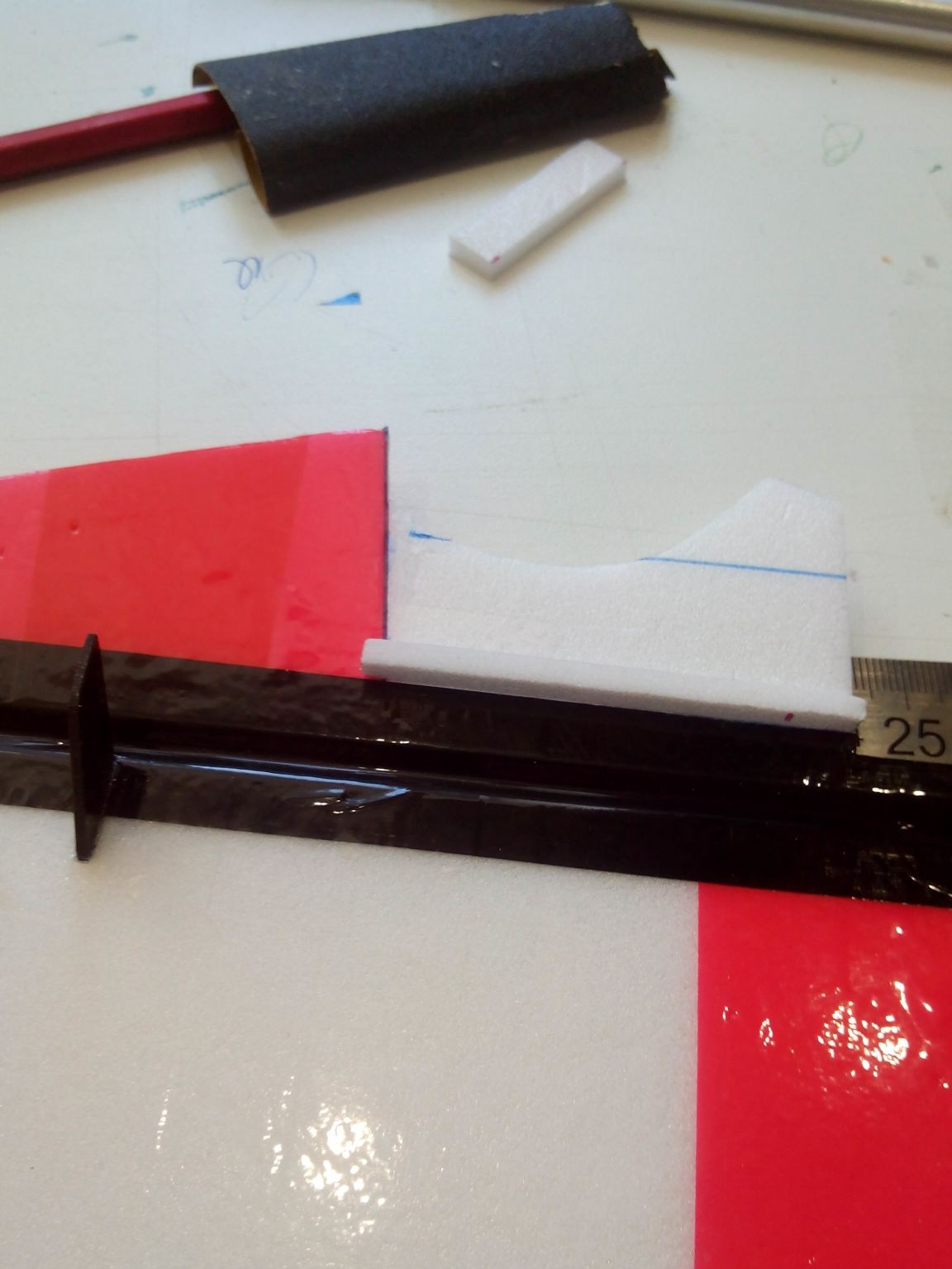
Cut from the foam (20 mm thick) the frame, which will be located immediately behind the wing. We make small recesses under it for slats.
We paste the foam-plastic frame into the fuselage along the square. Then we glue the structure from the engine mount and the platform under the chassis.
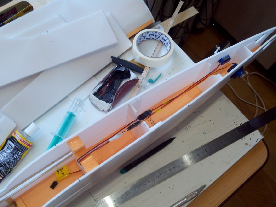
We glue the second part of the fuselage, not forgetting the square. In the tail section we place frames. Places in the frames for wiring tail servos are more convenient to cut in the upper part.
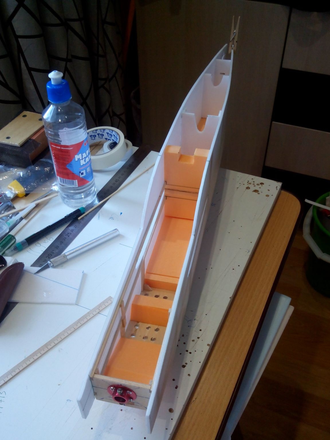
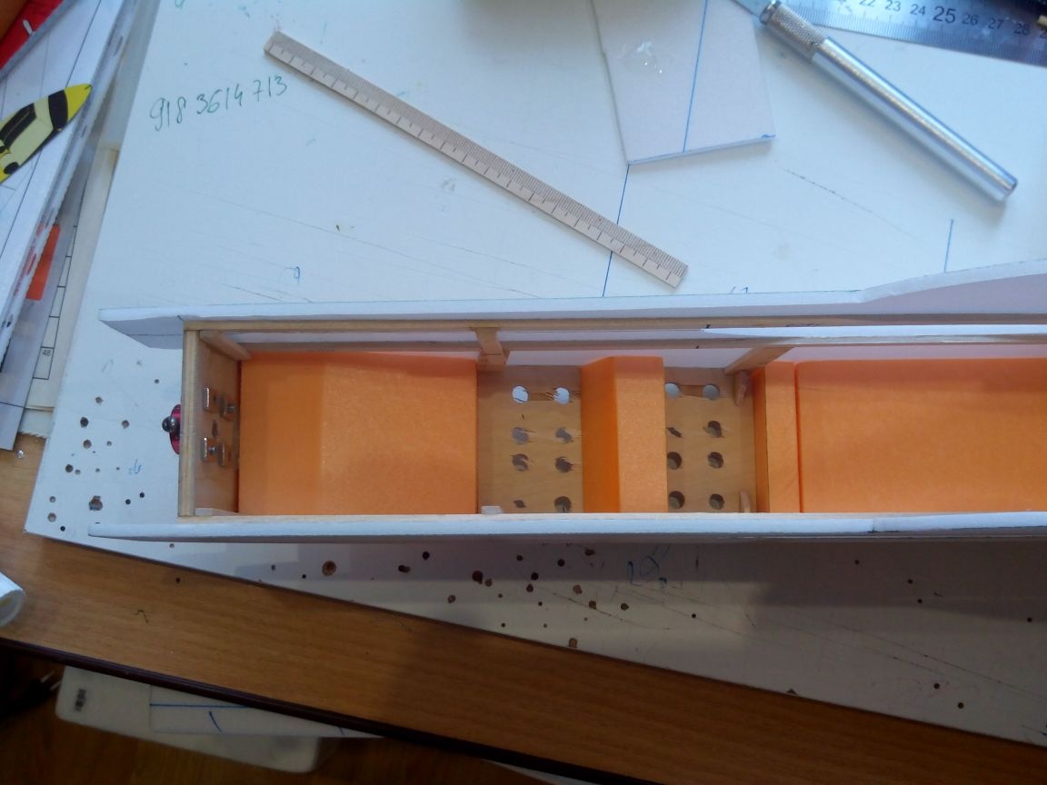
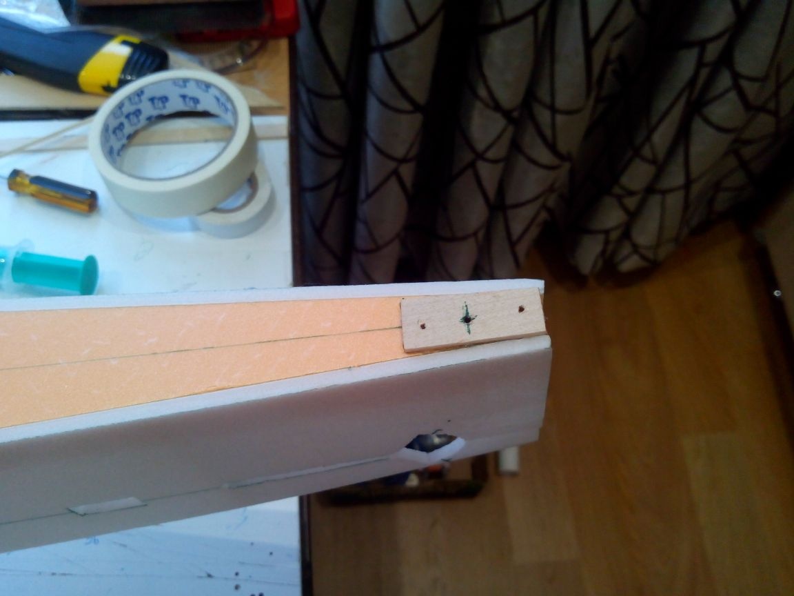
This is what the nose looks like from the inside. We attach a foam block to the chassis mounting pad, then the screws that will be used to fasten the chassis will not damage the electronics.
We prepare the cover for the rear of the fuselage, but do not glue it to make it more convenient to lay the wires in the rear.
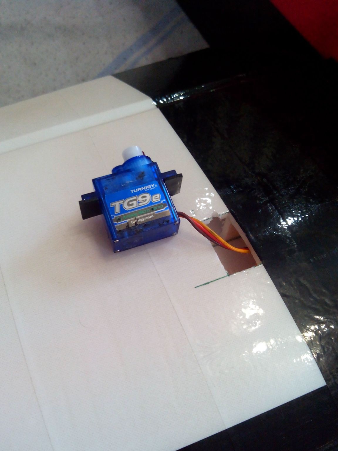
We place the wires of the tail servos, grab them with pieces of adhesive tape, and insert the servos themselves into the holes (without glue). Left - elevator servo, right - rudder. I recommend making appropriate notes on the wires so that later it is easier to connect them to the receiver.
The work inside the tail is finished, you can seal the lid.
We glue the area under the rear wheel from the rulers or take a piece of plywood 3 mm. It is better to glue on five-minute epoxy glue.
In the upper part, strictly in the center, we cut out the seat under the keel.
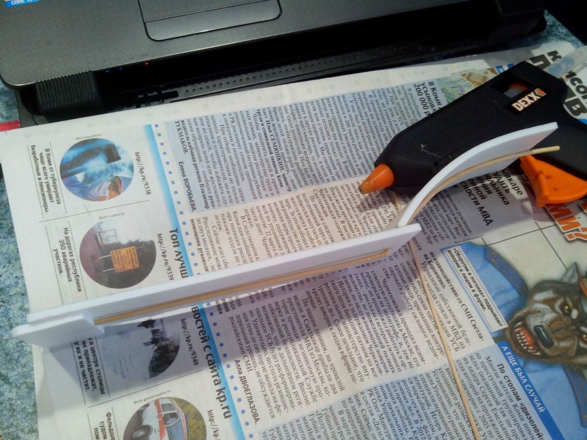
The electronics compartment cover is made from the ceiling. Inside, along the entire lid, glue the bamboo skewer with glue on the ceiling. In the “pseudoglass” part, we bend the skewer by heating it with an iron. To increase strength, we grab the skewer with hot-melt adhesive.
Step 5. The tail.
The stabilizer and keel were left with me from the first model, and then I did not guess to photograph the process. But their manufacture should not cause difficulties.
The stabilizer and elevator are made of two layers of ceilings strictly according to the drawings, and the hinges are made of strips of double-sided tape, which is glued between the layers. The joint, by analogy with ailerons, is sanded from both sides at an angle of 45 degrees. In addition, a wire reinforcement is glued between the layers of the ceiling in the elevator so that both halves work synchronously. Glue bamboo skewers to the front edge of the stabilizer, always with a protrusion beyond. So the stabilizer will be stronger, and the bamboos will protect the gap from getting grass during takeoffs and landings.
The horizontal plumage is ready - you can glue it with tape.
The keel and rudder, for relief, are made of one layer of ceiling tile. The joint is also skinned. The rudder loops are directly covered with tape.
Step 6. Pasting the model with tape.
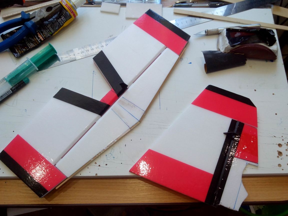
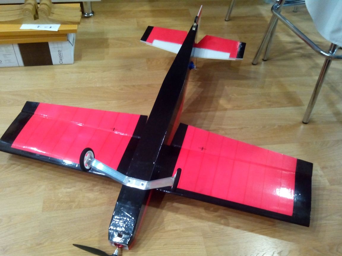
It is better to choose the color of the model from the calculation that it is a transitional model, from a “trainer” to a “pilot”. And therefore it should be well read in the air. Bottom of the fuselage do black, top red. We make the wing from below red, from above white and add black endings. The tail unit is maintained in the same color scheme.
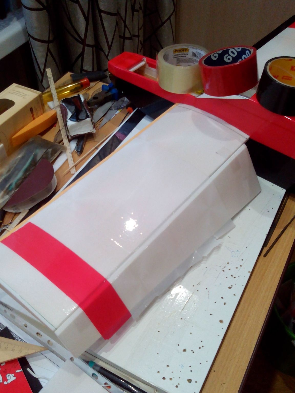
First, glue the fuselage with red tape.
Then we glue the lower part with black tape and glue the tail servos. Best on a five-minute epoxy.
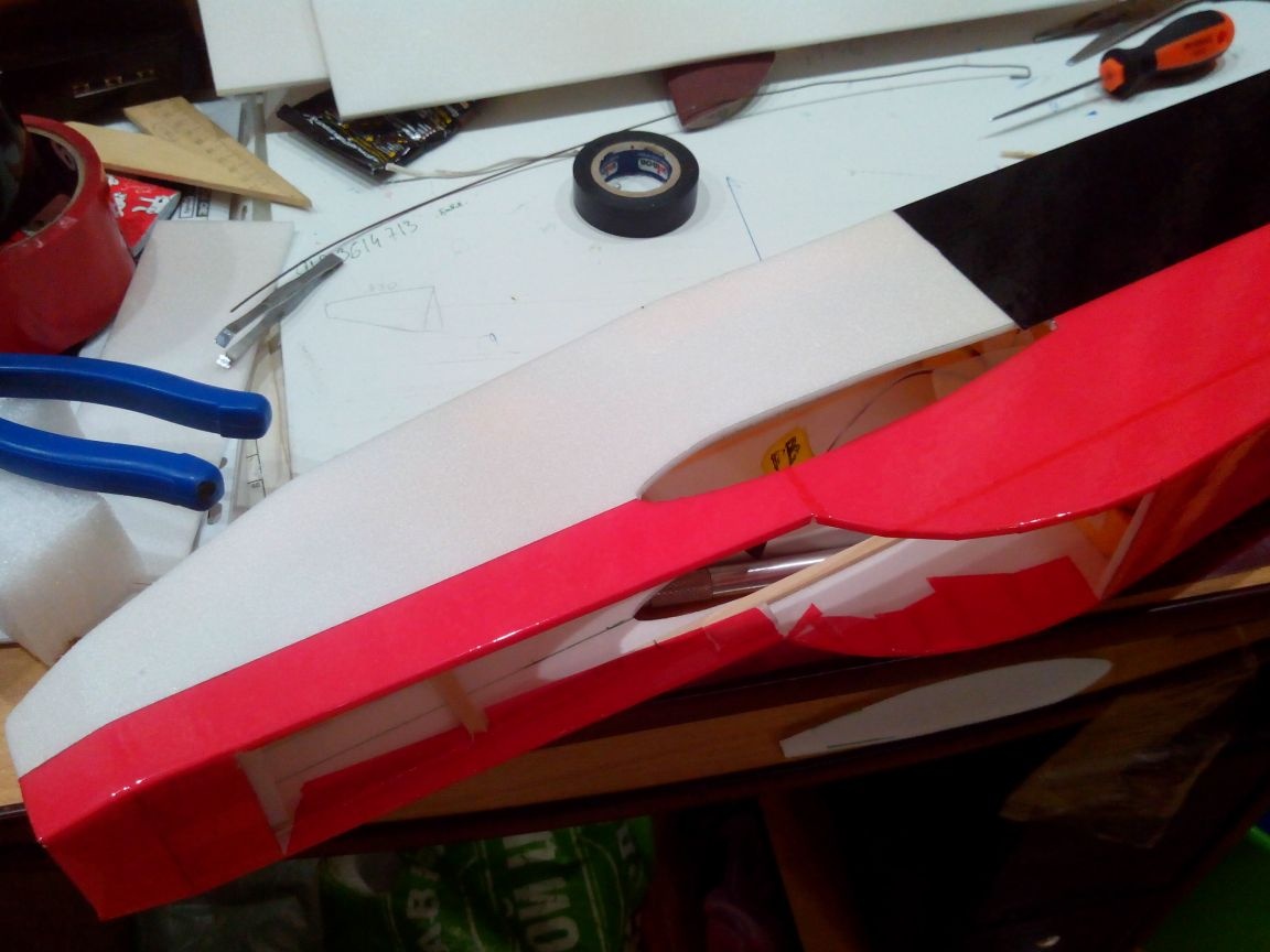
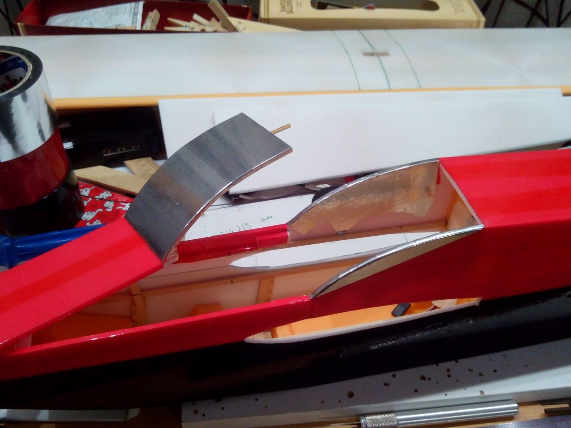
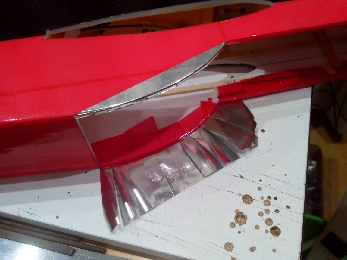
We glue the lid of the compartment with electronics with red tape, and “pseudoglass” with metal tape.
We begin to glue the wing first with white tape, then red, and finish with black so that all inaccuracies are closed.
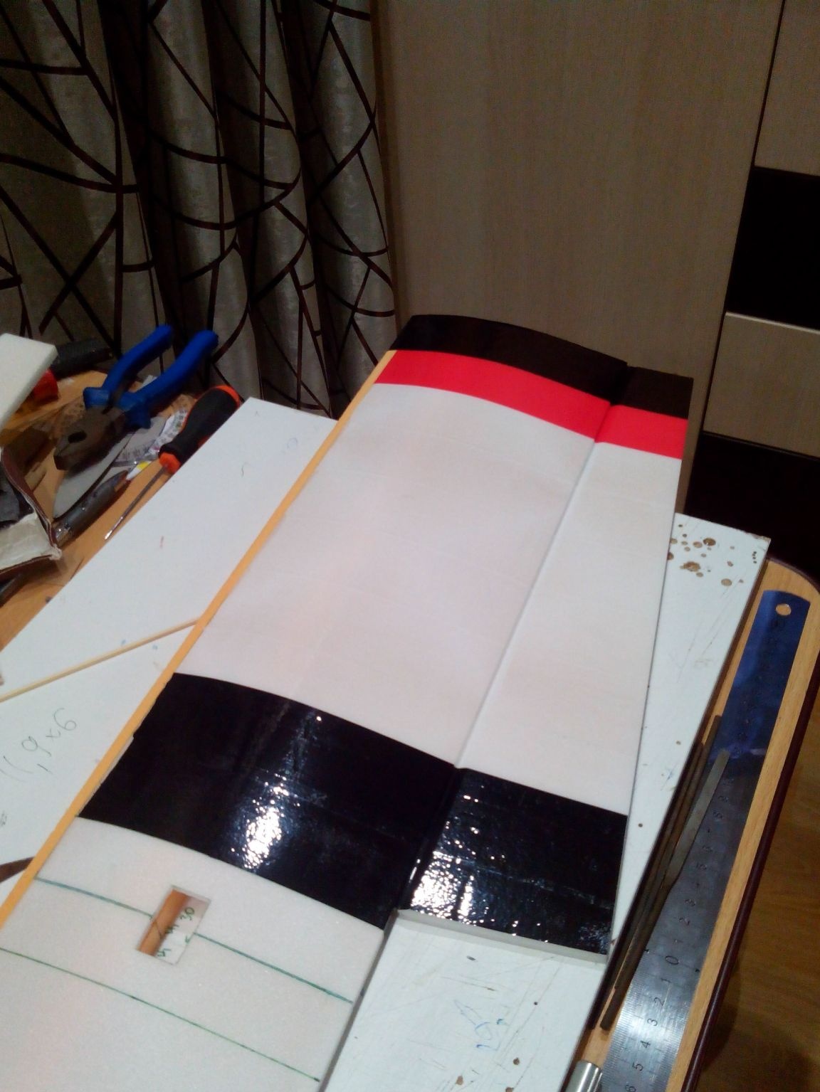
When half of the wing is covered, we insert it into the fuselage, but without glue.
We attach the second aileron and glue the second half symmetrically to the first.
After completing the tightening, glue the wing. For greater strength, it is better to glue on epoxy, but if it is not, use ceiling glue with fixing with hot glue from the inside.
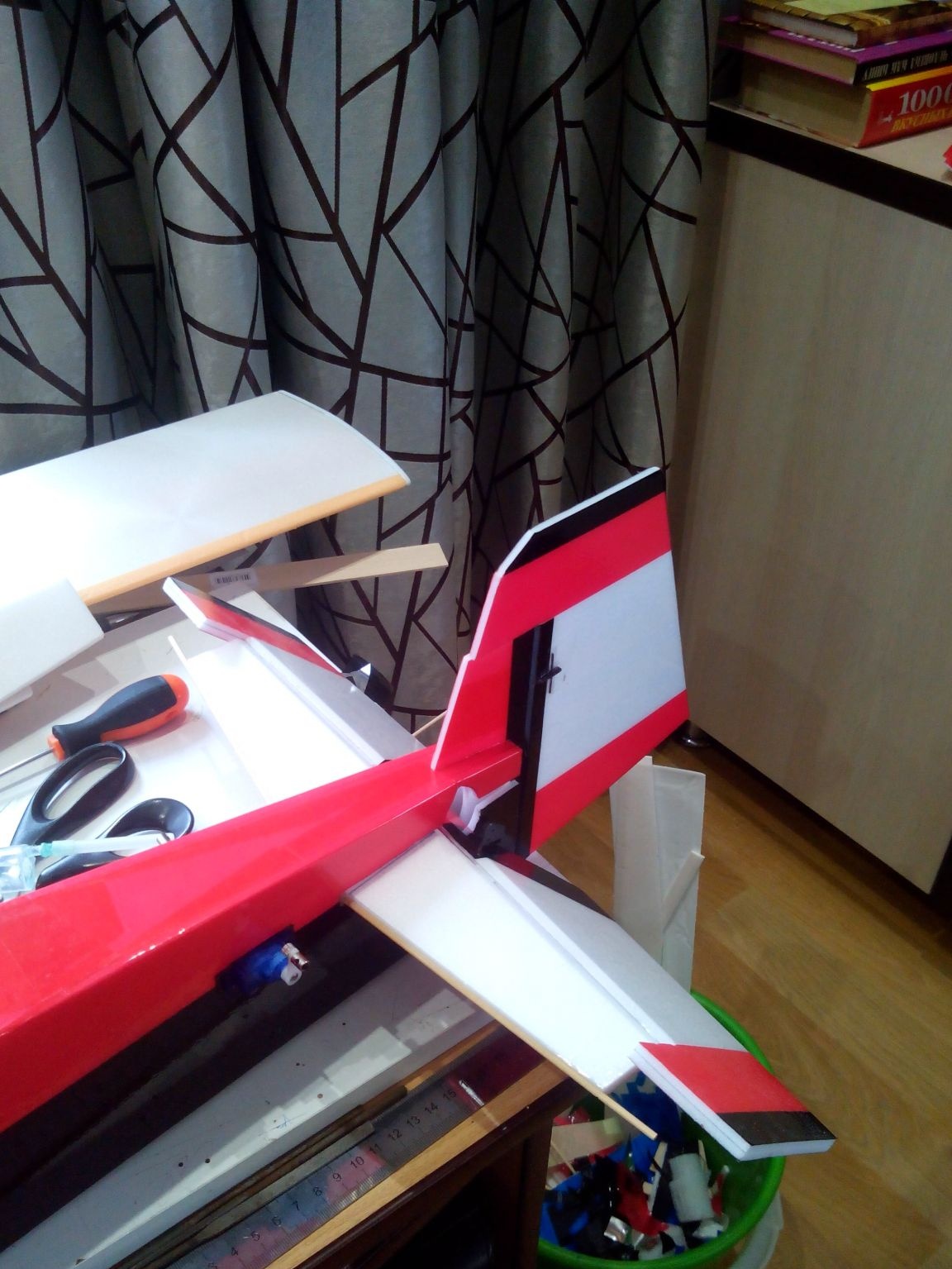
Step 7. Gluing the stabilizer and keel.
It is better to glue the stabilizer by placing the fuselage on a flat surface in order to control horizontality.
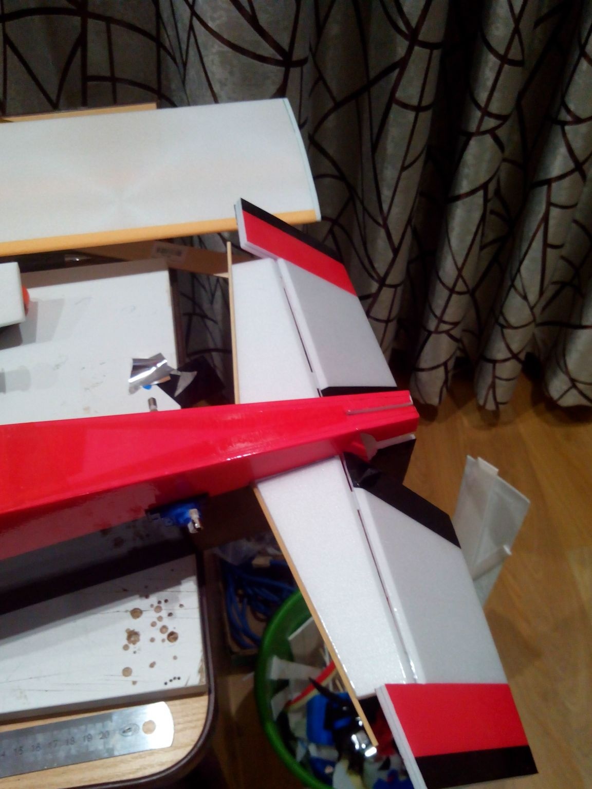
To fix the keel more reliably, we glue two pieces of the ceiling to it, and so that the elevator does not touch it, we make a cutout. The vertical installation of the keel can be checked with a plumb or a large square.
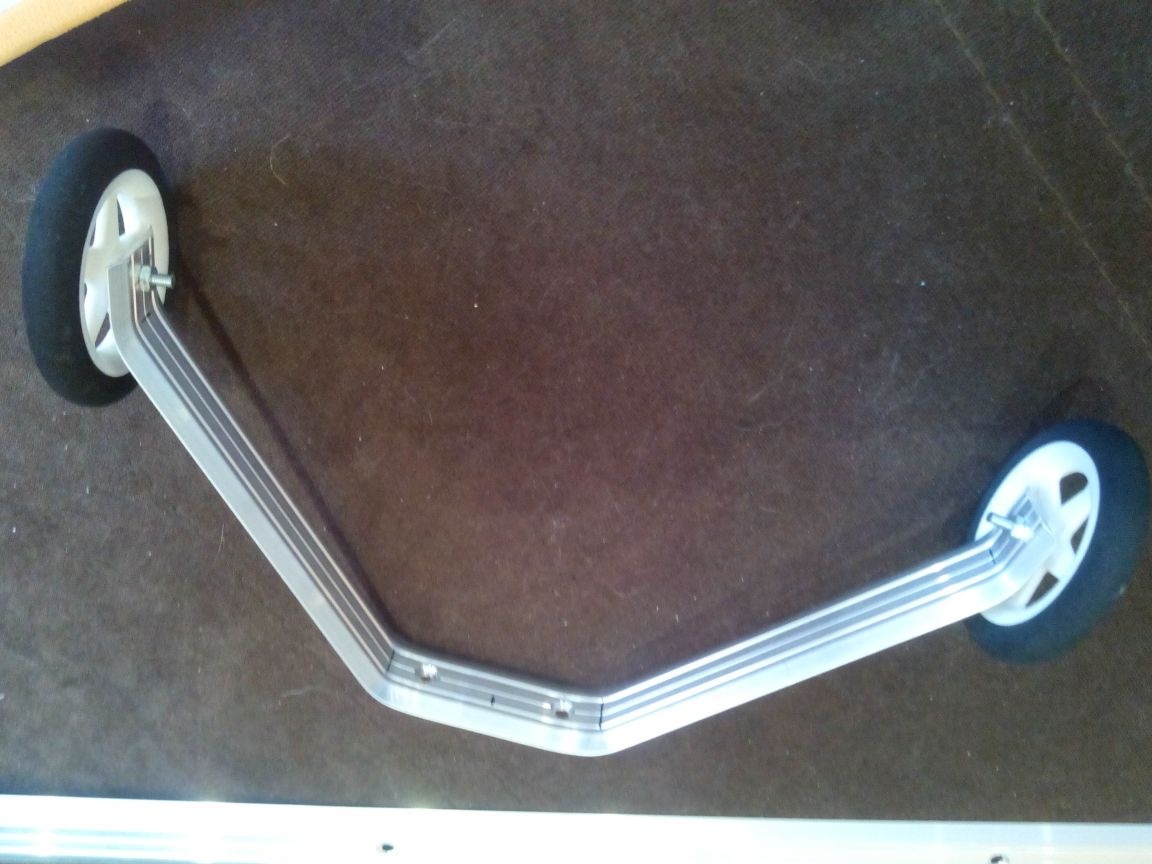
Step 8. Making the chassis.
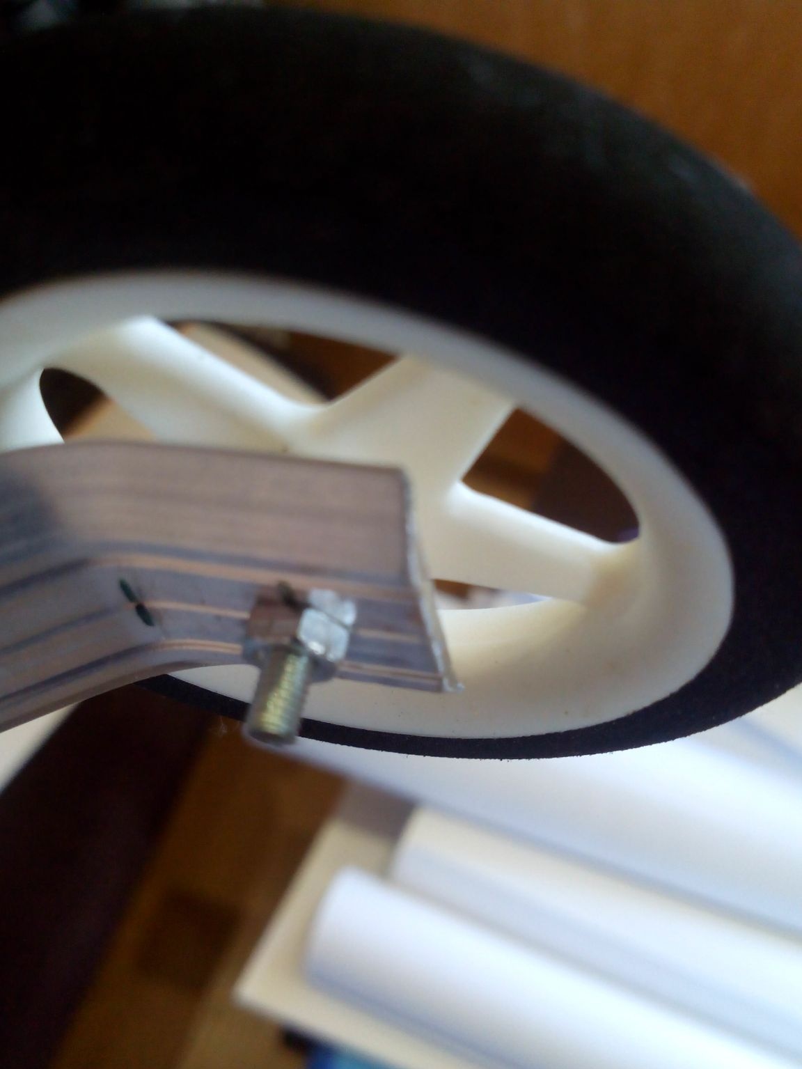
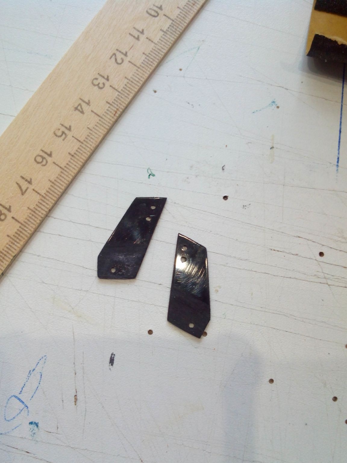
We bend the landing gear from the plate to close the joints in linoleum. At the ends we drill holes for axle bolts.
We drill a hole in the wheel to the desired diameter and fasten it to the rack. It is better to fix the nut with a drop of nail polish or with a special thread lock.
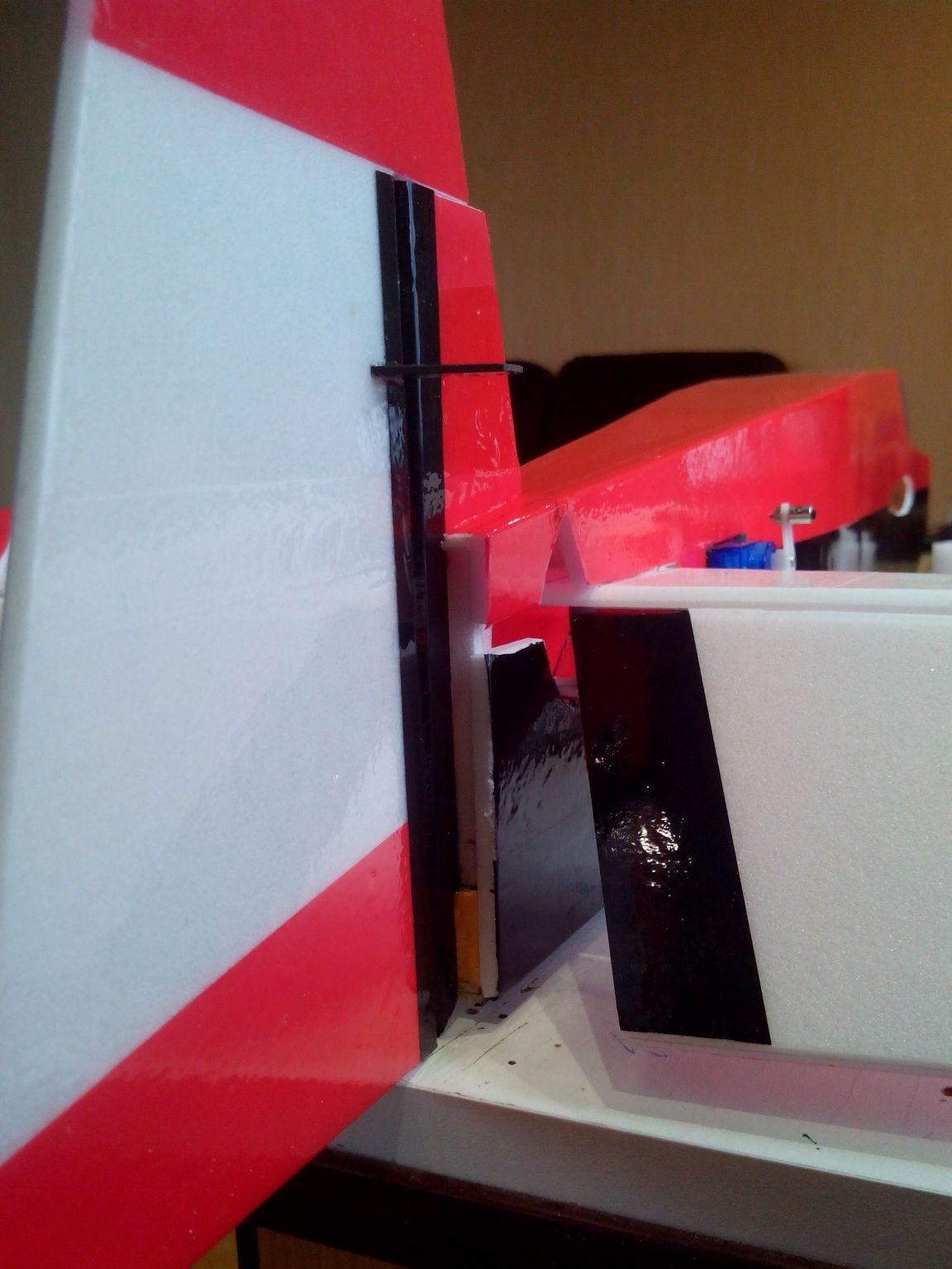
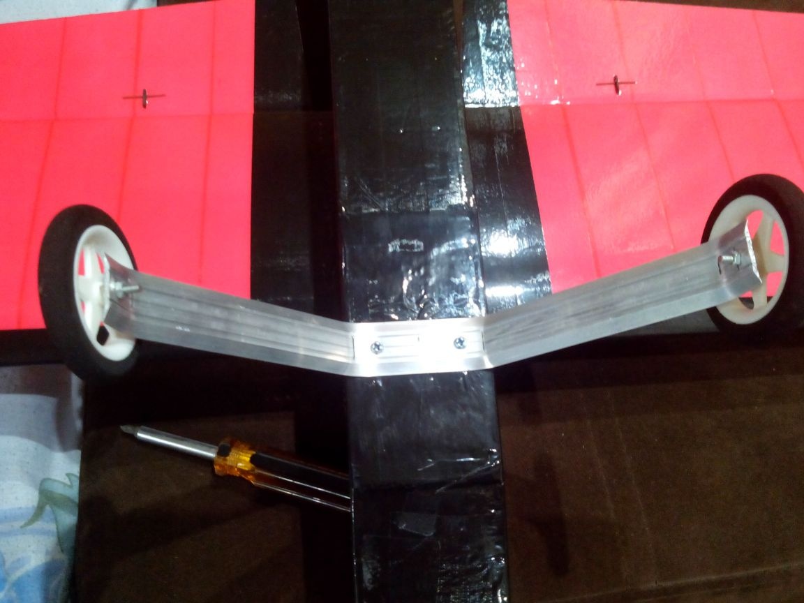
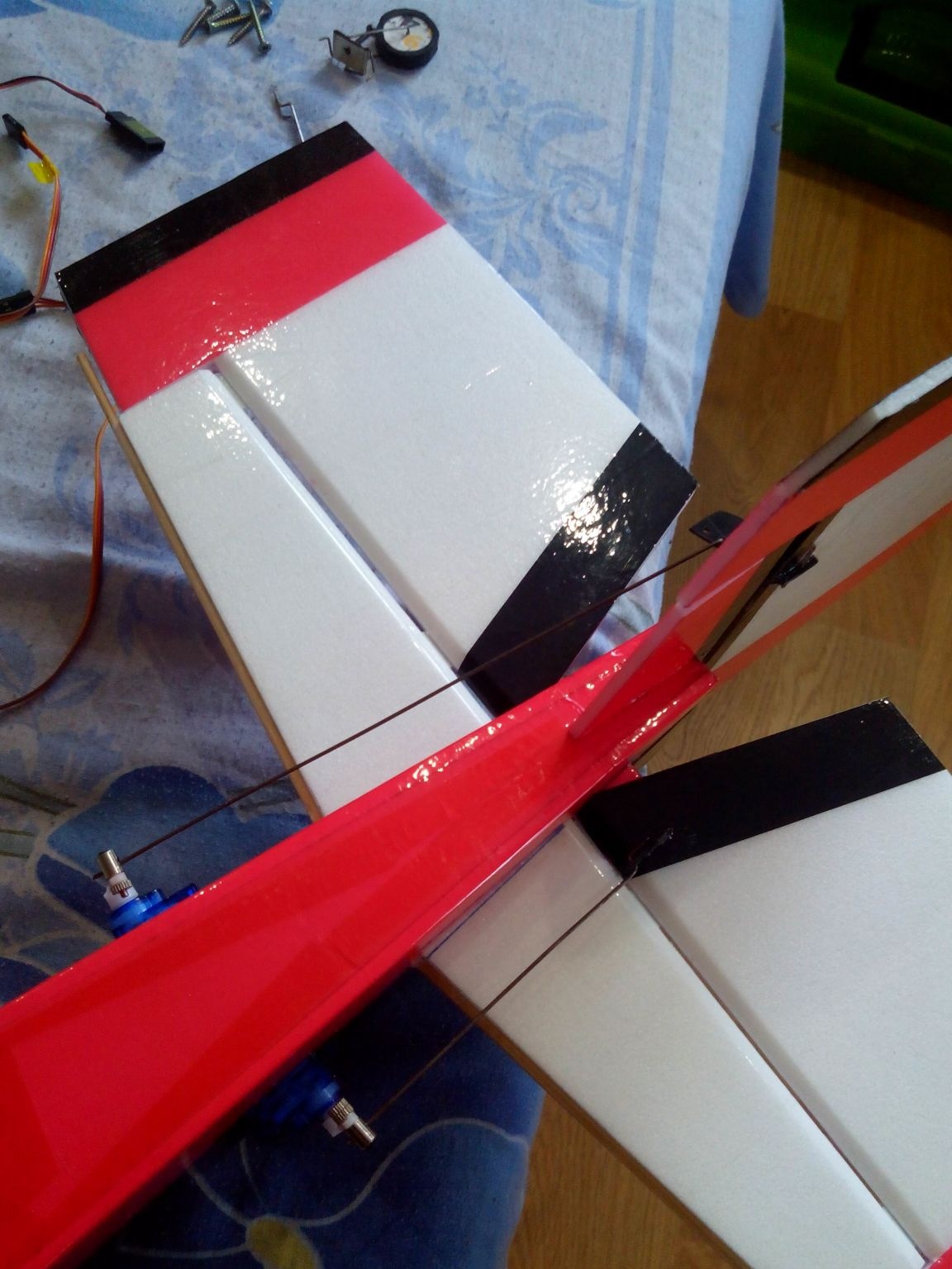
We fasten the landing gear to the fuselage with two screws.
We bend the rear rack from steel wire. We fasten everything with a piece of tin to one self-tapping screw.
Step 9. Installing the electronics.
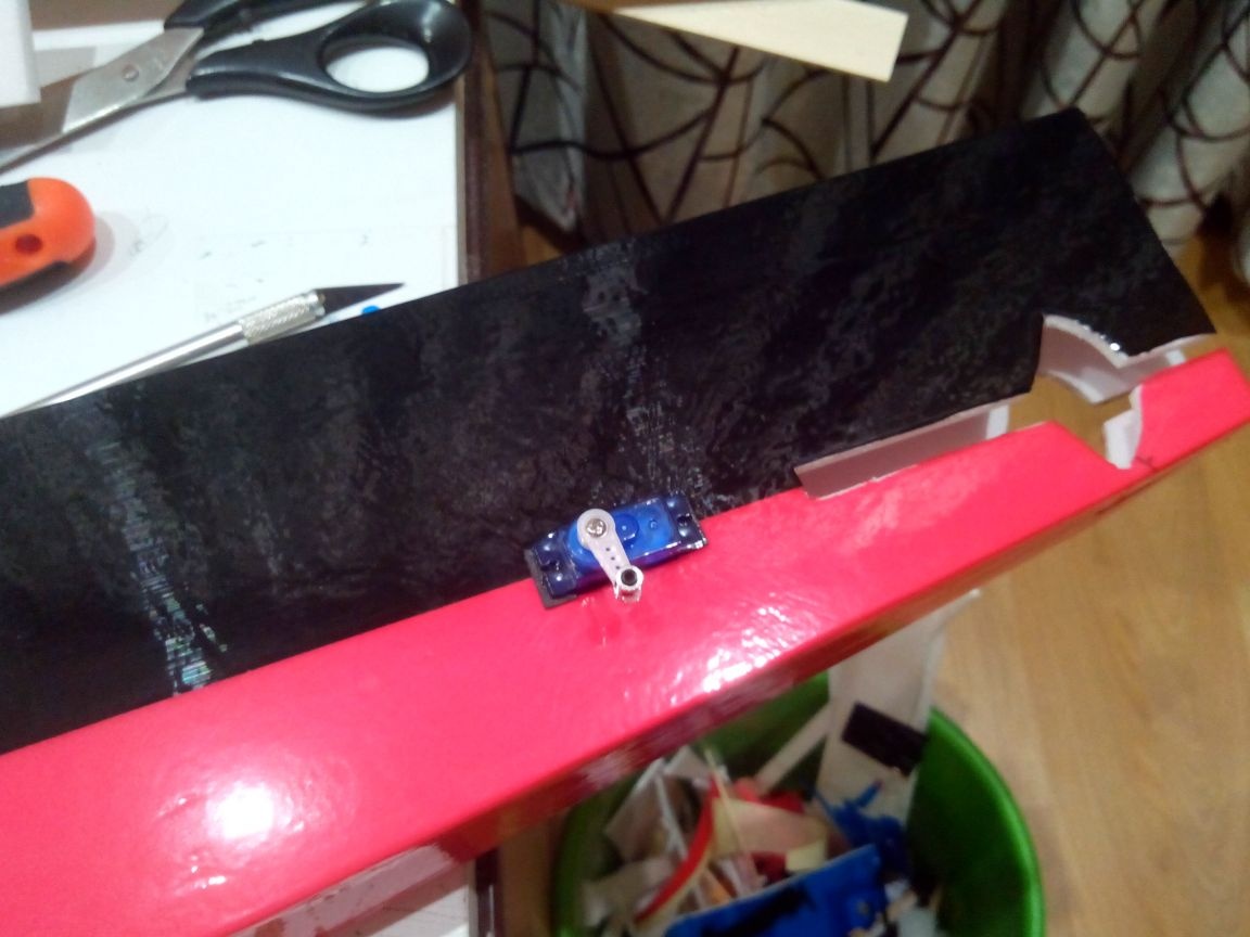
Using a needle, we “find” a wooden spar in the wing, apply the servo with the base, circle the marker and cut out the seat. Using the bent wire, we extend the ends of the Y-cable into the holes.
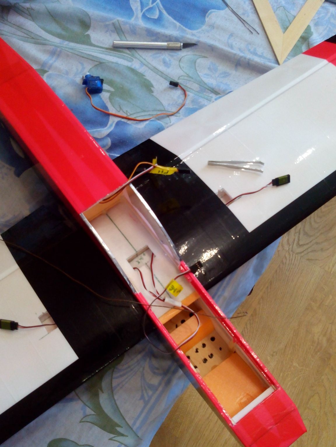
We connect the servos to the Y-cable and fix them in the seats with mounting tape or epoxy glue.
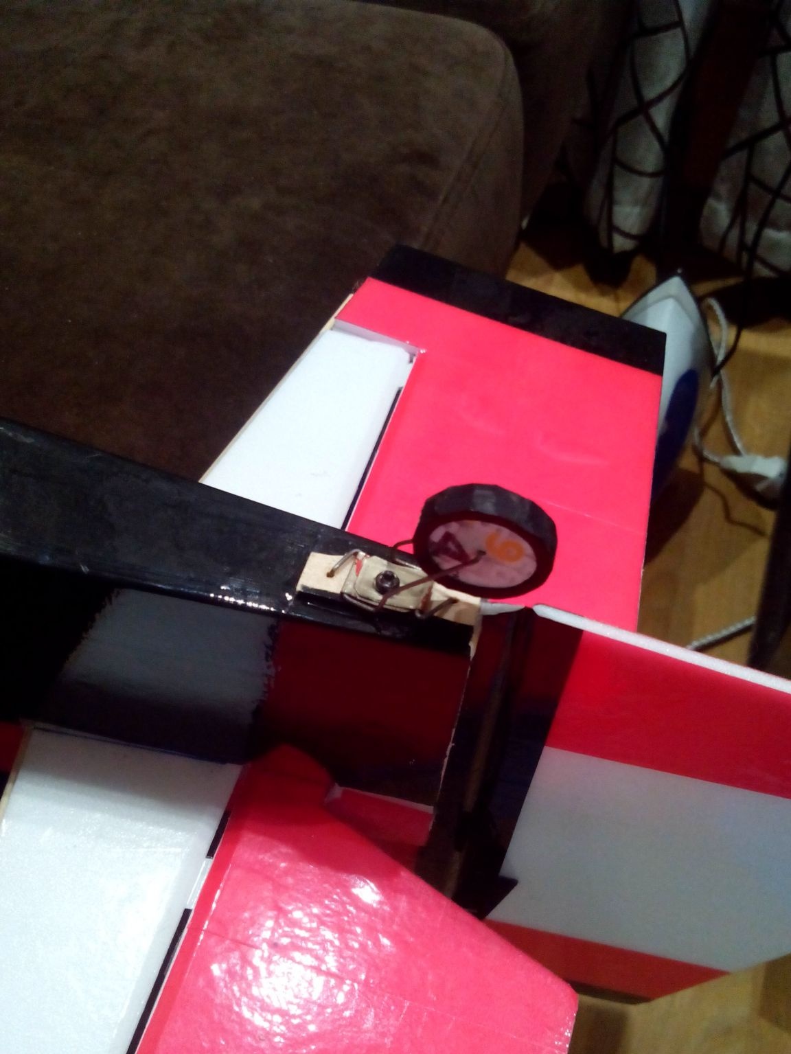
Boars in steering wheels and ailerons can be glued purchased or make them yourself from suitable plastic, for example, a building corner or an old CD-ROM. With a thin drill, we drill several holes in the boars so that you can mechanically change the costs, and in the lower part we make a hole for a piece of wire, so the boar is better fixed and will not pop out. We glue wild boars on an epoxy five-minute.
The rods are made of rigid steel wire. You can fix it either with latches on both sides, or bend the “snake” on one side, and fix the other end with a latch (as in the photo).
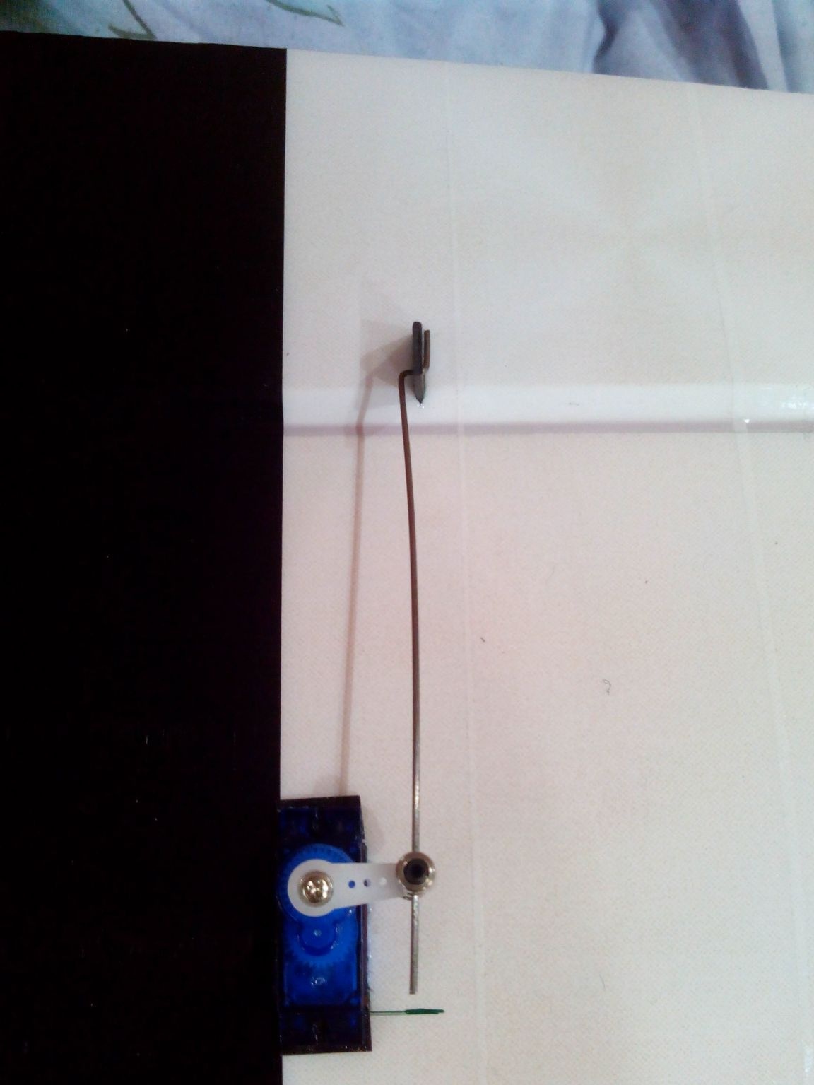
On the tail empennage of the traction and the hog we set in the same way.
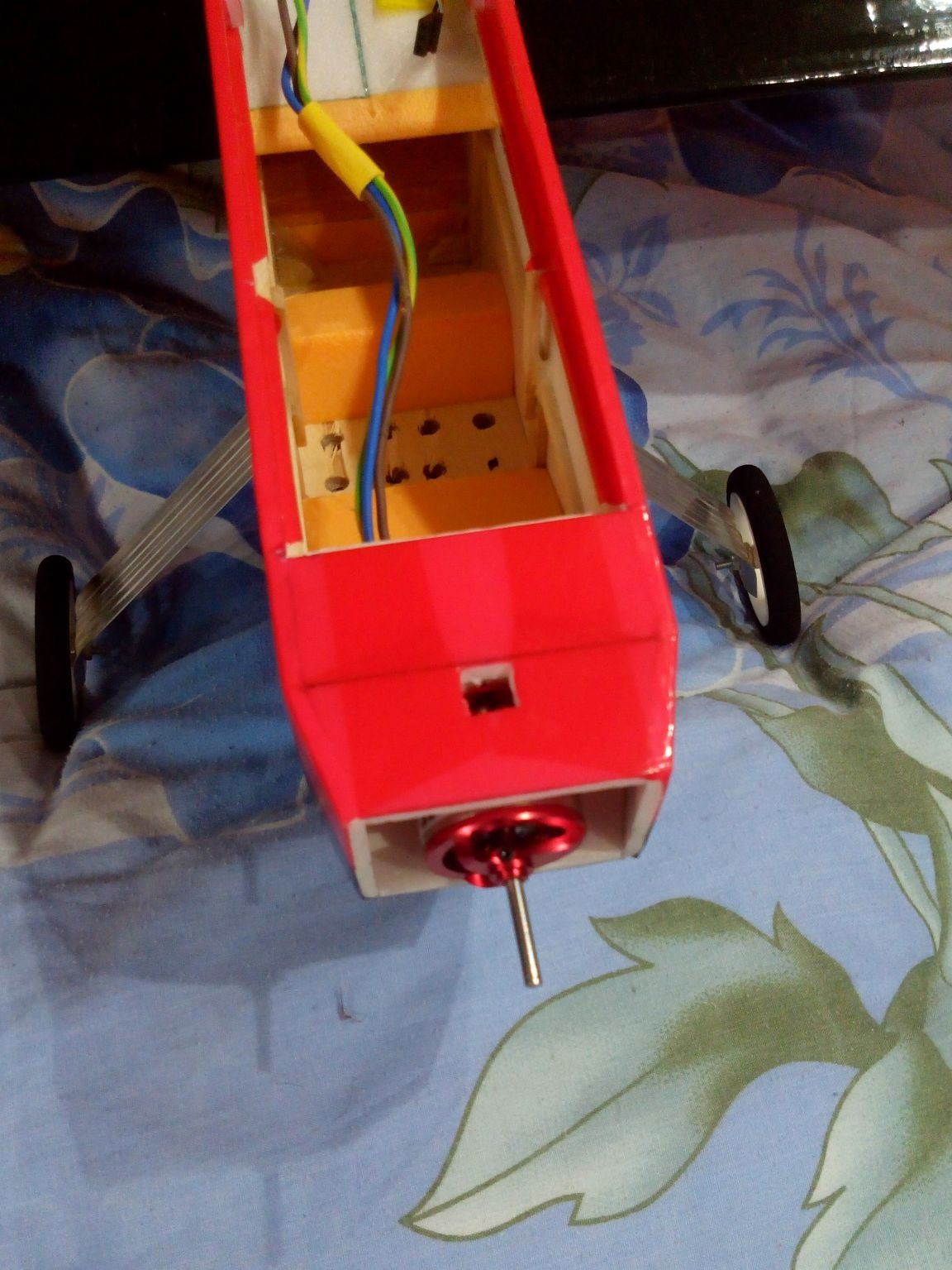
The base of the engine (in this case it is of the "fungus" type) is bolted to the engine mount. And to fix the motor itself on the base, we cut out two holes in the bow (top and bottom) in order to have access to the mounting bolts. On this type of engine, I strongly recommend immediately replacing the countersunk bolts with ordinary bolts, with a screwdriver! Because the hexagon socket screws cannot be tightened well, and if you use a thread lock, then you just can’t unscrew it.
Step 10. The final touches.
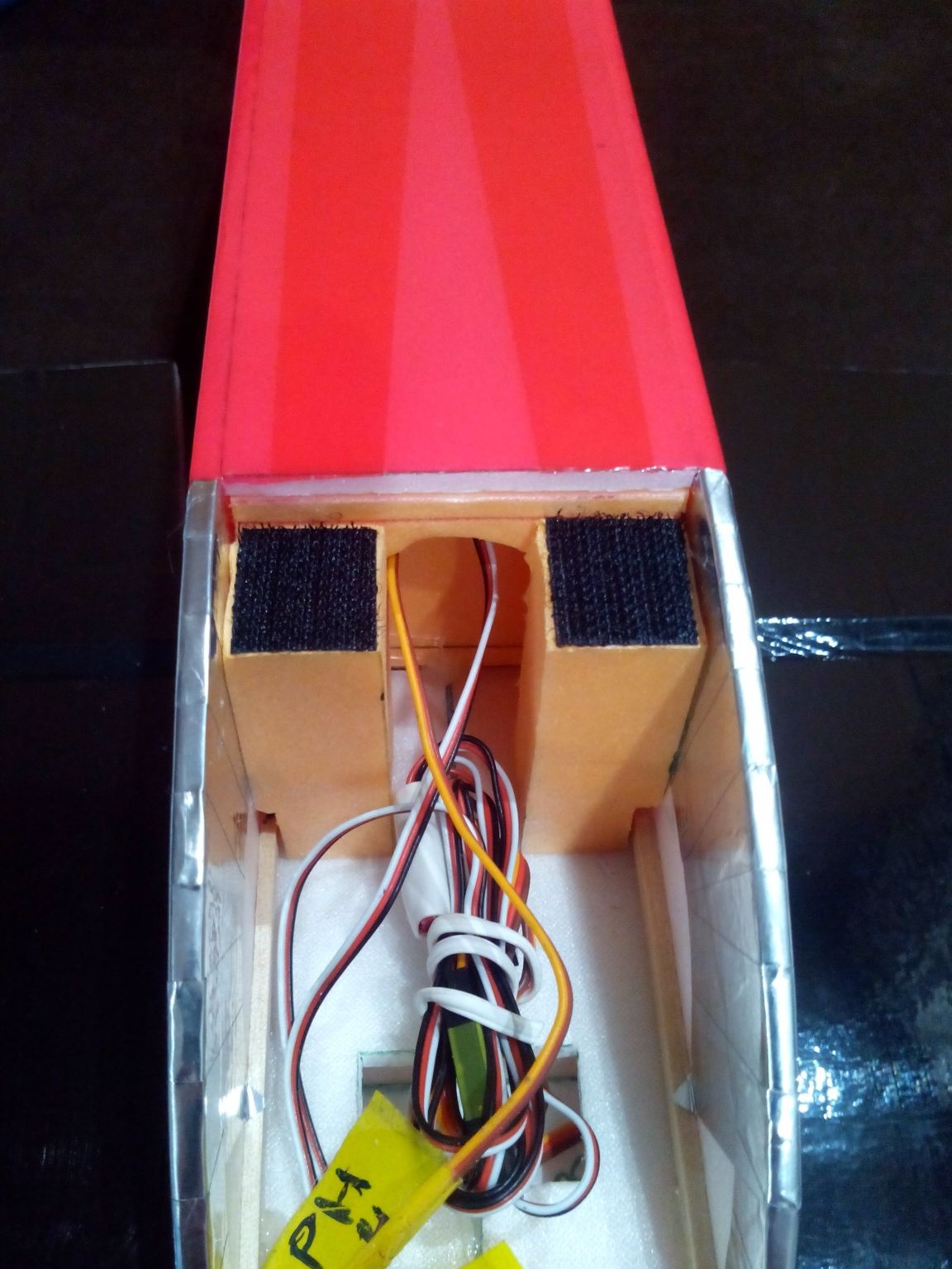
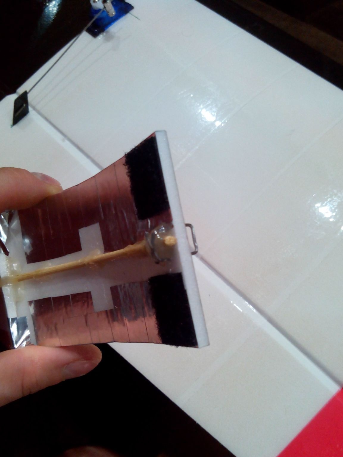
Fasten the electronics compartment cover with Velcro. To do this, glue foam blocks with Velcro halves inside the fuselage, and glue the second halves on the lid. From a paper clip we make a small handle, for which it will be more convenient to pull the lid. From the inside, the paper clip is bent onto bamboo and fixed with hot-melt adhesive.
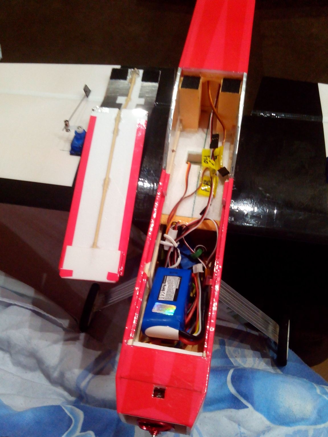
We place the rest of the electronics inside, connect all the wires and stack the battery to check alignment. The center of gravity is just one third of the leading edge of the wing.
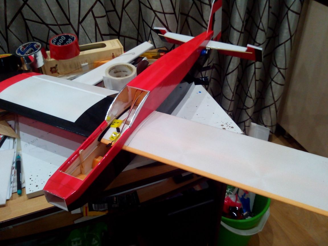
Everything, the model is ready for the first flights!
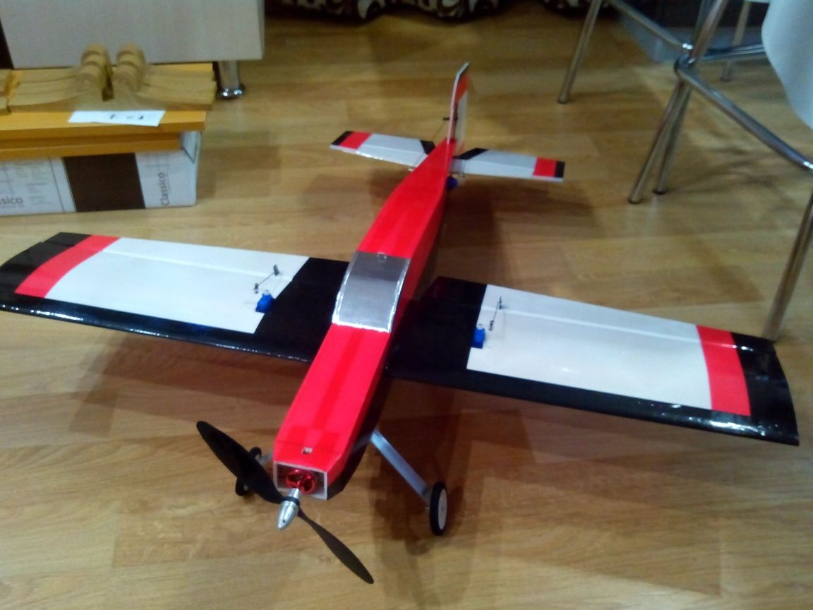
Model flight weight = 640 grams.
If you remove the chassis, you can lighten the model by 50 grams.
But even with the chassis, the model behaves very well in the air - there is enough motor for simple aerobatics.
In the future, when the piloting experience became more, I added a nose cone and a cockpit (they can be seen in the first photo), but there is no point in making them to novice pilots, since this lengthens the process of creating an airplane for at least a day.
Video of flights: