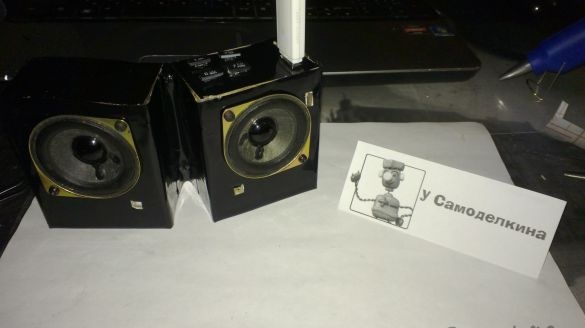
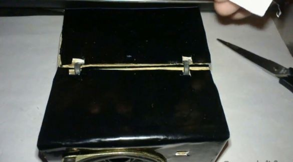
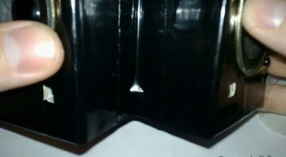
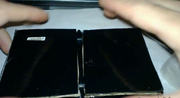
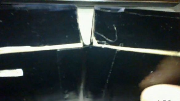
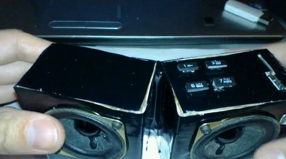
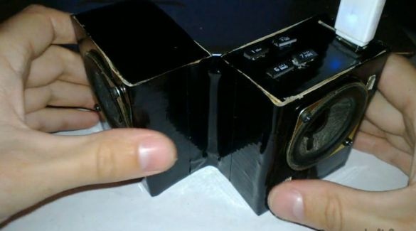
This mp3 player, not of an entirely ordinary design, was made from improvised means.
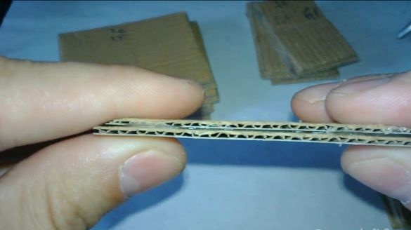
Good solution for cottages and with minimal cost. During the general harvest, a lot of rubbish was collected for discharge and something I decided to put into business). The case is made of cardboard from household appliances glued in half, which gives the structure good rigidity. Why cardboard? It’s easier to work with him and a lot of it remains after the purchase of household appliances, and in this homemade cardboard is well suited to create a cabinet.
Step-by-step assembly and demonstration of the mp3 player in the video for review
It was used:
1. Cardboard box from household appliances
2. Copper wiring from old electronics
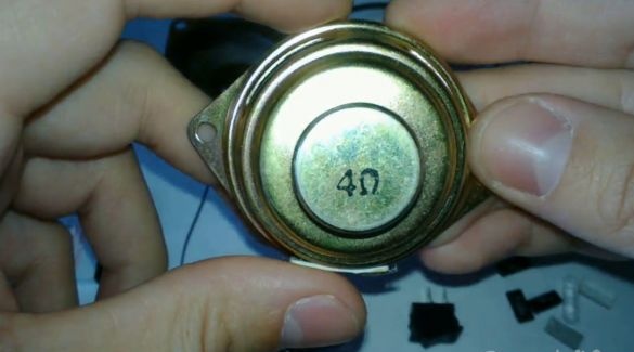
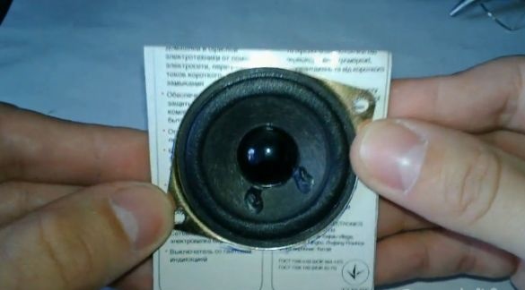
3. 2 speakers from old computer speakers
4. Keyboard from an old cell phone
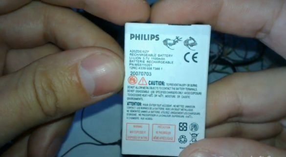
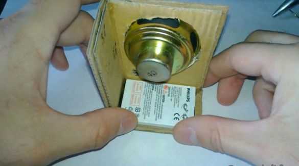
5. Battery pack from an old cell phone
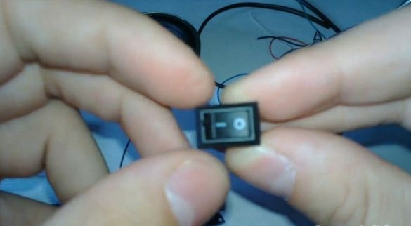
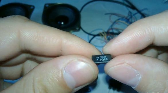
6. Switch ()
7.4 screws
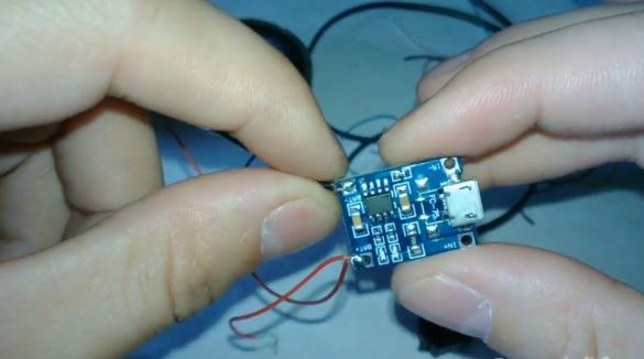
8. Battery charge module ()
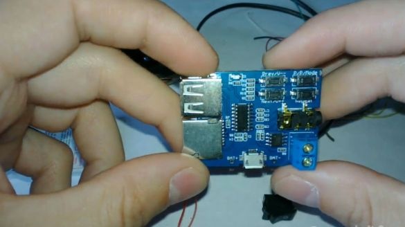
9. Mp3 player without case ()
10. Adhesive-based decorative film
11. Hot melt adhesive, super glue, electrical tape
From the tools:
1. Pliers
2. Scissors
3. Stationery knife
4. Screwdriver
5. Glue gun
6. Soldering iron (very convenient)
7. Third hand (homemade link)
Step 1
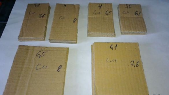
We cut cardboard into paired pieces, 4 pieces of each size.
1.4cm x 8cm, 3.6cm x 7.6cm
2.4cm x 6.5cm, 3.6cm x 6.1cm
3. 6.5cm x 8cm, 6.1cm x 7.6cm
And glue them together. This will add rigidity to the structure.
Step 2
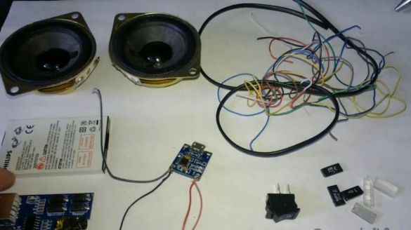
Electronicsto be used in homemade products.
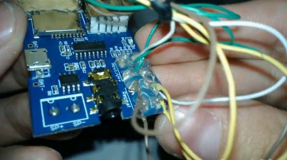
Cheap mp3 player with USB and microSD connectors (). It is powered by 5v or 3.7v from the battery. A 3W signal amplifier is already built into it. A voltage regulator is also integrated. Power connection via microUSB and two battery terminals.
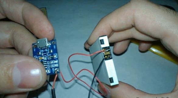
18650 lithium battery charge module on TP4056 5V 1A with micro USB interface (). It is suitable for charging batteries from cell phones.
Philips 1100mAh rechargeable battery. Pulled out of a broken phone.
Speakers from old computer speakers.
I recently ordered good quality switches () for table lamp repairs. Just one left.
And a few buttons from the keyboard of a broken phone.
Step 3
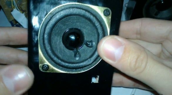
We cut out a place for the speaker so that it fits tightly in place.
We glue the base of the case, the side wall with hot glue and try on the future location of the battery. We glue on the inside with hot glue for reliable bonding.
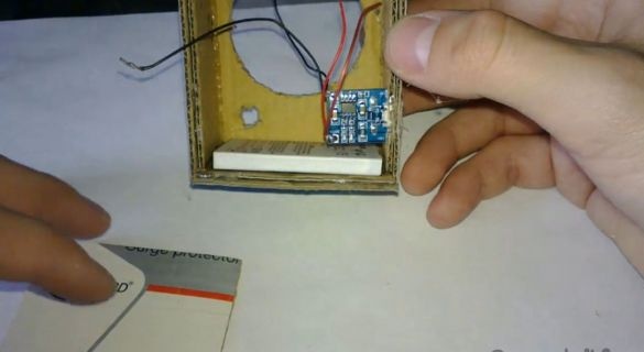
We are considering the future placement of the charge module.
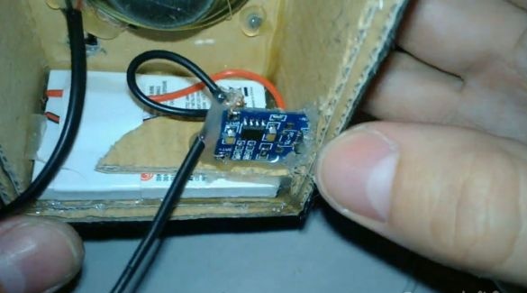
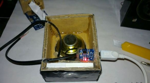
The charge module and battery will be located in the body of the second column.
The player board and control buttons will be located in the body of the first column.
Step 4
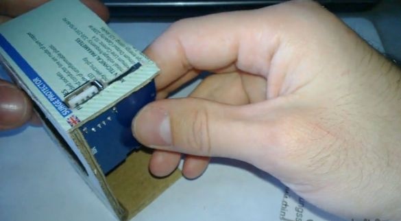
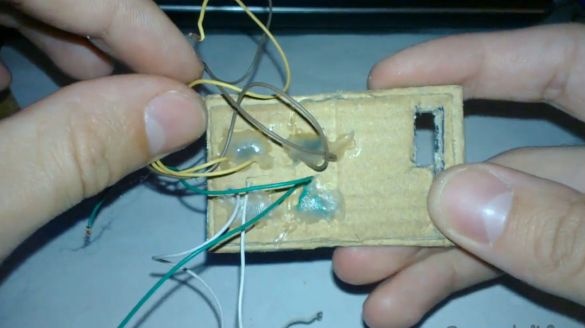
Cut holes for USB and microSD connectors on the top of the case.
We remove the regular buttons from the player board. We will place them on the same upper part of the housing for easy control.
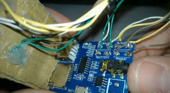
Solder the wiring to the buttons. I took 4 pairs of wires of different colors, so that later it would be more convenient to solder on the player's board.
Step 5
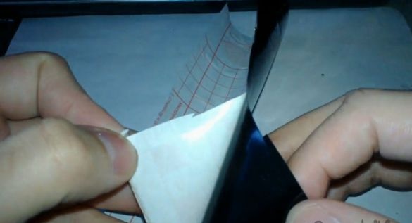
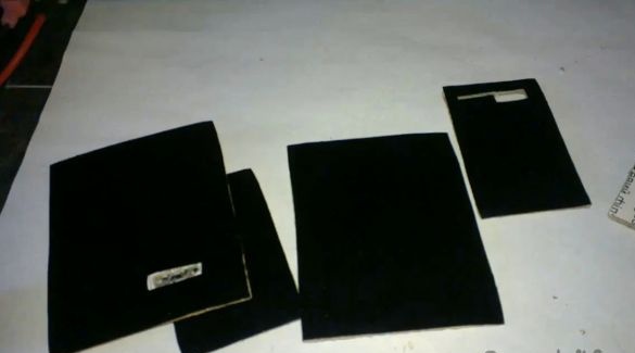
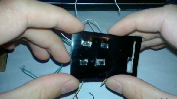
We take a decorative film on an adhesive basis (I still have black) and glue parts of the case to it.
It should be like this.
Step 6
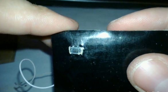
We cut a hole for the button on the top of the body of the first column and place the control button there.
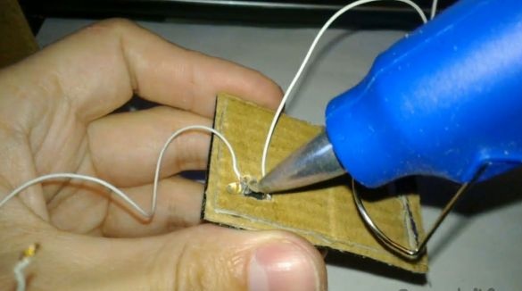
On the reverse side we fix with hot glue for reliability.
We do the same with the rest of the buttons. The 2 upper buttons will be responsible for switching tracks and volume, the lower left play / pause, and the lower right button to repeat the track. It turned out something like this.
Step 7
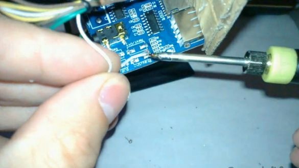
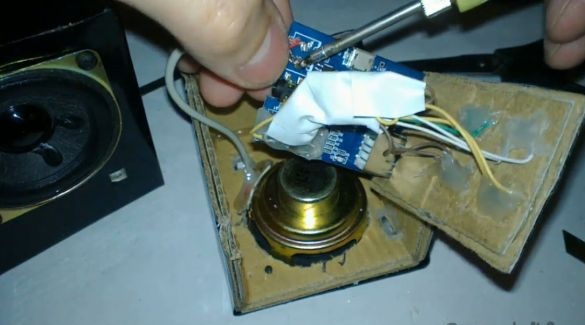
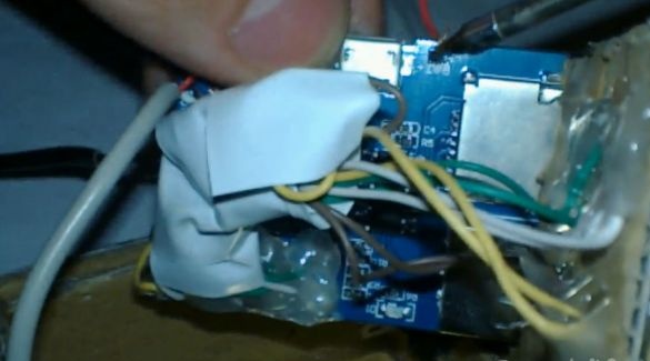
Now you can solder the wiring from the buttons to the player board.
We fill the soldering places with hot glue for reliable fixation of the wires. You can collect them in a pile and wrap with electrical tape so that they do not interfere.
Step 8
Observing the polarity, solder one pair of wires from the charge module to the battery.
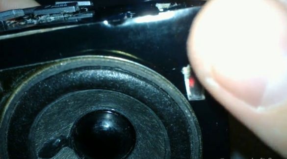
We fasten the speakers to the case with self-tapping screws and fix the self-tapping screws on the back with hot-melt adhesive.
We glue the upper part of the body and fix the charge module with hot glue for reliability.
We make slots for the wires going to the first column, fix them with hot glue from the inside and check the operation of the module before attaching the back of the case.
Step 9
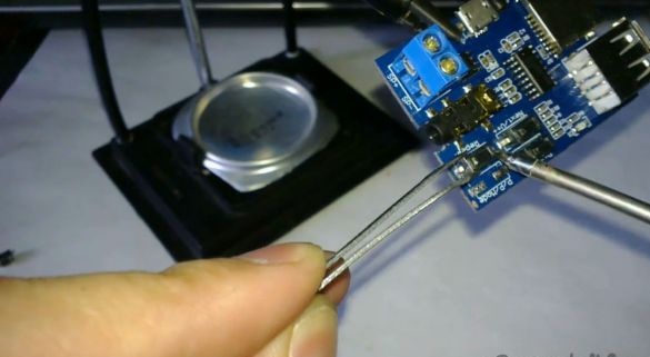
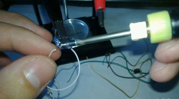
We twist the wires of two speakers and solder them to the player board observing the polarity.
Solder the power wires to the player board and to the switch. Observe the polarity!
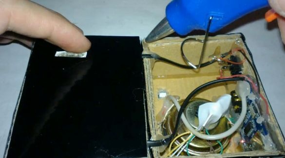
Dangling parts and wires are fixed inside with hot melt adhesive. We check the player's operation before attaching the back of the case.
Step 10
To fix the columns with each other and protect the wires, glue a wide strip of decorative film on both sides. The result was a design of the shape of the book, which gives stability and an unusual appearance to this homemade product.
We glue the buttons on the keyboard of the old phone with super glue. Be careful not to fill the control buttons with glue.
You can start the test
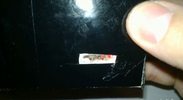
The power and player displays are clearly visible.
USB flash drives read well. Music plays loudly. At maximum volume there is a wheezing of the speakers, but the average volume is quite enough for listening.
Running on an 1100mAh battery for about 2-3 hours at medium volume when playing from USB storage devices, but there is still energy to play from microSD cards. With microSD cards it will work 2-3 times longer, since power is consumed 3v, instead of 5v.


