
The device described below is quite powerful. metal detector, he is able to detect a 25 mm coin at a depth of about 30 cm, and the maximum detection depth, according to the author, is 1.5 meters. The device can work both in the search mode of all metals and with discrimination.
Technical data of the metal detector:
- The type of device refers to induction-balanced
- The operating frequency is 8-10 kHz
- In statics there is a Pin-Point detection mode
- The device is powered by 12V
- Operating mode - dynamic
- There is a sensitivity level adjuster
- There is a threshold tone control
- Present and detuning from the ground (manual)
Depth of detection depending on the size of the object:
- The visibility of a 25 mm coin is 30 cm
- Gold ring - 25 cm
- Depth of detection of a helmet 100-120 cm;
- Maximum - 150 cm
The current consumption without sound is approximately 30 mA.
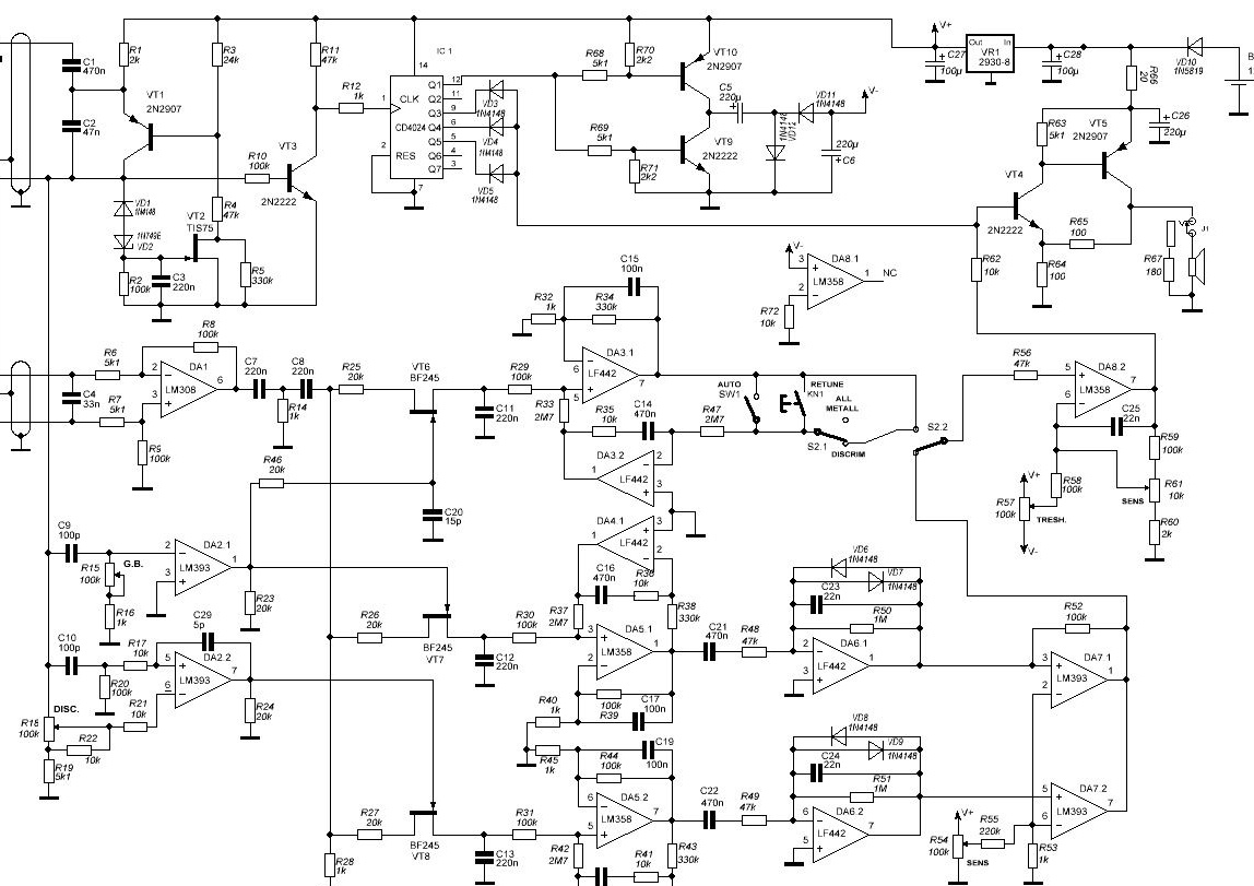
Circuit diagram:
Materials and tools for assembly:
- soldering iron;
- enameled wire 0.27 mm;
- foil;
- varnish;
- materials for creating a metal detector housing and a coil;
- wires and stuff.
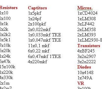
Full list electronic components can be seen in the photo.
The process of manufacturing a metal detector:
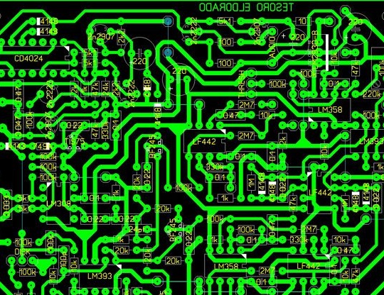
Step one. Printed circuit board
As with all metal detectors, everything begins here from the heart of the device, namely the printed circuit board. The scheme here is quite complicated, so it does not tolerate errors. Everything needs to be collected accurately and reliably, otherwise it will not be easy to find a place for the problem later.
It all starts with soldering jumpers, then you can proceed with the installation of resistors.
In addition, the author recommends using a device that can determine the capacitance of capacitors to assemble the board. Due to the fact that the device has two identical amplification channels, all parts for assembly should be as identical as possible.

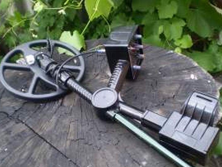
Step Two Assembling a coil for a metal detector
Since the author has already prepared the case for the metal detector, at this step you can only see and understand what kind of coils work and what they should be.
The DD sensor is made in the same way as for all balanced-type metal detectors. The TX transmitting coil has 100 turns of 0.27 mm wire, and the RX receiving coil has 106 turns.
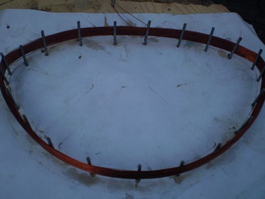
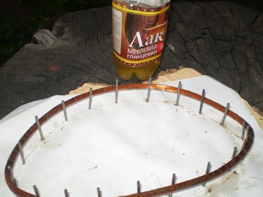
When the coils are wound, they need to be wrapped with threads and well soaked with varnish. Further, when the varnish dries, the coils should be tightly wrapped with electrical tape.A foil is used as shielding, it must be wound all over the coil, leaving a distance of 1 cm between the end and the beginning of the foil in order to avoid a short circuit.
The coil can also be shielded with graphite, for this graphite is taken, mixed with nitro-varnish in a ratio of 1: 1 and applied to a 0.4 mm thick wire pre-wound without gaps on the coil. The wire connects to the cable screen.
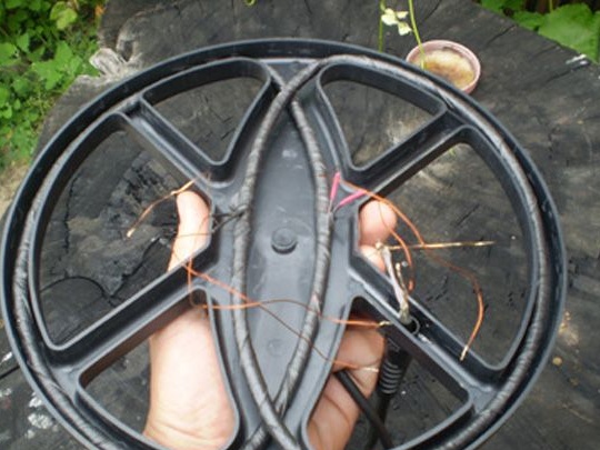
Step Three The final stage of assembly
Now the coil can be installed on the body and balance the eye. As a test you will need ferrite, it should have a double beep, and a single coin. If the opposite is true, the terminals of the receiving winding must be interchanged.
The author tunes each coil in frequency separately, and it is very important that there are no metal objects nearby. To adjust the coils, a prefix for measuring resonance is used. The prefix must be connected to the detector board parallel to the transmitting coil and measure the frequency. By selecting a capacitor, it is necessary to achieve a frequency of 600 Hz higher than in TX.
When the resonance is matched, you need to assemble the coil and see if the device sees the VDI scale, starting from aluminum and ending with copper. If the entire scale on the device does not work, then you need to select the capacitance of the resonant capacitor in the RX circuit with a step of 0.5-1 nF. As a result, the device should see foil at a minimum of discrimination, and copper at a maximum.
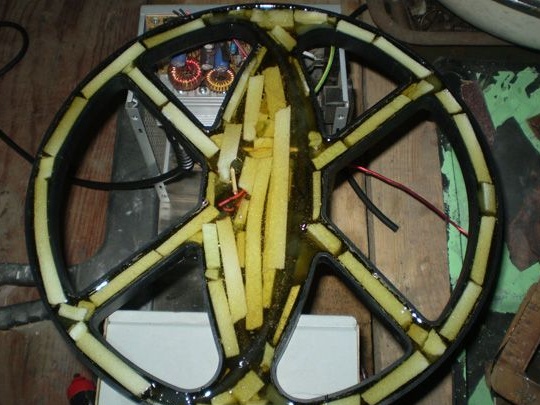
In conclusion, the coil is finally fixed with hot melt adhesive. To facilitate it, the author seals all voids with foam. It also needs to be put on hot melt glue, otherwise it will pop up after pouring. Well, then the whole thing is filled with epoxy.
Filling the first layer, you need to leave a distance of 2-3 mm from the top. Next, a second layer of resin with tint is poured. Aniline dye, which is used to dye fabrics, is excellent as a color. To mix the components, the dye must first be mixed with the hardener, and then the hardener must be mixed with the resin, otherwise the dye does not mix.
At the end, you can collect the board and connect all nodes. For testing, you need to connect the power and go to all points where it should be.
Next, you need to check the discriminator. Turning the knob, all metals should be cut in turn, starting from aluminum, ending with copper, but copper should not be cut. If everything works this way, then the device is assembled correctly. The scale should be made so that it fully fits into the radius of rotation of the handle of the discriminator, and this is done by selecting C10. If the capacitance of the capacitor is reduced, the jackal will stretch, if increased, then vice versa.
Still worth a few words about the cable, the author has four wires. Two wires go to the transmitting coil and two to the receiving coil, but the screen is connected to the housing.