
An acoustic switch is a very useful and necessary thing in the household, especially if you want to automate some devices or lighting in your home and add creativity to your home! With the acoustic switch, you can turn the lights on and off or use it for other appliances, such as an electric kettle or fan.
This scheme is fully operational, streamlined and stable. There are many schemes of similar devices on the Internet, but when they are assembled, there are a lot of problems with working capacity, and some of them have long discussions at the end of which, the problem is often not solved. Below is the diagram itself.
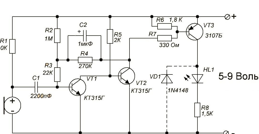
The circuit is powered by a voltage of 5 to 9 volts, so choosing a power source is not difficult. You can use for example the crown or other batteries and accumulators. If you need stationary power, then the network has many power supply circuits, even a transformerless one will do.
The printed circuit board is made for DIP components, but despite this, it is quite compact in size and choosing a case for it will not be difficult. You can download the printed circuit board at the link:
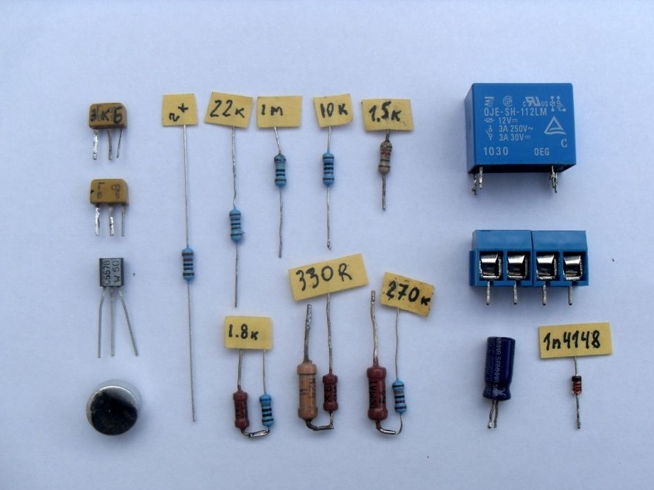
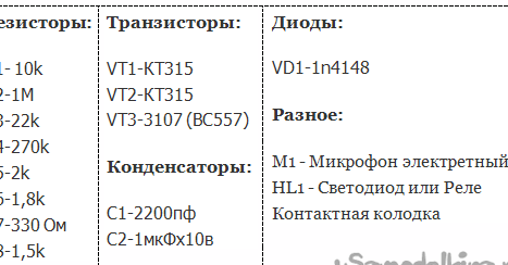
Parts List for Assembly
PCB manufacturing
I will not explain in detail how to make a printed circuit board, as this will take a lot of time. The circuit board file is opened using sprint-layout 6.0:
The circuit uses the diode VD1, it is needed to protect the transistor VT3 from the EMF of the relay coil. If you will connect a relay as a load, then you need to put the diode, if a light load will be used, then you can put a jumper instead.
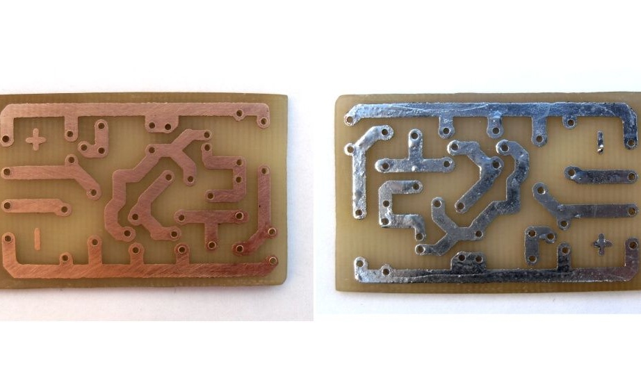
After making the circuit board, in order to avoid oxidation, pour the tin to the nut. Open the sprint-layout 6.0 program and solder all the details on it according to the location. If everything is done correctly, the details and ratings are not mixed up, then the device should work right away without any problems.
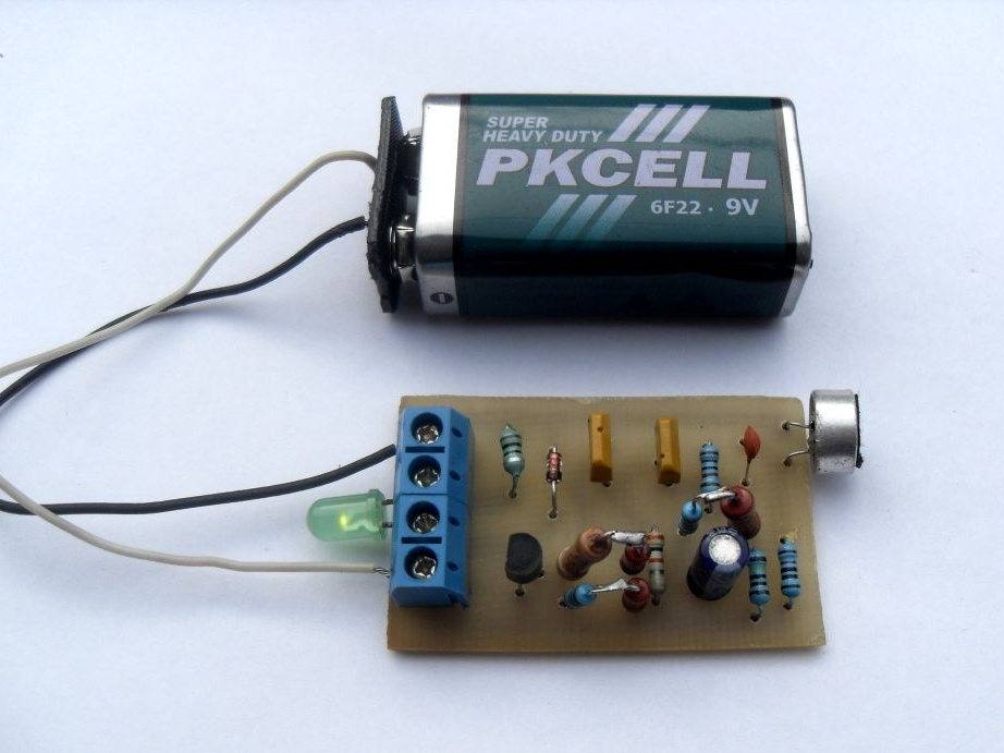
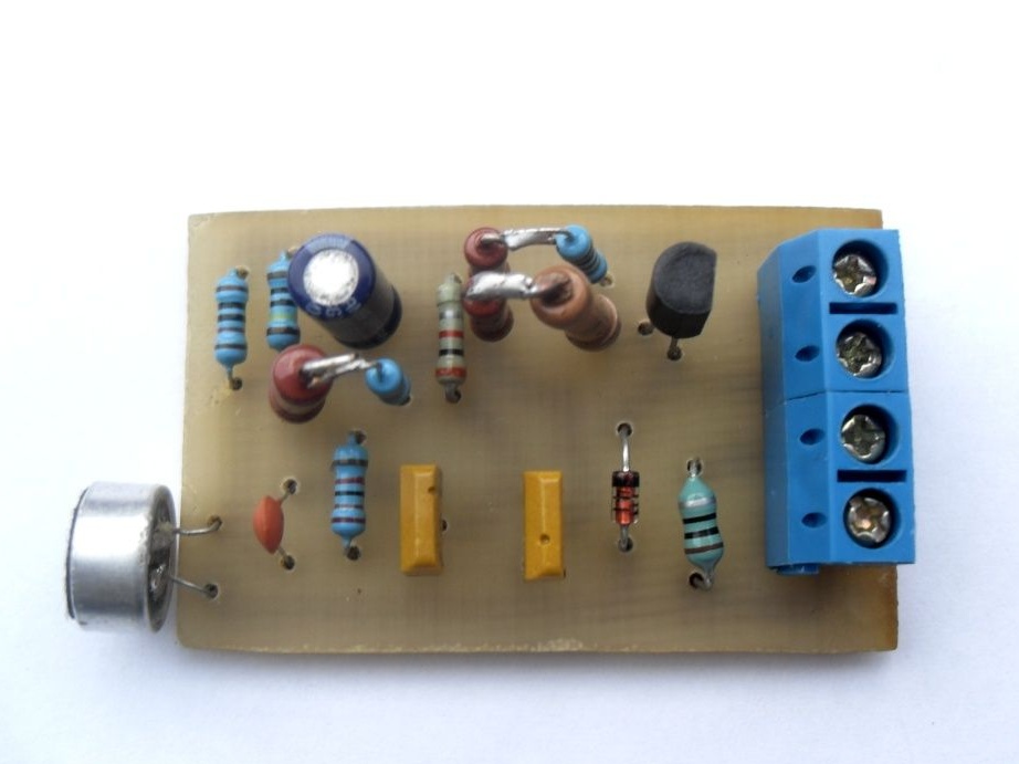
This is what the assembled acoustic switch looks like.
And another photo with the connected battery and LED on the load.
I would like to say about one problem that may arise. In the circuit there is a 1.5 kΩ R8 resistor, if you use an LED as a load, you can leave it, if you plan to install a relay, then replace the resistor with 2 Ohms. More problems should not arise))
As a result, it turned out not an expensive but very effective and useful device that will certainly find its application in the household! )))