
Hello to all electronics lovers. In this article I will tell you how to make a search engine robot that travels along a black line, which you can draw as you like. I am sure that this kit kit will be a very interesting toy for those who will collect it.
I won’t pull for a long time, we’ll go straight to manufacturing.
Before reading the article, I propose to watch a video with a detailed assembly processor for this kit kit, as well as its performance checks.
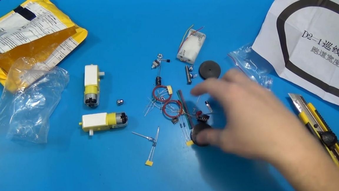
In order to make a search engine robot that will travel along the black line do it yourself, you will need:
* Kit
* Soldering iron, solder, flux
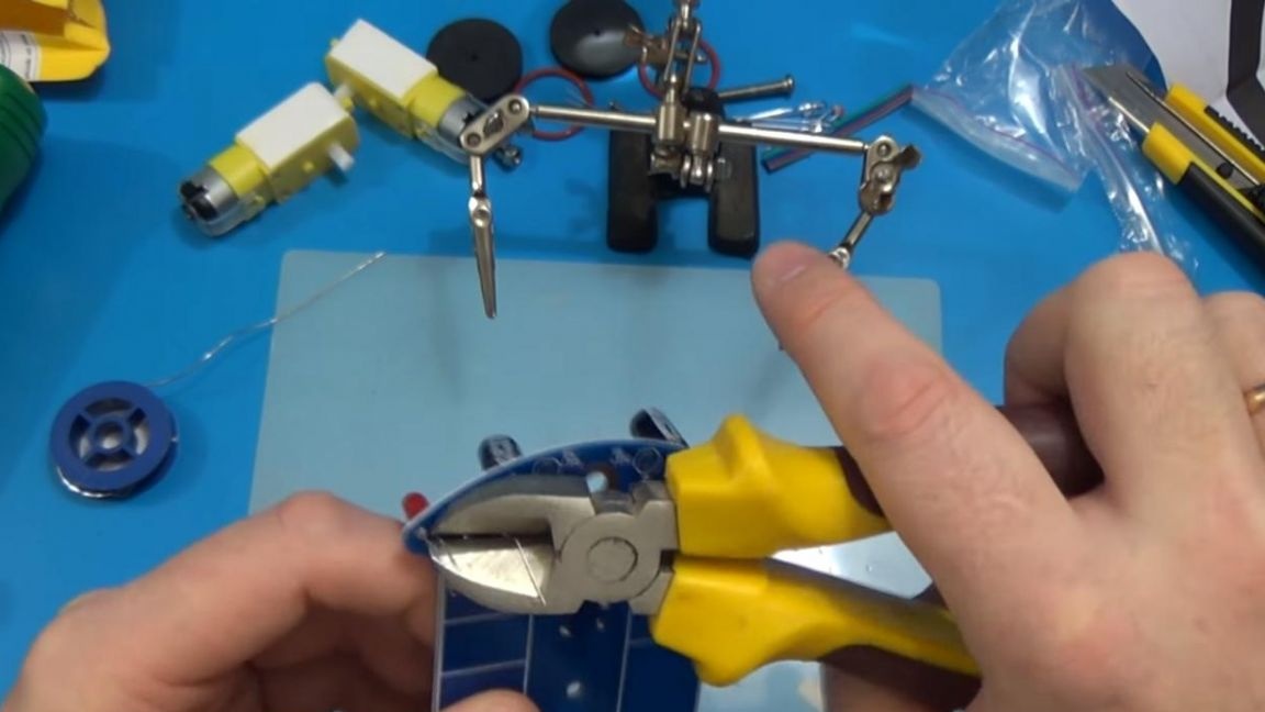
* Side cutters
* Multimeter
* Device for soldering "third hand"
* Pliers
* Phillips screwdriver
Step one.
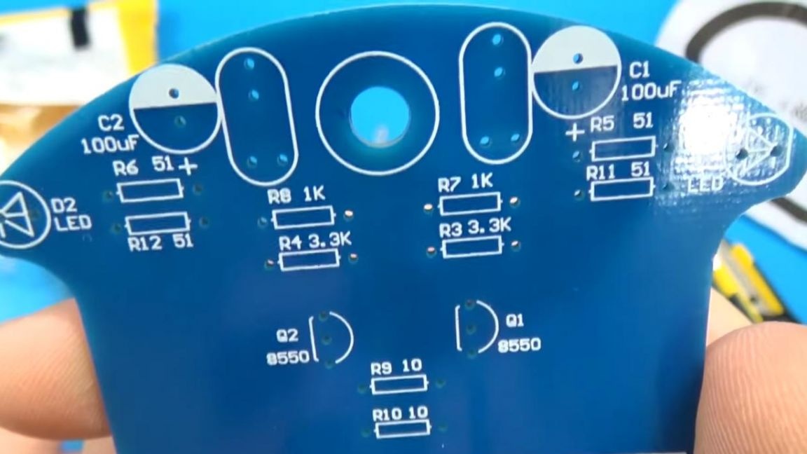
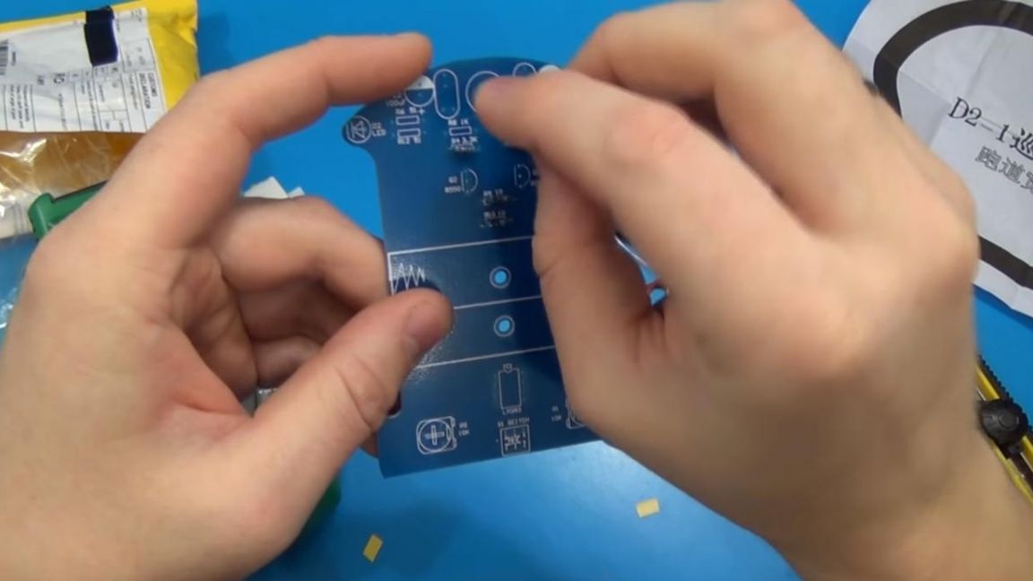
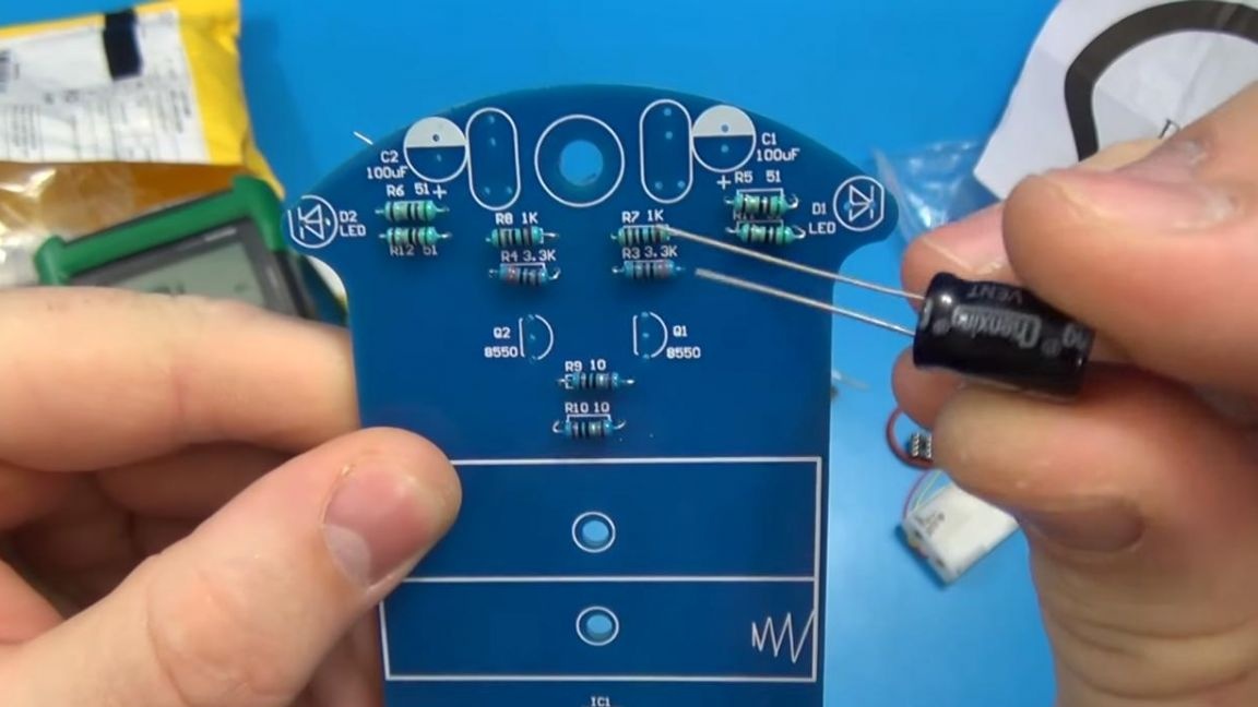
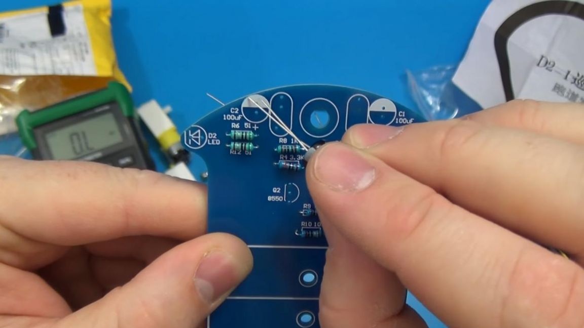
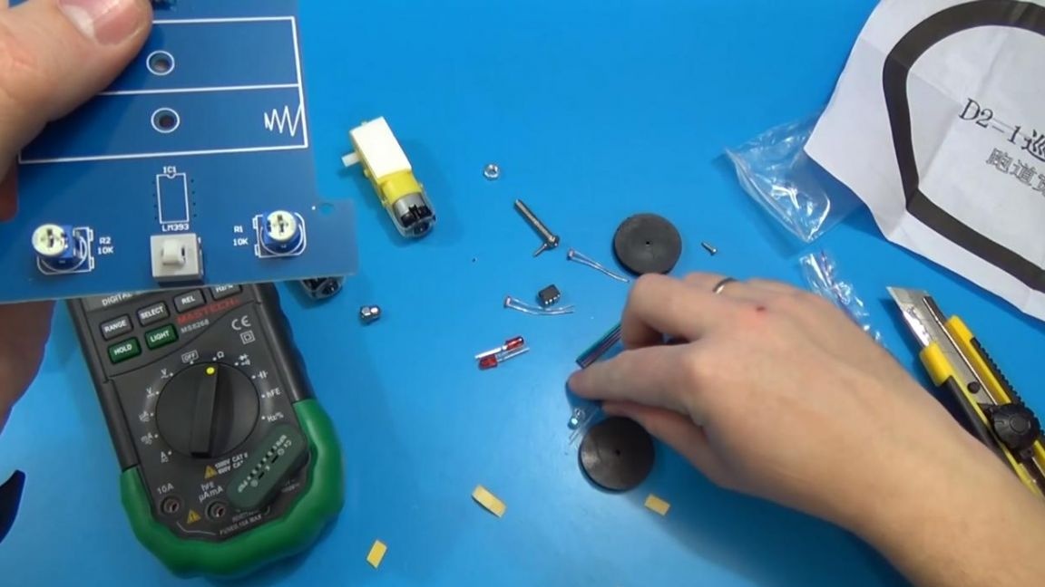
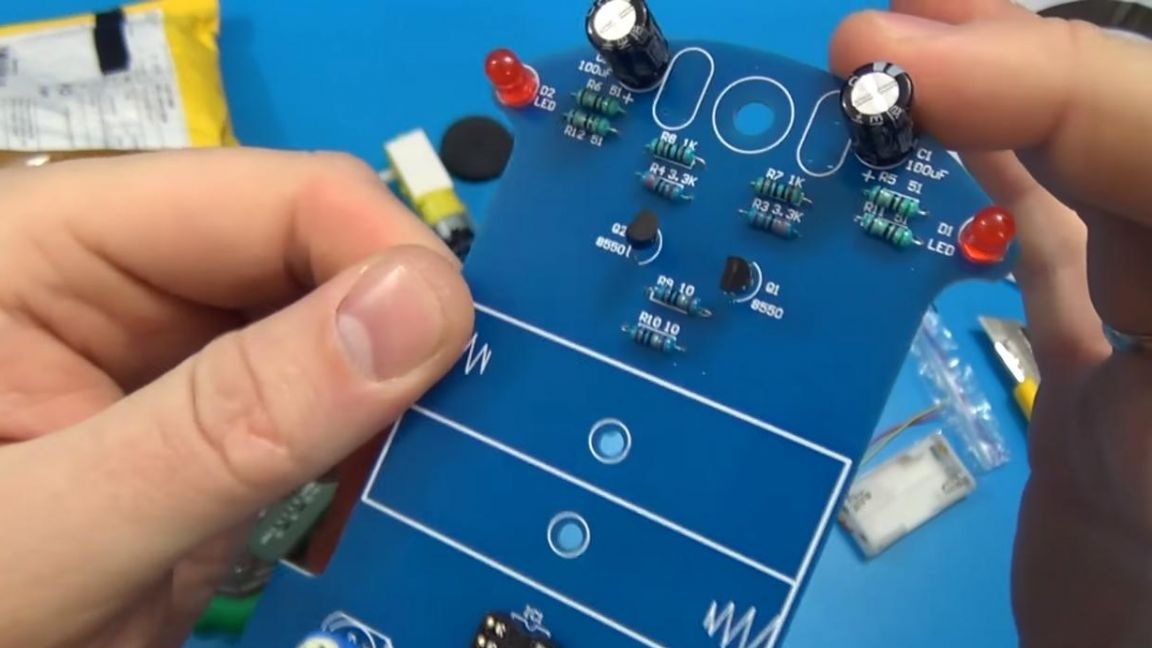
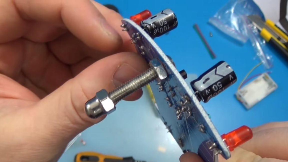
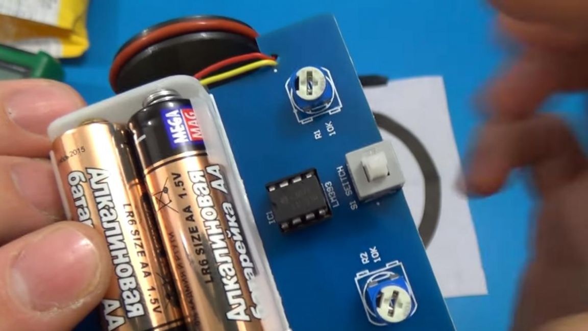
First of all, you need to place all the components on the board, the kit includes both resistors, capacitors, and transistors.
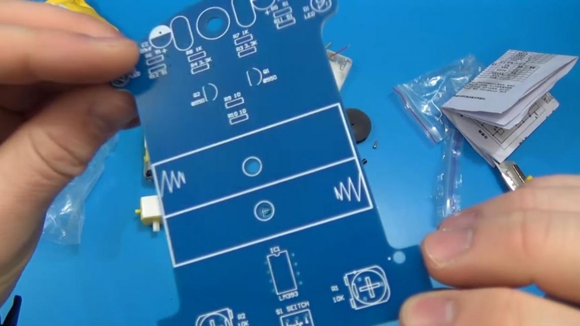
First you need to install the resistors in their places, the nominal value of which is indicated on the board, while the resistors themselves are color-coded, by which you can determine the resistance of a single resistor. Also, resistance can be measured with a multimeter, this method will be faster, but this does not mean that it is a must. We arrange the resistors on the board according to their nominal value, slightly bend the terminals on the reverse side, this is done so that they do not fall out when soldering.

Step Two
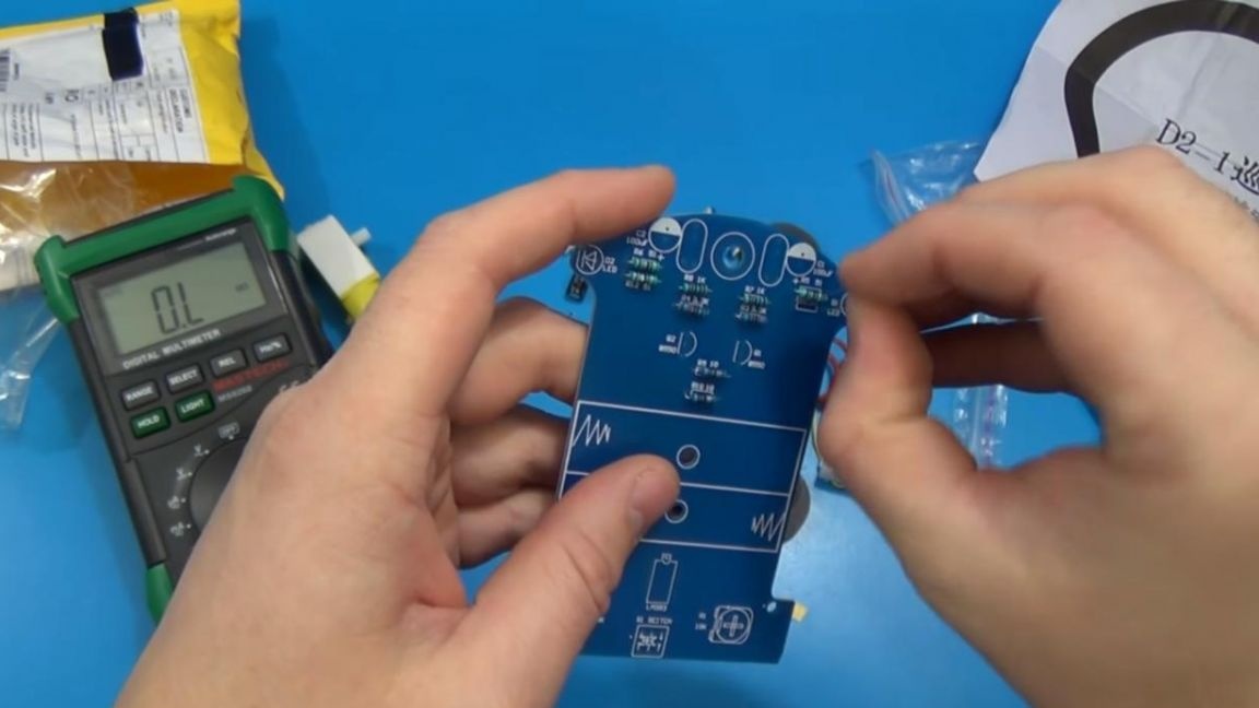
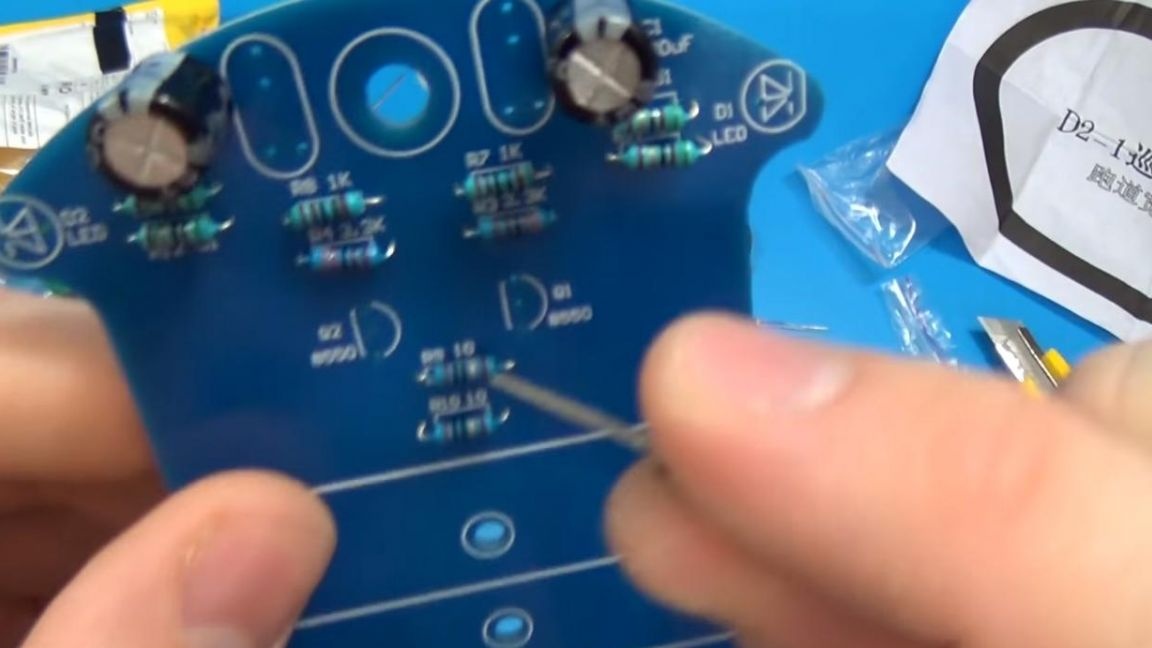
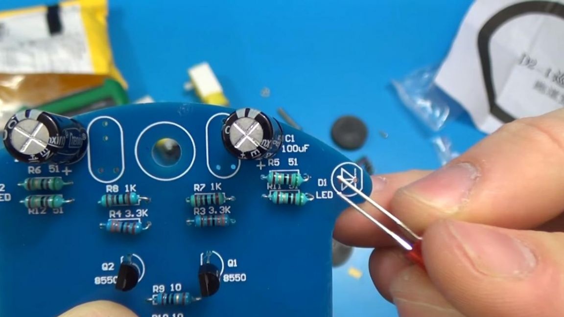
The resistors are all in place, followed by the capacitors, unlike the previous components, these have polarity. The minus of the capacitor is indicated on its case by a white strip with a dash, on the board the minus is indicated by a filled white semicircle.
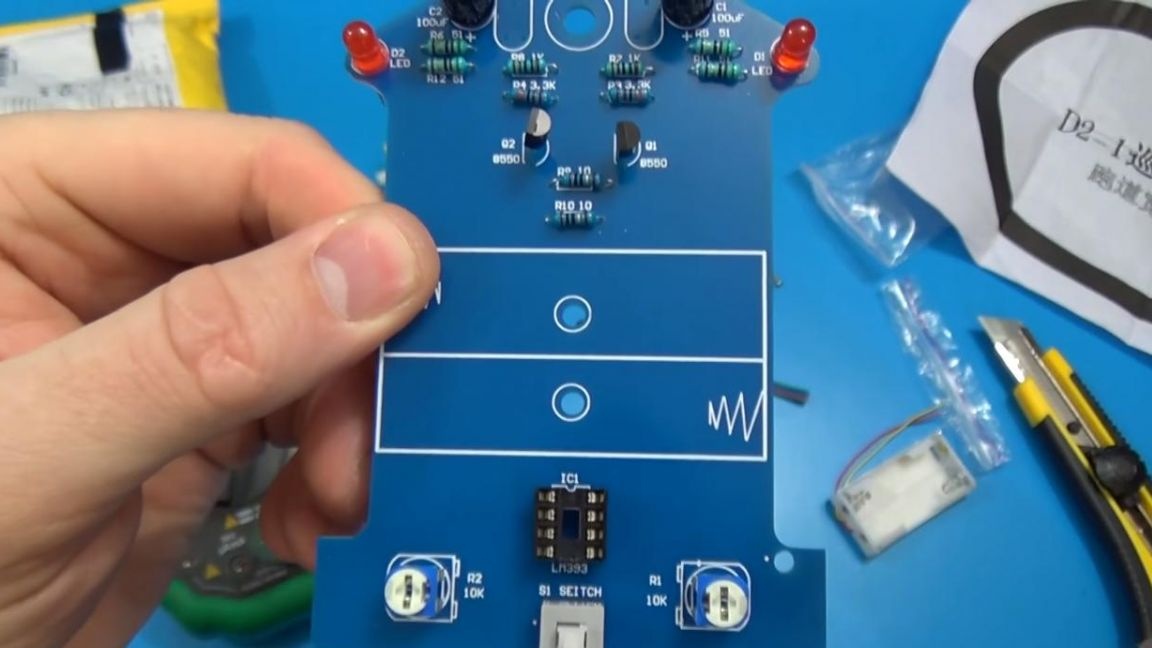
When the capacitors are in their places, we turn to the transistors, they are the same for us, so we can’t mix up with each other. To properly position them on the board, you need to combine the flat part of the transistor with a dash on the board.
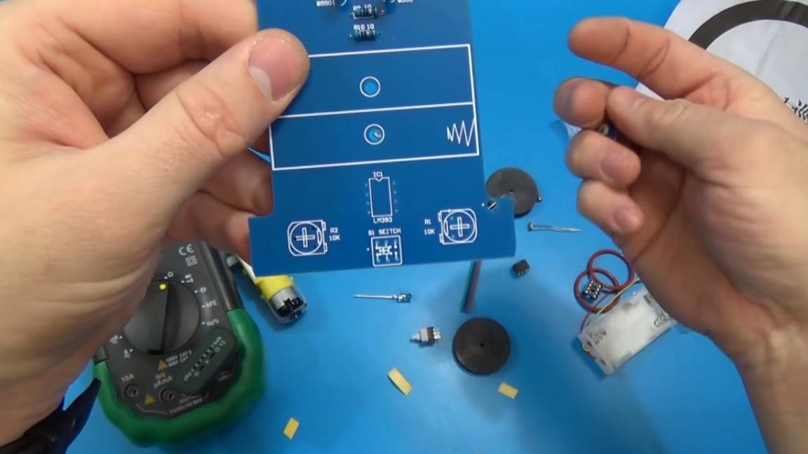
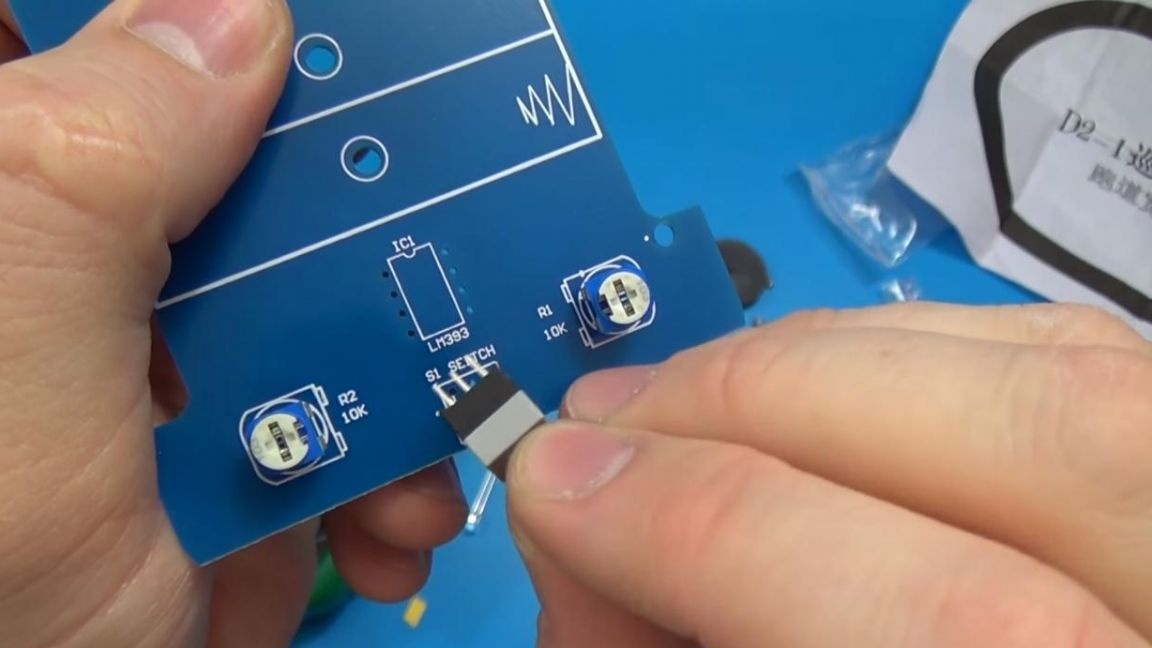
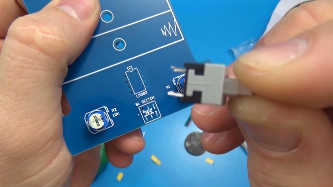
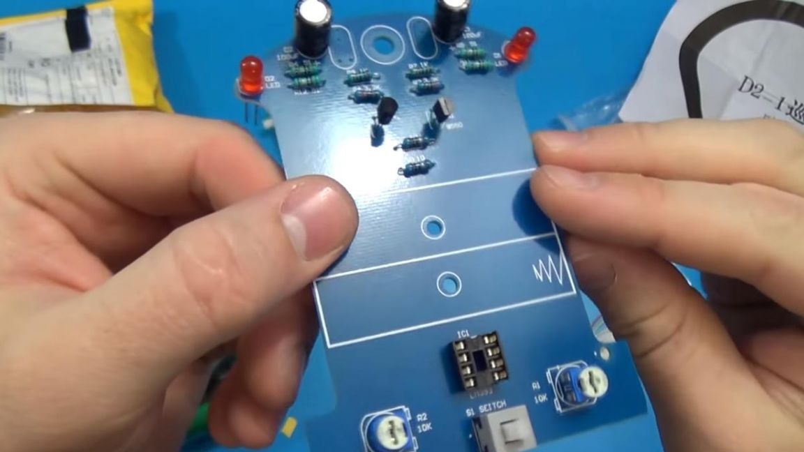
Then we install two tuning resistors, in connection with the location of the terminals it will not work to put them incorrectly, which is good. We also place the power button, it is on-off, that is, it can be in the on or off position, its correct location corresponds to the coincidence of the position of the strip on the button itself with a point on the board.
Step Three
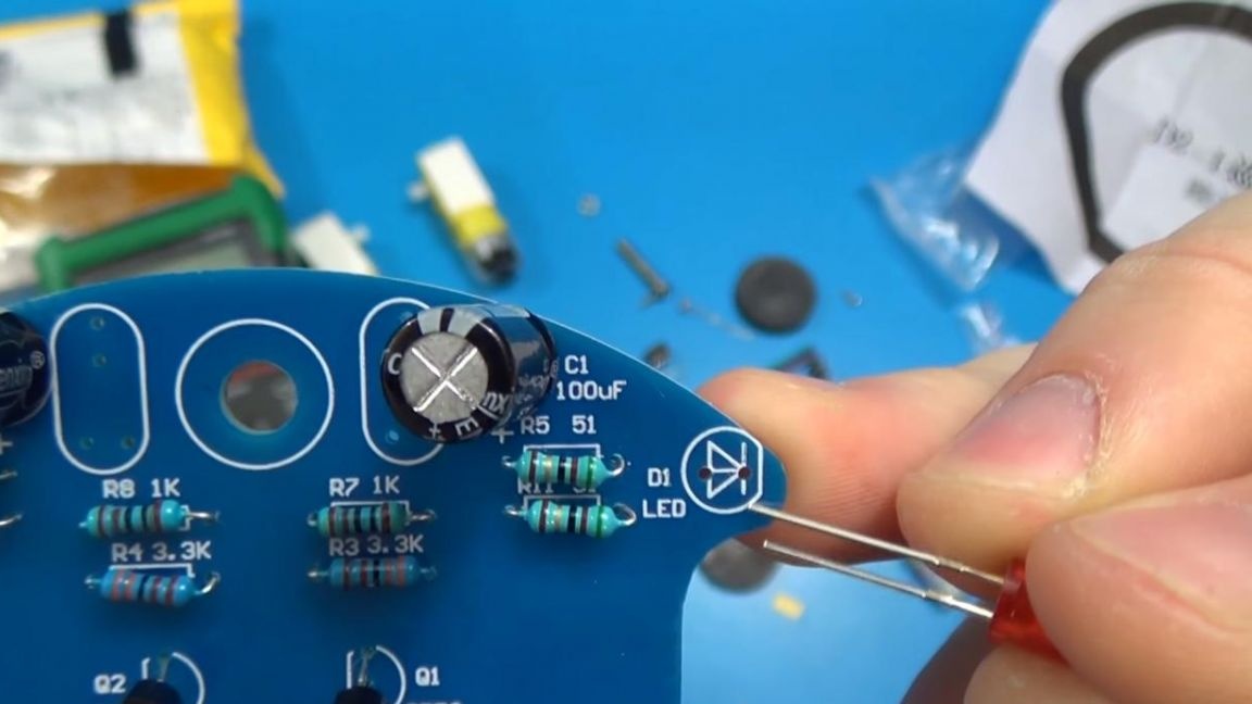
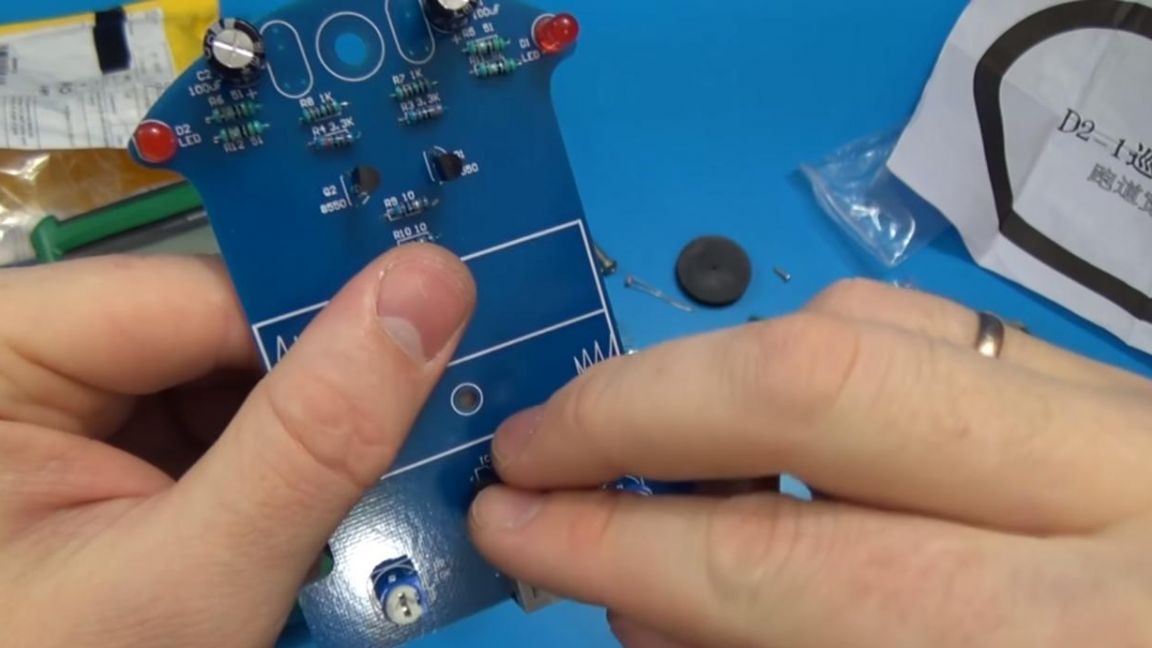
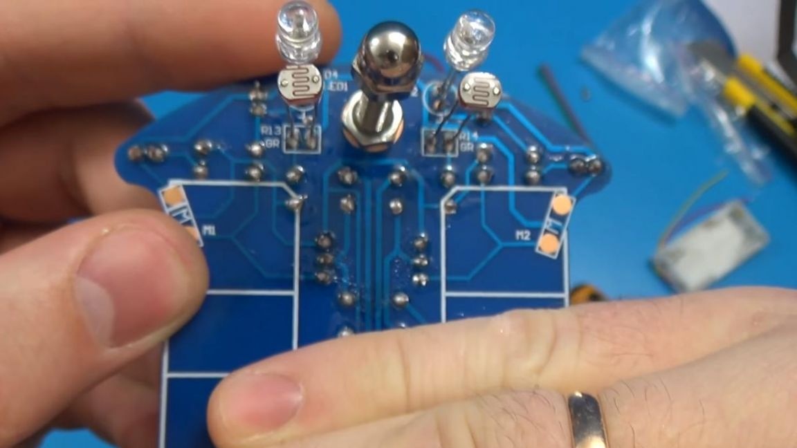
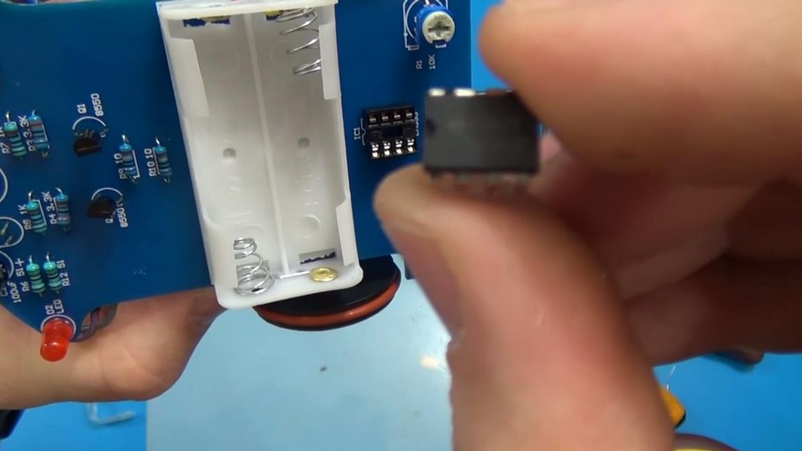
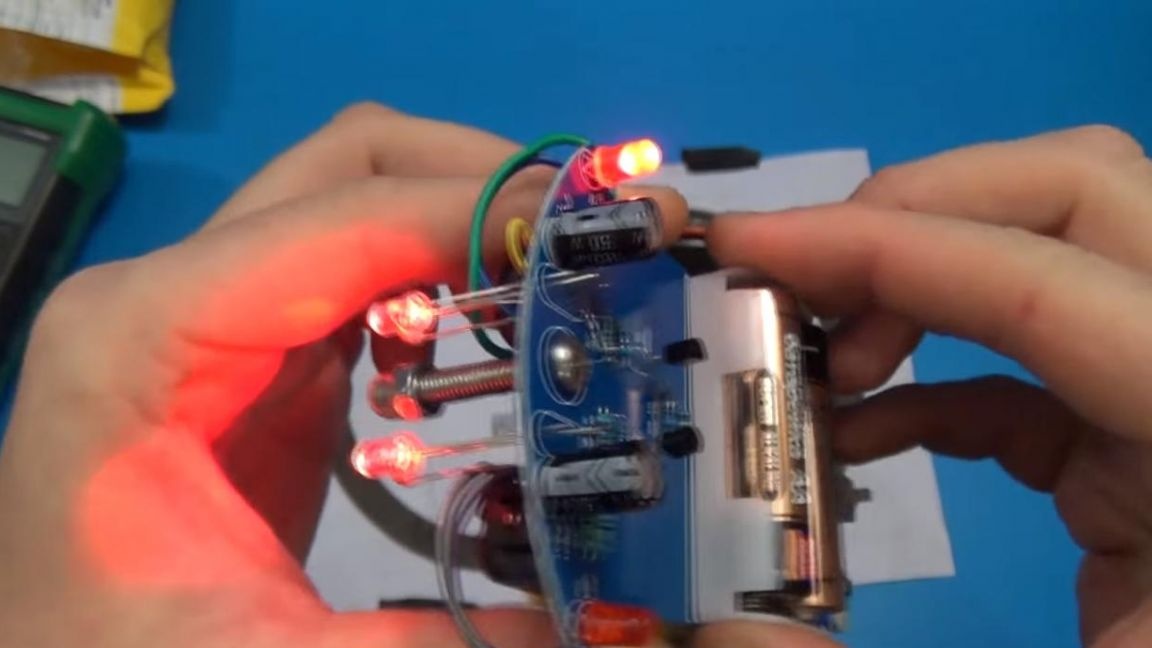
Time to deal with LEDs, there are four of them in the kit, two red and two white. On the board, the plus is indicated by a triangle, on the LED it is a long output, with a minus everything is clear. We place the red LEDs on top, they are analogues of the "turn signals".There is a separate place for the microcircuit, we insert the connector there, so replacing it in which case will be much easier, but the contacts will not overheat when soldering.
Step Four
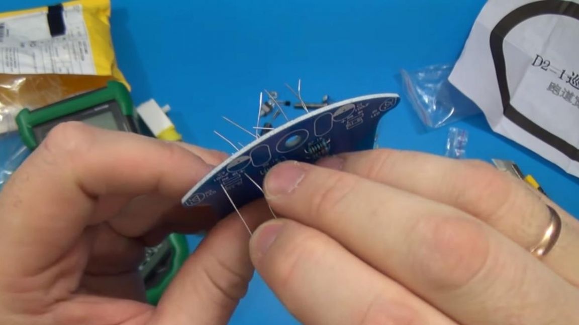
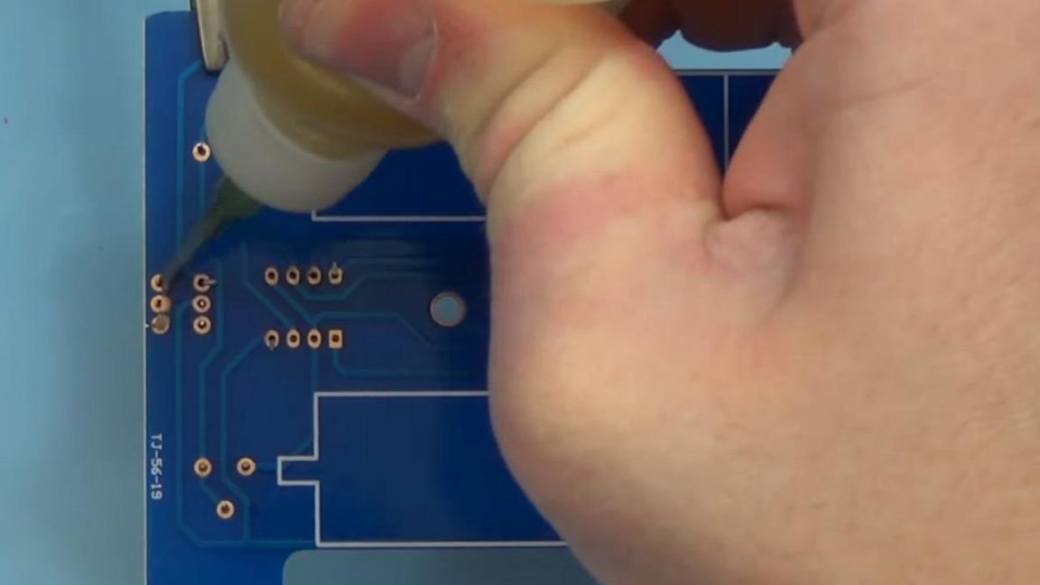
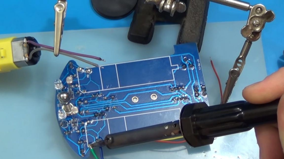
It’s time to solder the components placed on the board, we fix it in the soldering device “third hand”, apply the flux and solder, slightly feeding the solder.
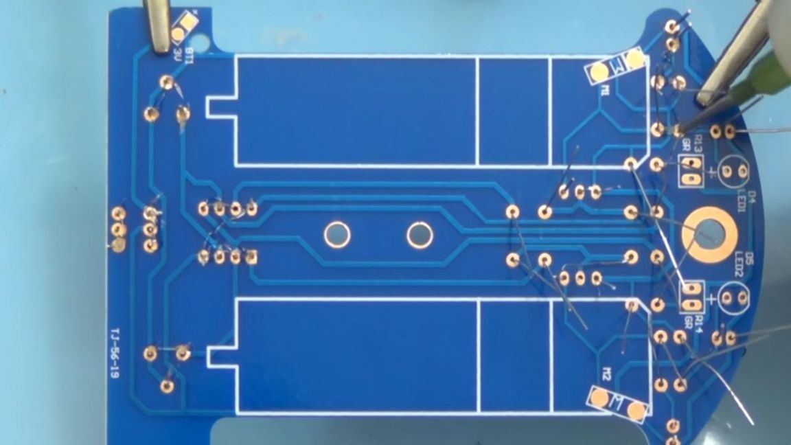
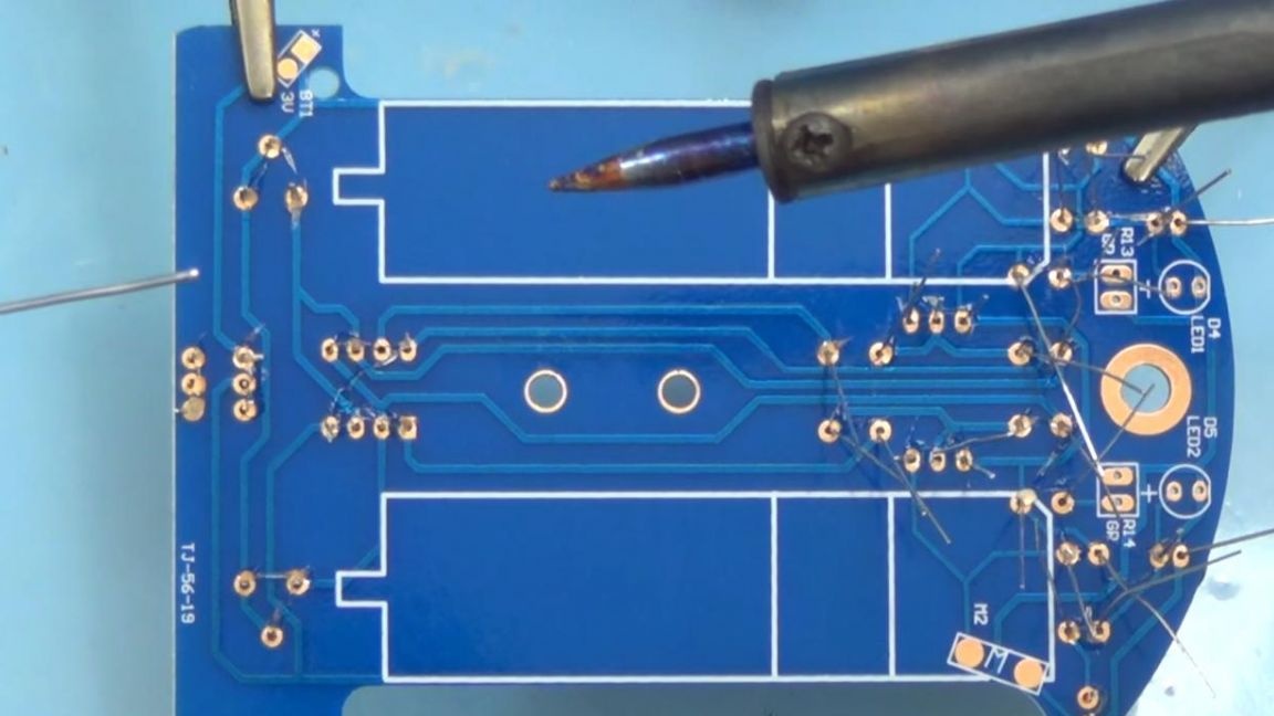
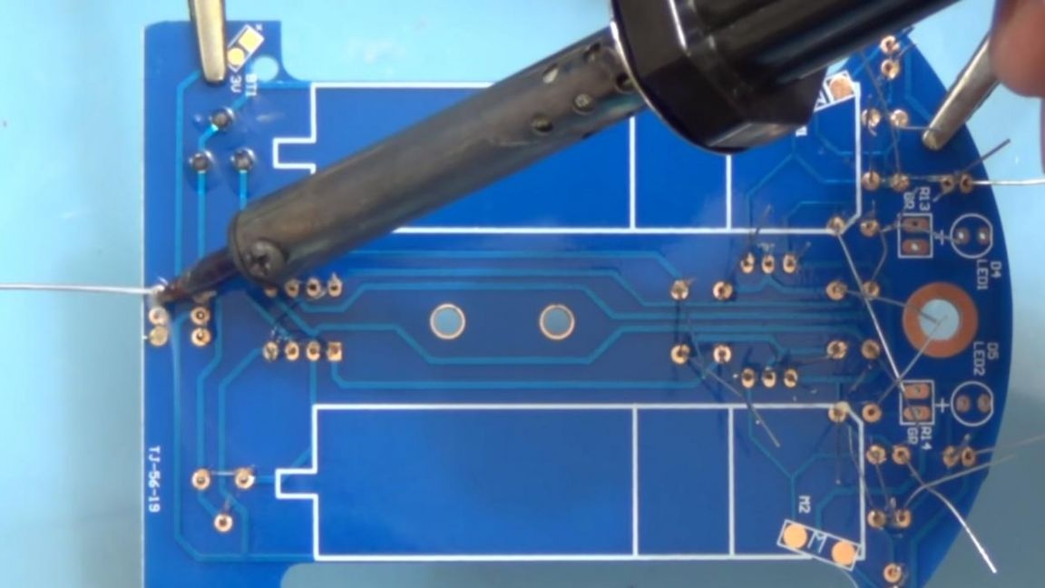
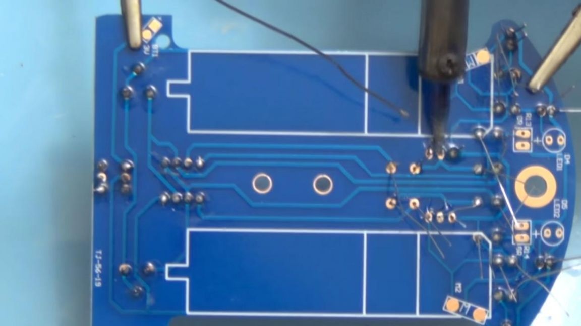
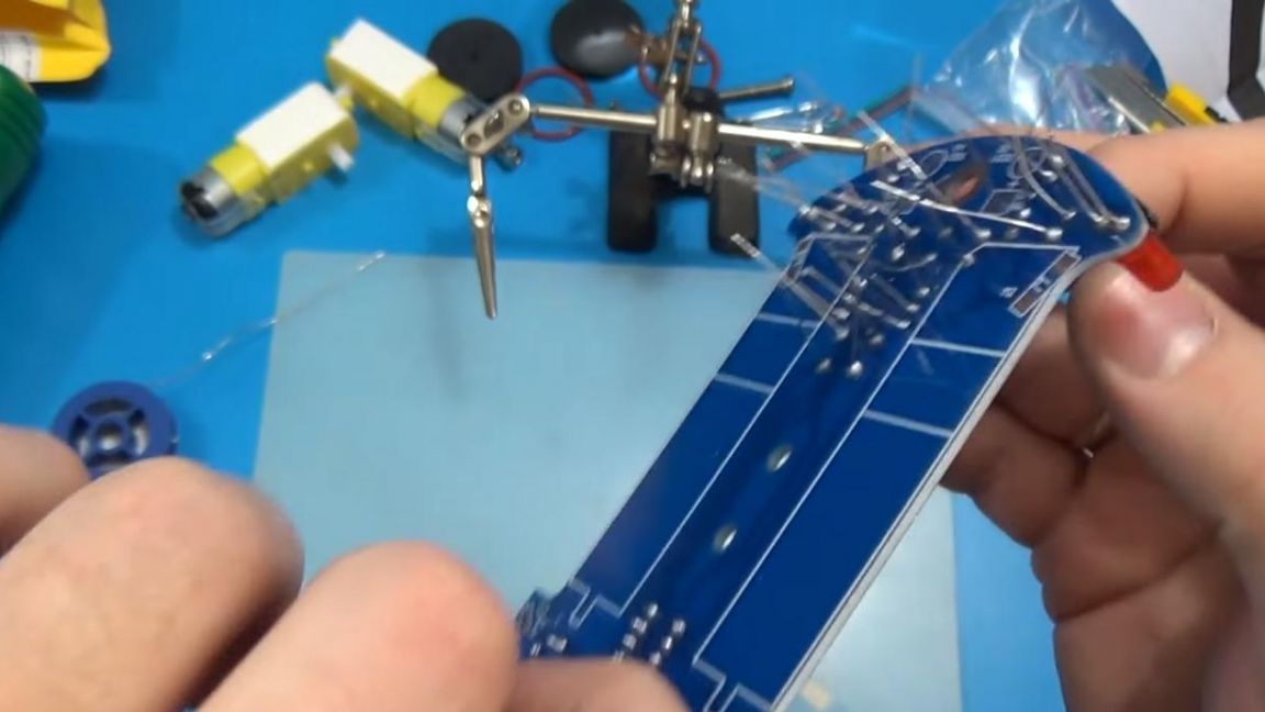
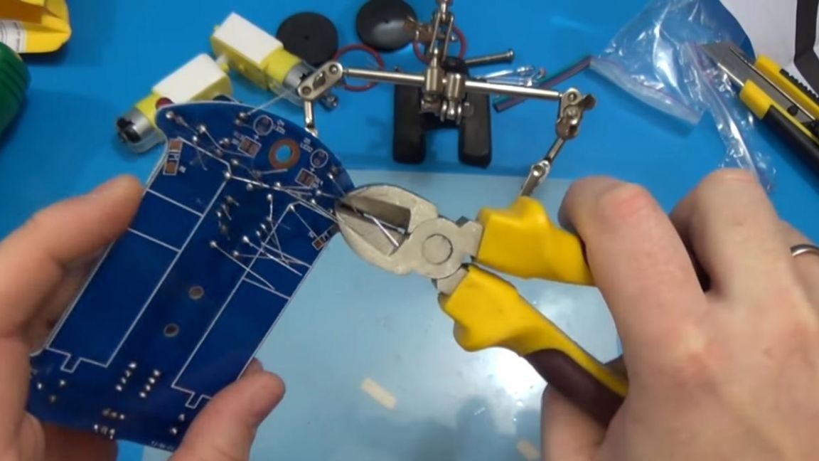
After soldering, we remove the remnants of the conclusions with the help of side cutters, but be careful with this, since tearing off the contact pads, as well as the tracks themselves, is easiest at this stage.
Step Five
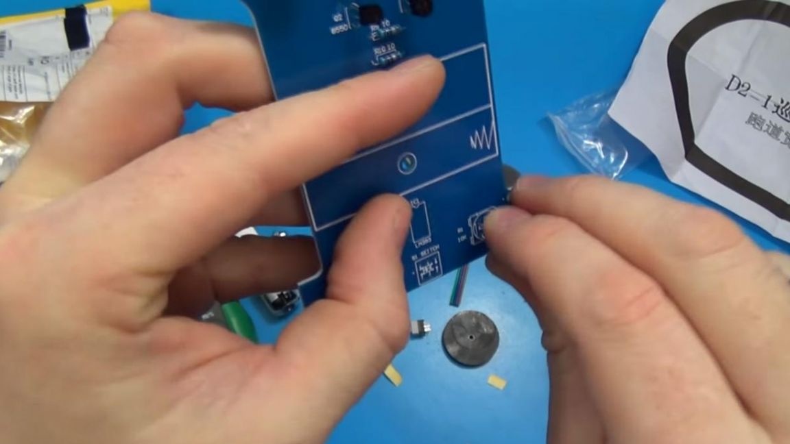
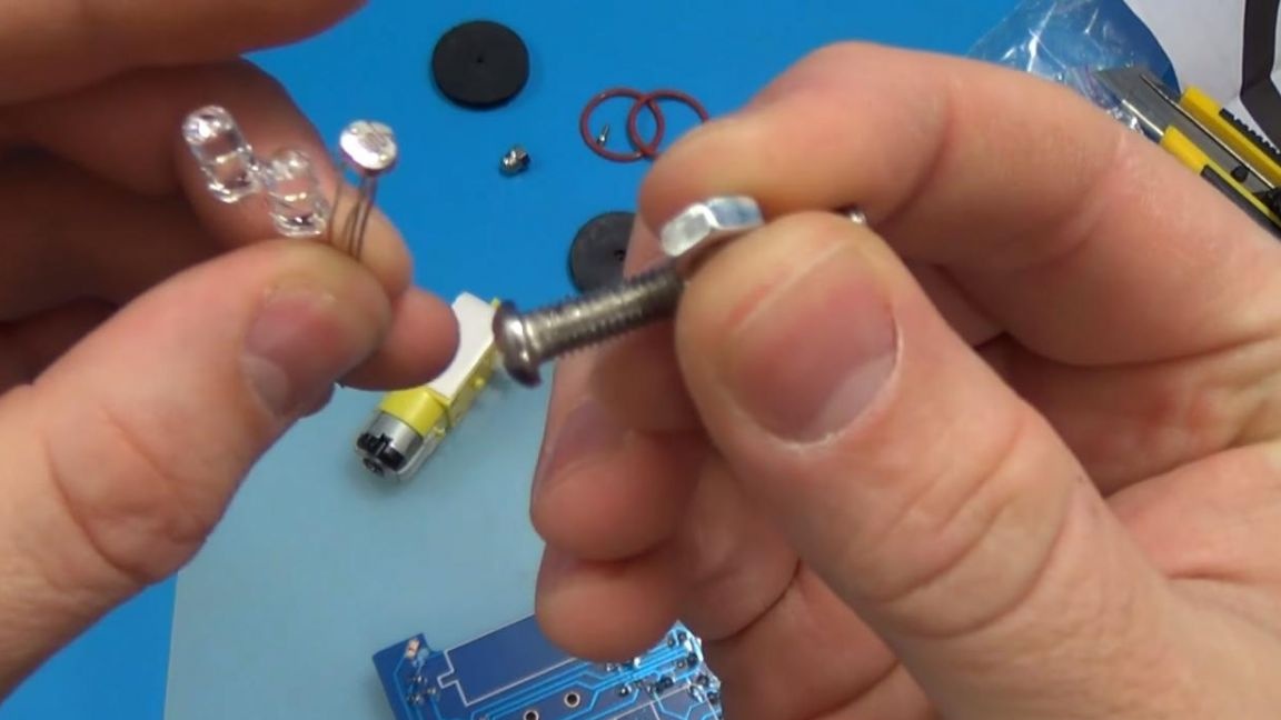
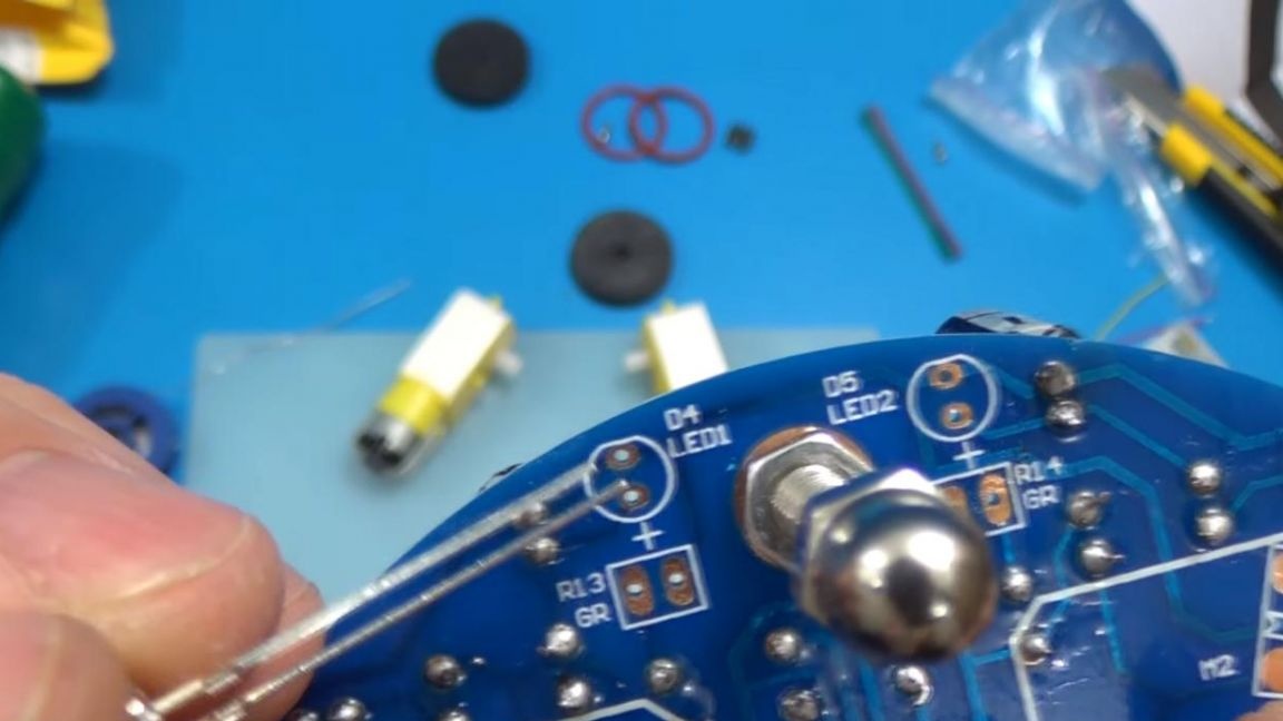
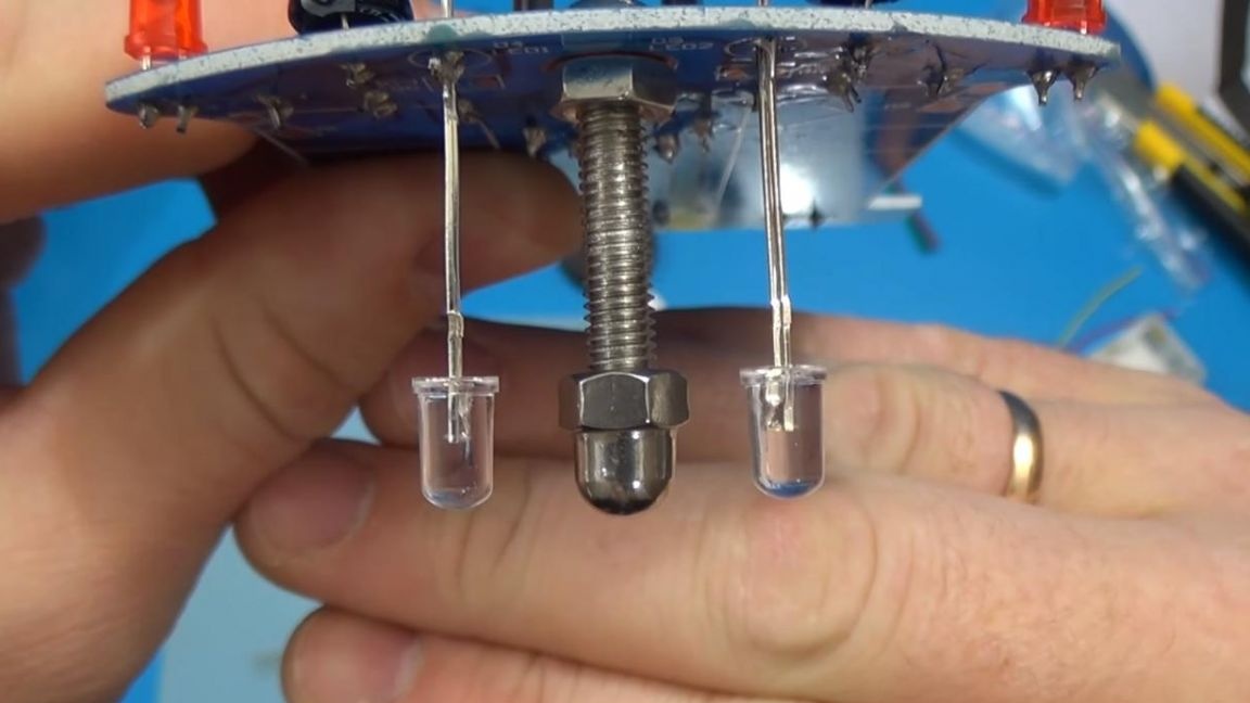
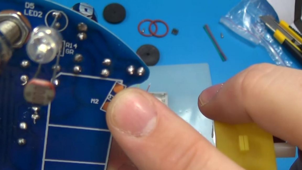
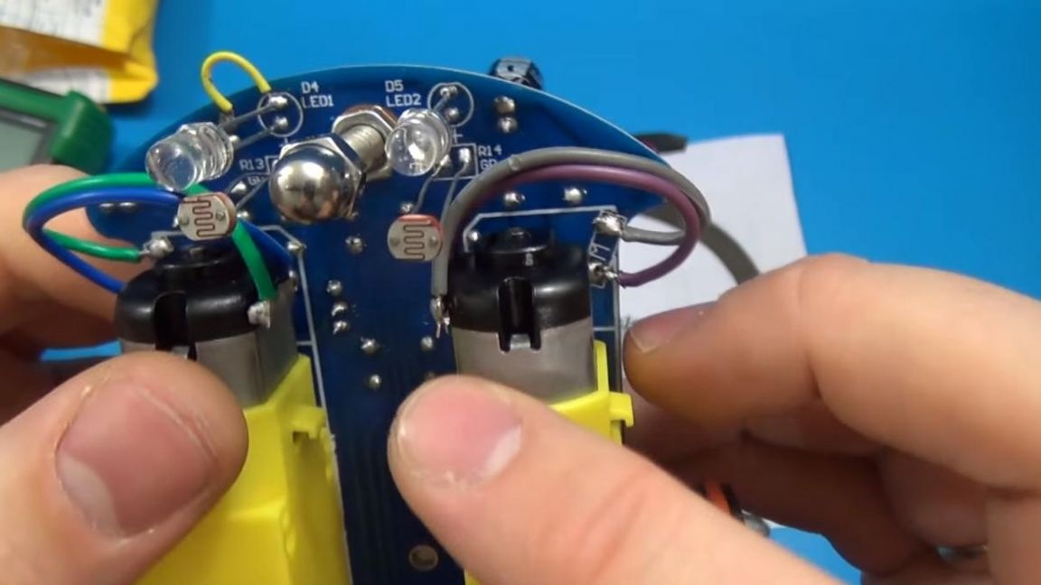
Now we fasten the screw to the board and install white LEDs next to it, their distance should be 1-2 mm less than the screw extension, this can be clearly seen in the photo, if this is not observed, then the photoresistors will work worse or not work at all .
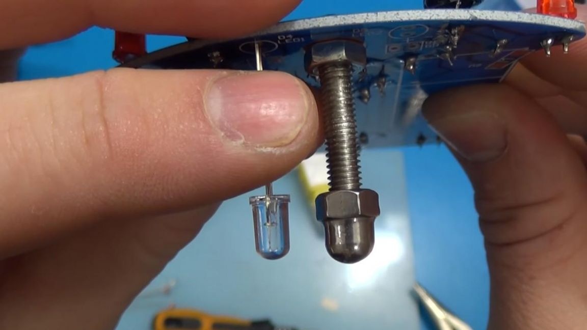
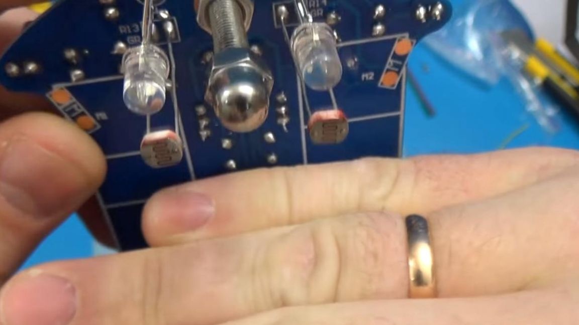
Next to the board, solder the photoresistors at the same distance as the LEDs.
Step Six
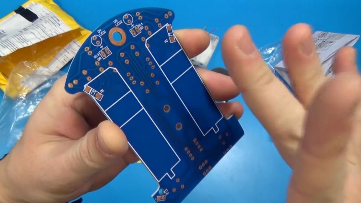
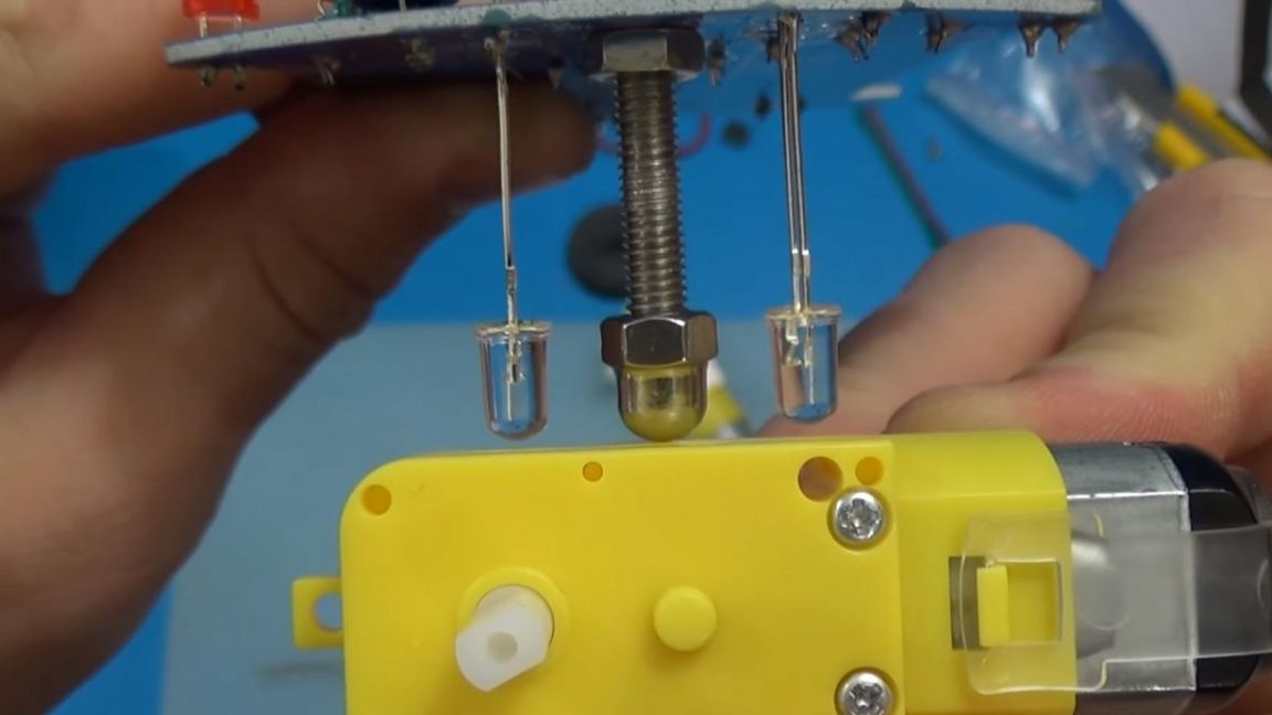
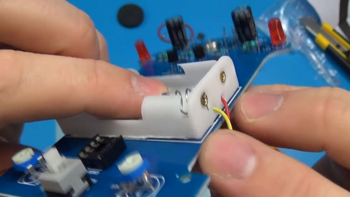
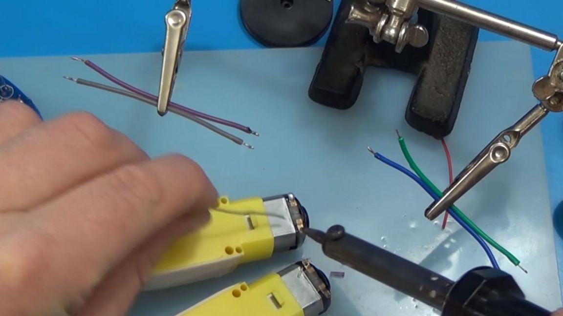
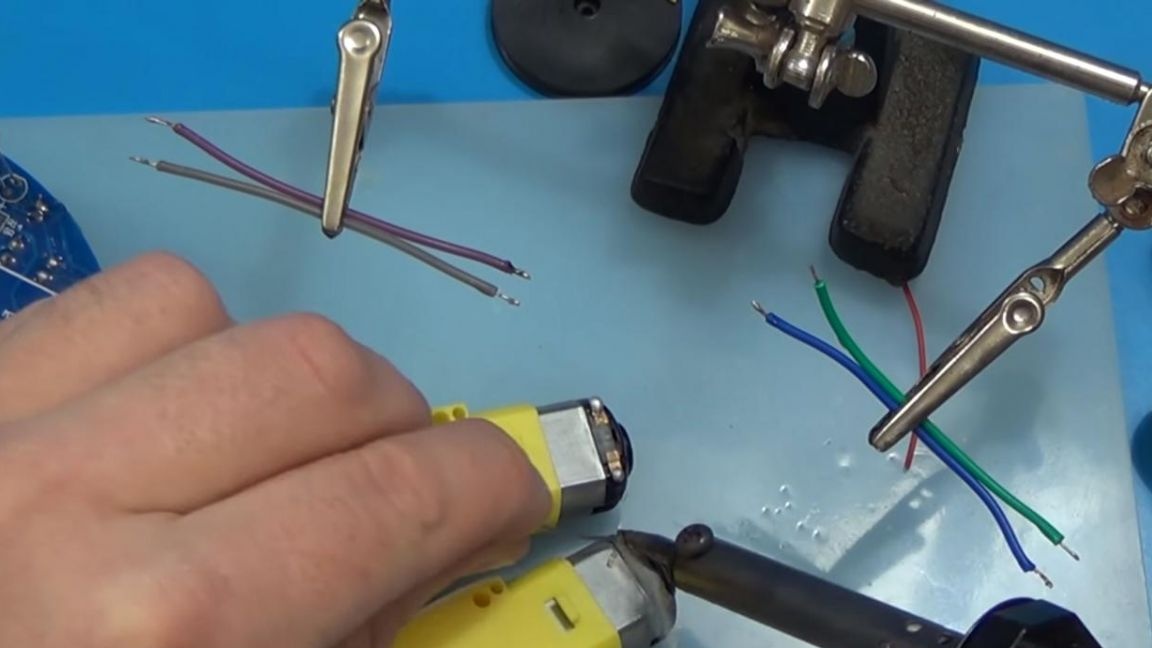
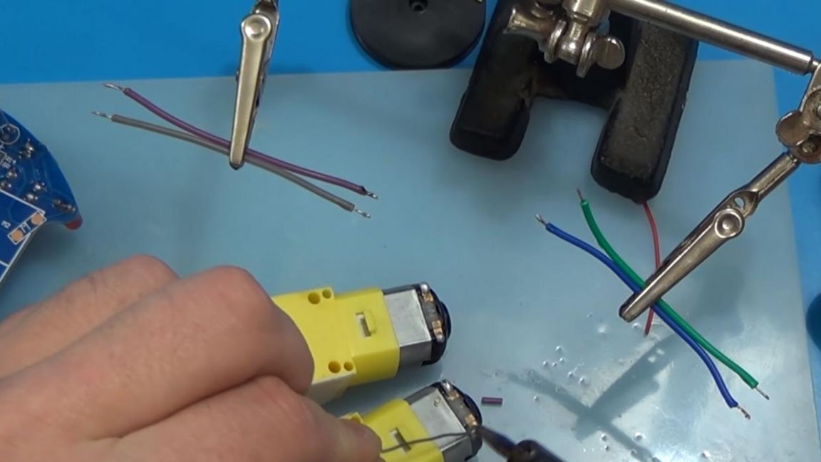
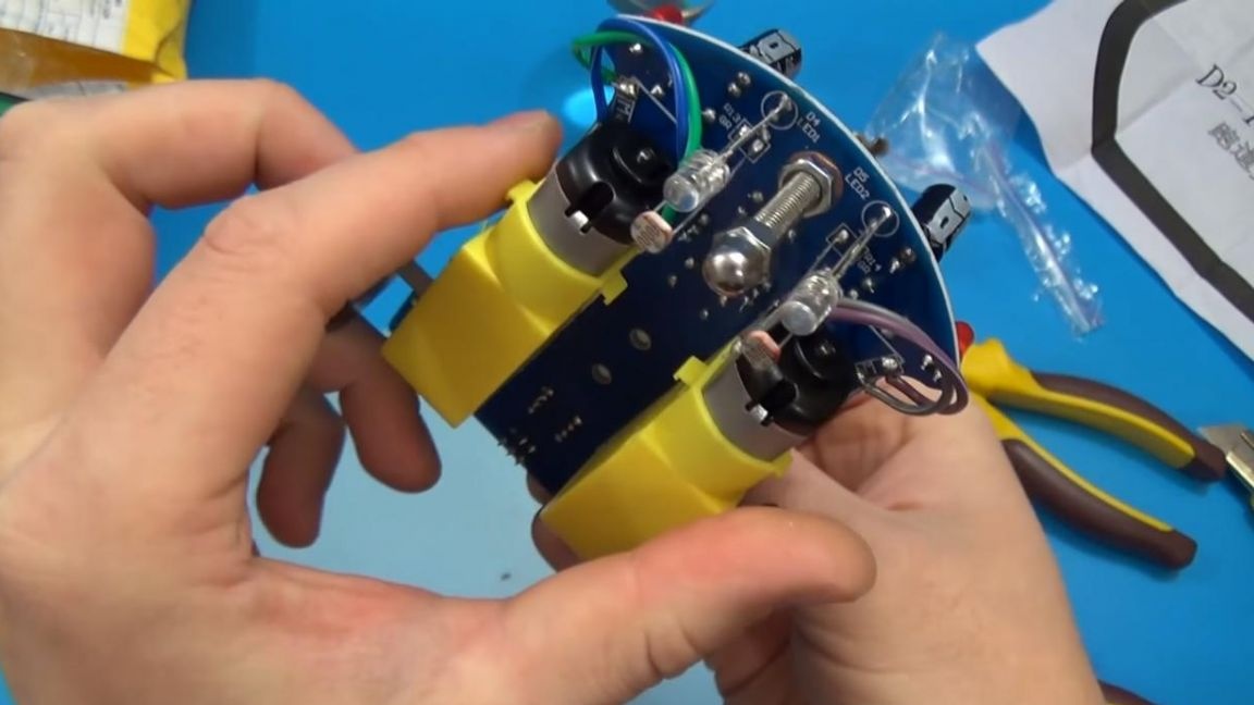
Then we take motors with gears, their contacts need to be tinned and two wires soldered to them, we also glue the case for installing AAA batteries and solder the yellow wire to the minus and the red wire to the plus, since it is signed on the board.
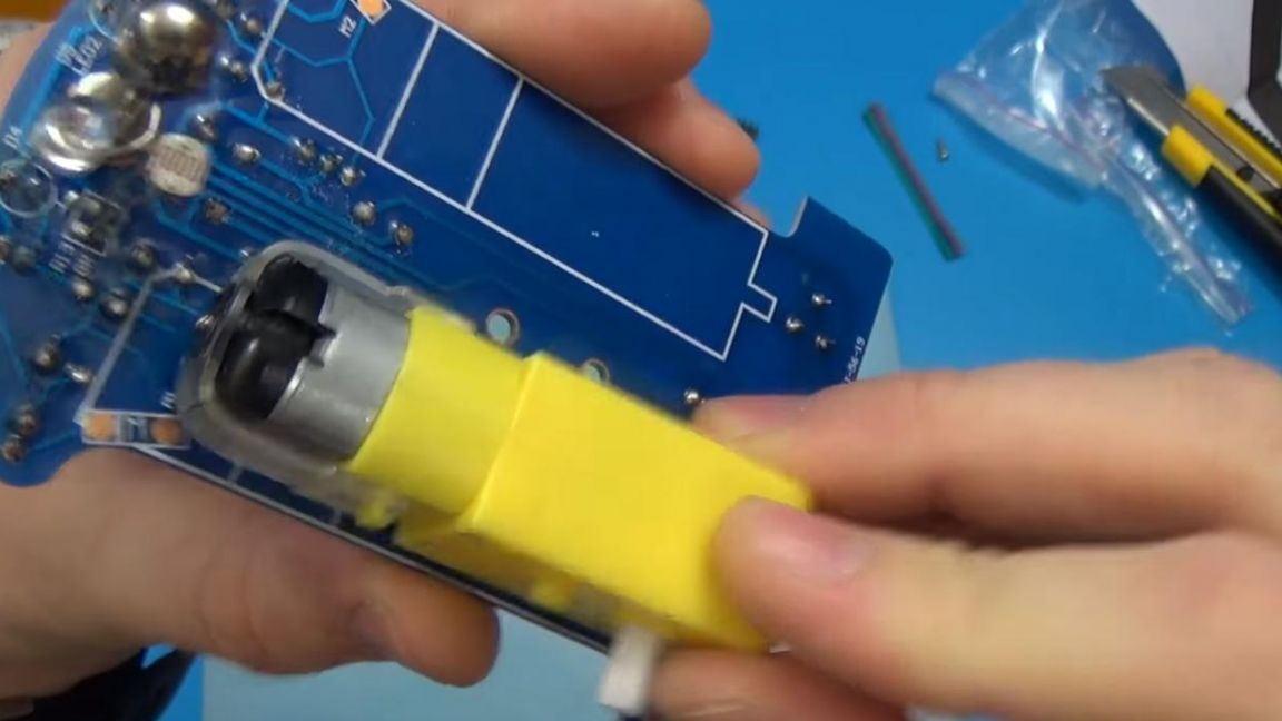
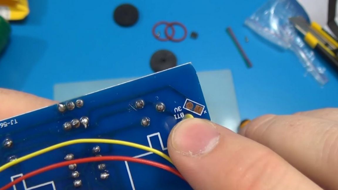
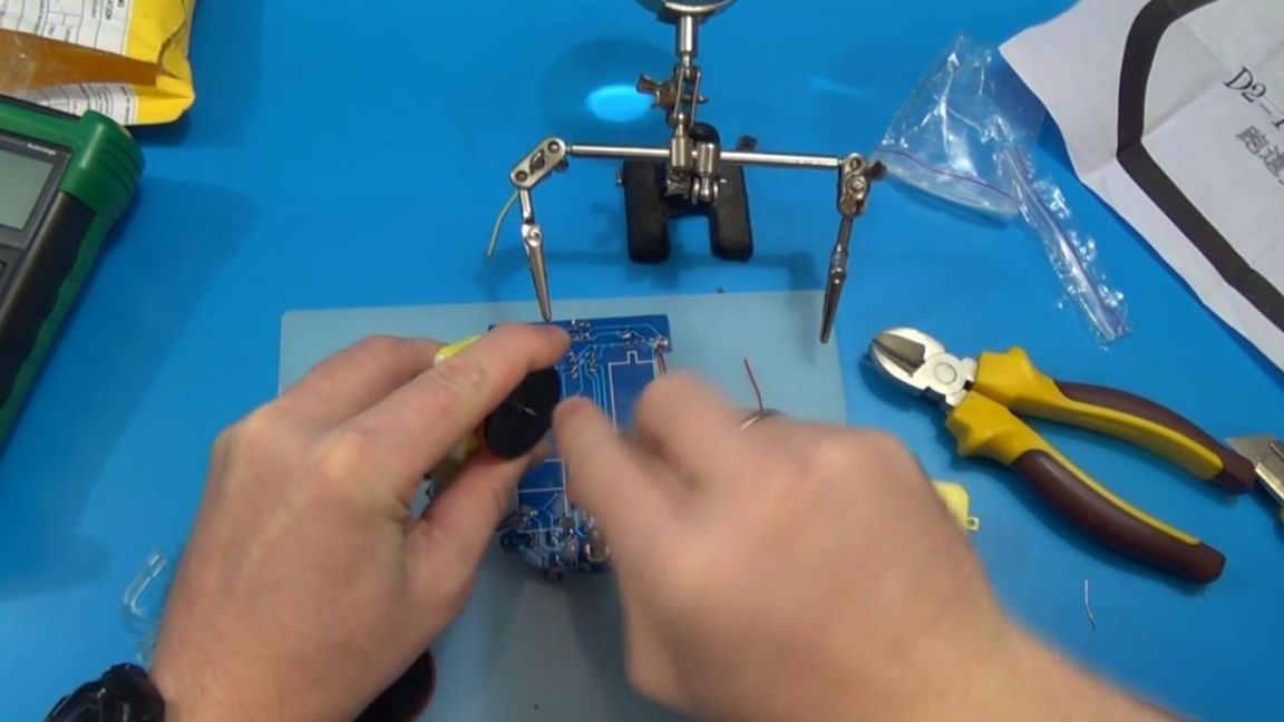
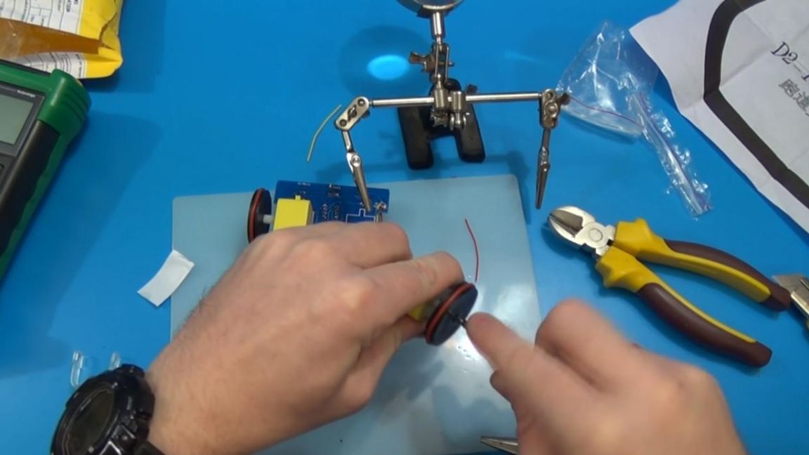
Before you attach the motors you need to fasten the wheels to them, which are fastened with one bolt, and a rubber pad is put on the wheel itself for better grip.
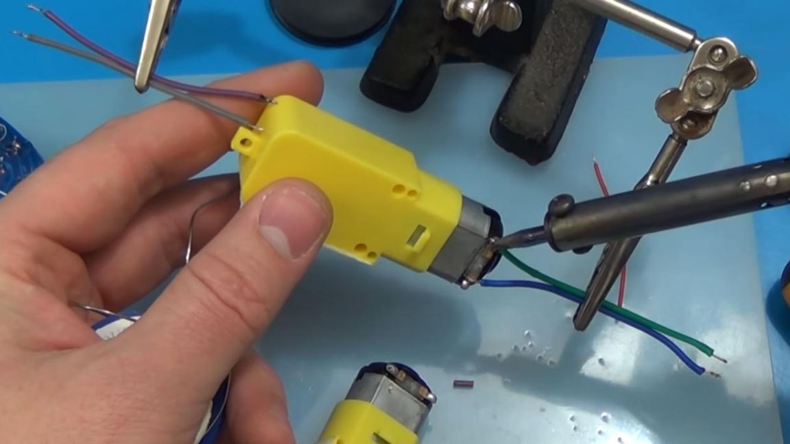
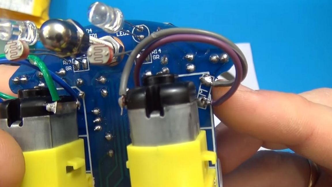
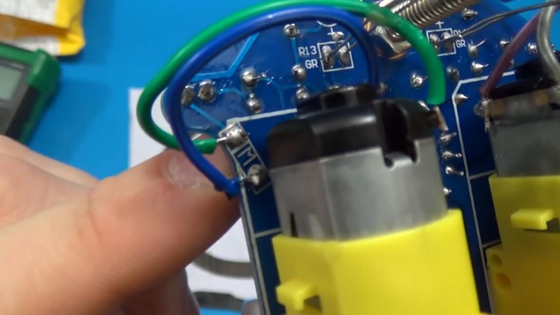
We solder the wires from the motors to the board, unfortunately where is the plus, and where the minus is not indicated here, but by trial and error it was found that the top contact of the motor must be connected to the top on the board using a wire and a soldering iron, with the bottom, respectively, we do the same .
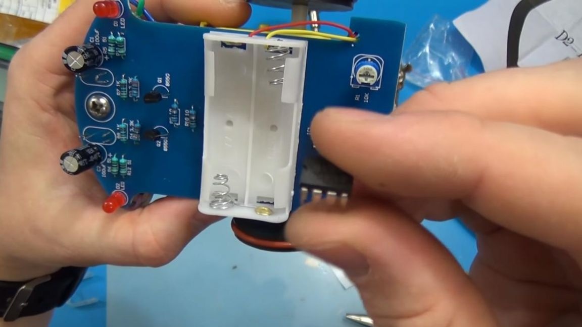
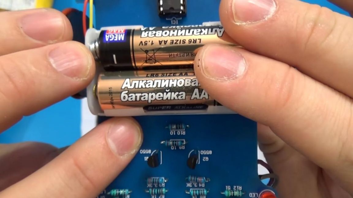
Well, at the end of the assembly, it remains to install the chip on the board in its rightful place, combine the key with the board and insert the batteries, observing the polarity.
Seventh step.
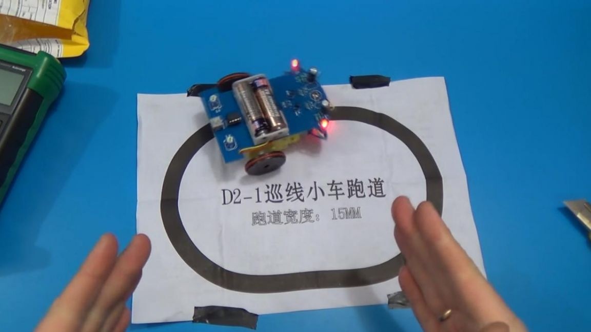
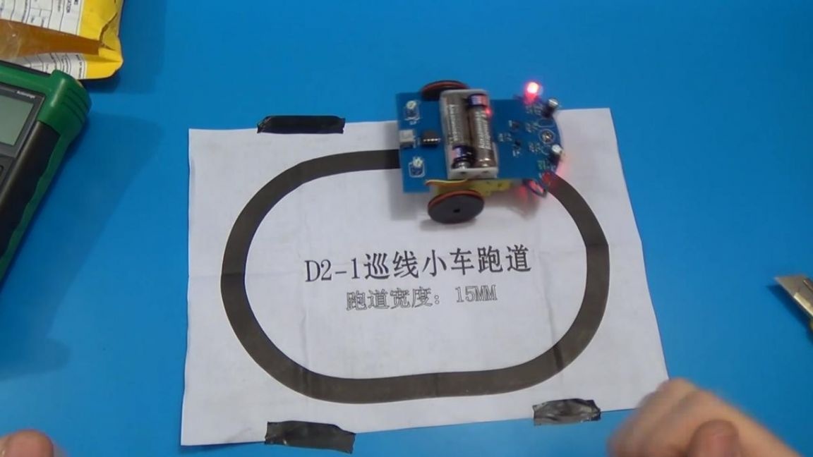
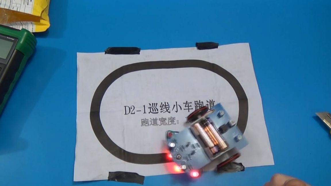
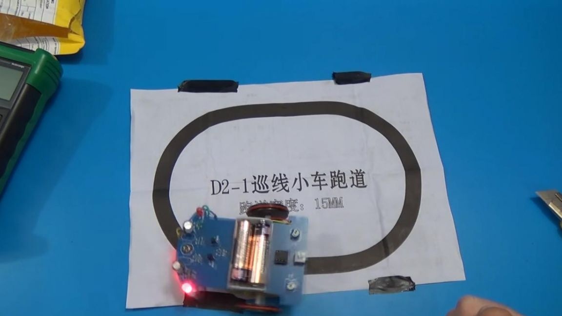
So the time has come to test this robot, the kit included instructions on the back of which an oval was drawn with a line with a width of 15 mm, which is the optimal value.
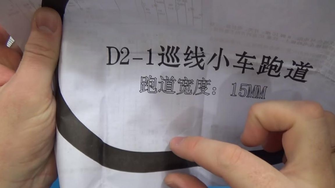
Press the power button and robot I went, for his proper operation, the lines should not be sharp, that is, he will not be able to make sharp turns. For example, you can make a track with smooth turns by applying an insulating tape with a width of 15 mm onto an even coating.
That's all for me, thank you all for your attention and creative success.