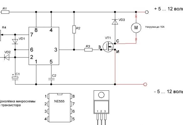
To begin, consider the scheme that we have to collect. This is a PWM controller circuit on a very common NE555 chip.
Regulator circuit
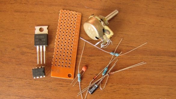
Nothing complicated and the details are the most common and cheap, especially if you buy them in China. Prepare the components.
We will need:
R1 and R2 resistors of 1 kΩ, R3 - 100 ohms,
R4 potentiometer 4.7 Kom,
C1 capacitor 1 Mkf 25 volts, C2 - 10n,
VD1, VD2, VD3 - diodes for example 1N4148 or any similar,
VT1 is an IRF630 transistor or the like,
NE555 chip or equivalent,
transformer 220 volts to 12 volts.
Select the power of the transformer based on your desire, what kind of load you will give it. The IRF630 transistor allows you to adjust the power to 10 amperes, if you need more, then choose another from this series. Depending on the planned load, you need to use the wires, which are marked in red on the diagram.
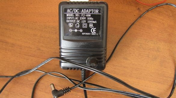
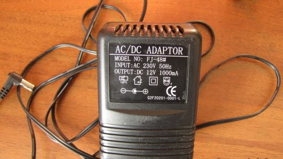
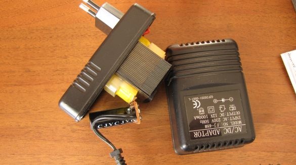
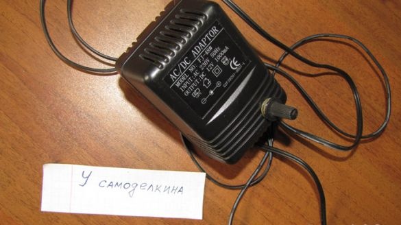
The power supply, which we will remodel.
I will connect one or two fans to the power supply unit and a power of 1000 mA is enough for me.
We disassemble the block.
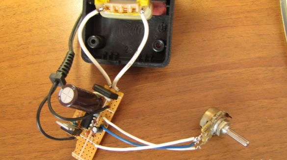
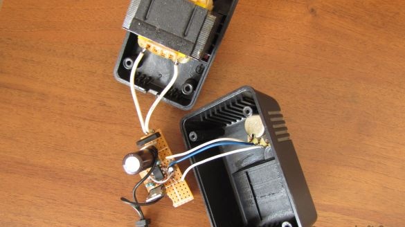
As you can see in the photo, it consists of a 220 volt to 12 volt transformer, a rectifier bridge with four diodes and a smoothing capacitor. We solder the rectifier block - we do not need it. We put our rectifier unit, together with the regulator, on one board.
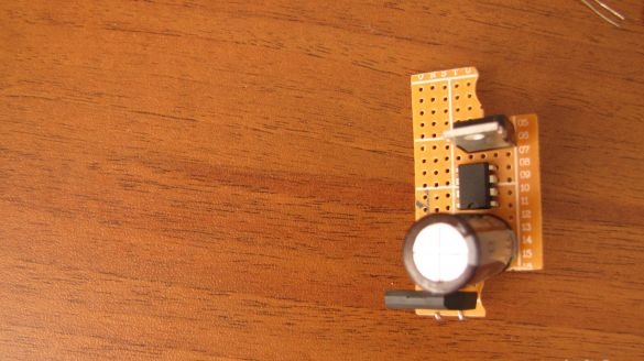
We will assemble the device on a circuit board (it’s more convenient and you don’t have to bother with making a printed circuit board, moreover, it’s very easy to fit it to the right size, just scratch it with an office knife and break it off). Fit the board to insert it into the power supply housing and you need to do it first.
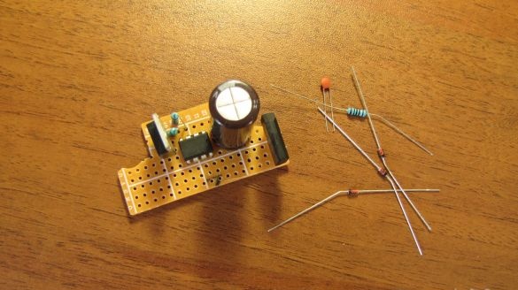
We install the parts on the board, in accordance with the scheme, starting with the largest elements. This is a capacitor and potentiometer. We place them in the case and try to close the top cover, if anything does not interfere, then they will stand in the finished product. Solder with any flux and tin.
Next, install the following parts and solder them. And so, in turn, checking the scheme.
It is better to solder each part in turn, immediately after installation and reconciliation with the circuit.
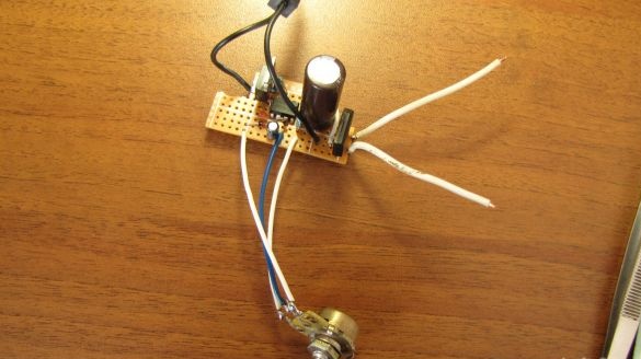
During the assembly process, constantly check the diagram and everything will work well. The circuit does not need to be configured, and with serviceable parts and proper installation without errors, it starts working immediately after turning on the power.
A cooler connected to such a power supply changes revolutions from zero to maximum very smoothly with excellent linearity.
Good luck with your business.


