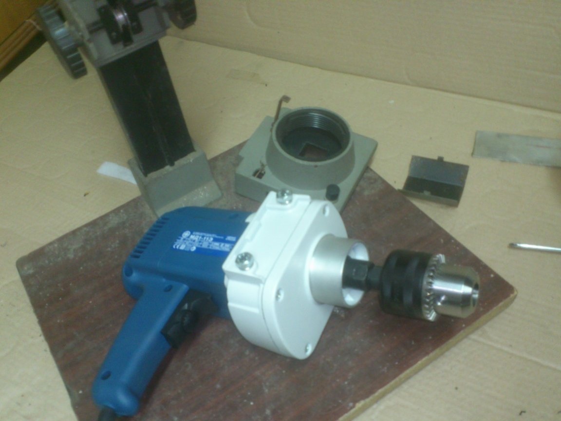
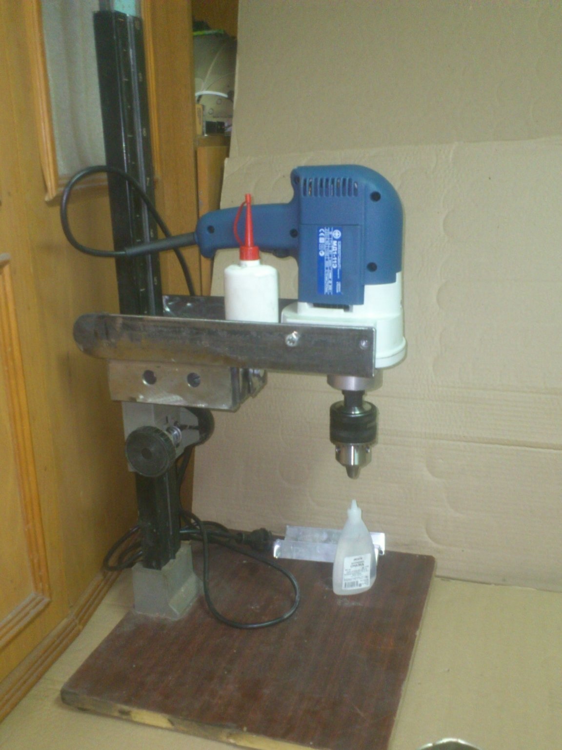
I have long wanted to make myself a drilling machine. It is a drilling machine, not a rack for an electric drill! There is a significant difference between these similar devices - the stand only provides the vertical, and the drilling machine, having high power and significant torque at low speeds, allows you to drill holes of sufficiently large diameters in thick metal (which a drill cannot do). That is why, as a power unit, I decided to use the Fiolent-MD1-11E drill mixer. Since I am going to make a vibrating table in the near future and start making paving slabs, I studied the characteristics of construction mixers, because I need such a power tool for this .. This model attracted my attention with its characteristics:
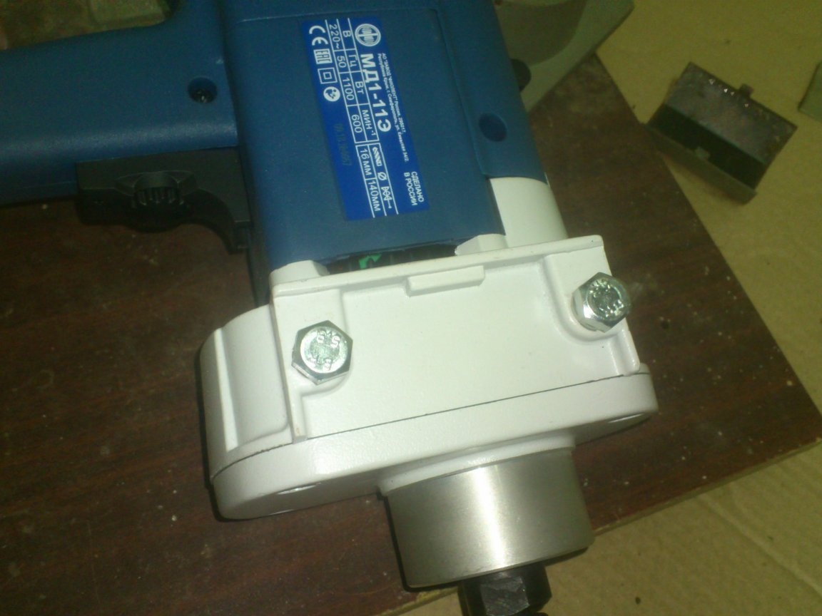
Power 1 100 W
Spindle speed (maximum) 600 rpm
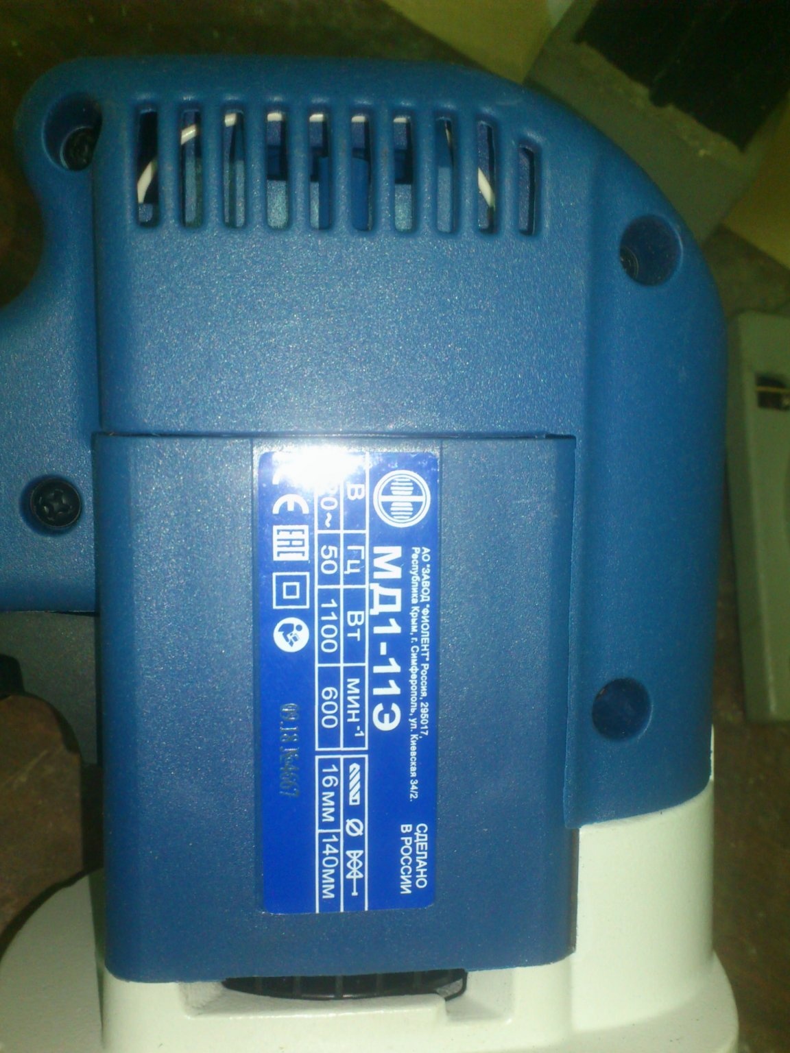
In addition, judging by the numerous reviews of the owners, this model has exceptional reliability.
And when I got such a mixer, I had the idea of “kill two birds with one stone” - to make a drilling machine out of it too! )))).
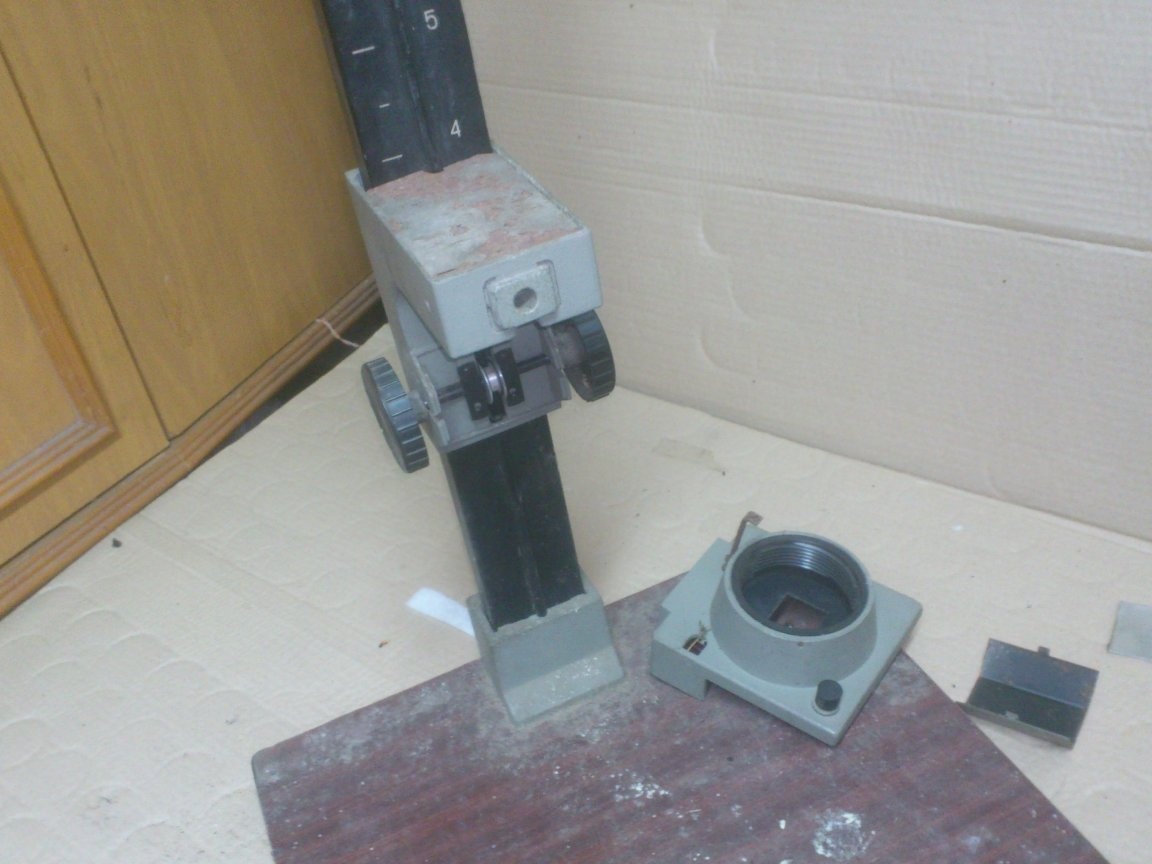
The idea of using a photo enlarger, as an almost ready frame of the future drilling machine, suggested to me article on this site, which the author posted under the nickname PORUCHIK. Moreover, the exact same photo enlarger was also in my youth, and was preserved in my brother's attic.
Here in such deplorable form he returned to me:
So here is what I needed:
1. Photographic enlarger "Tavria".
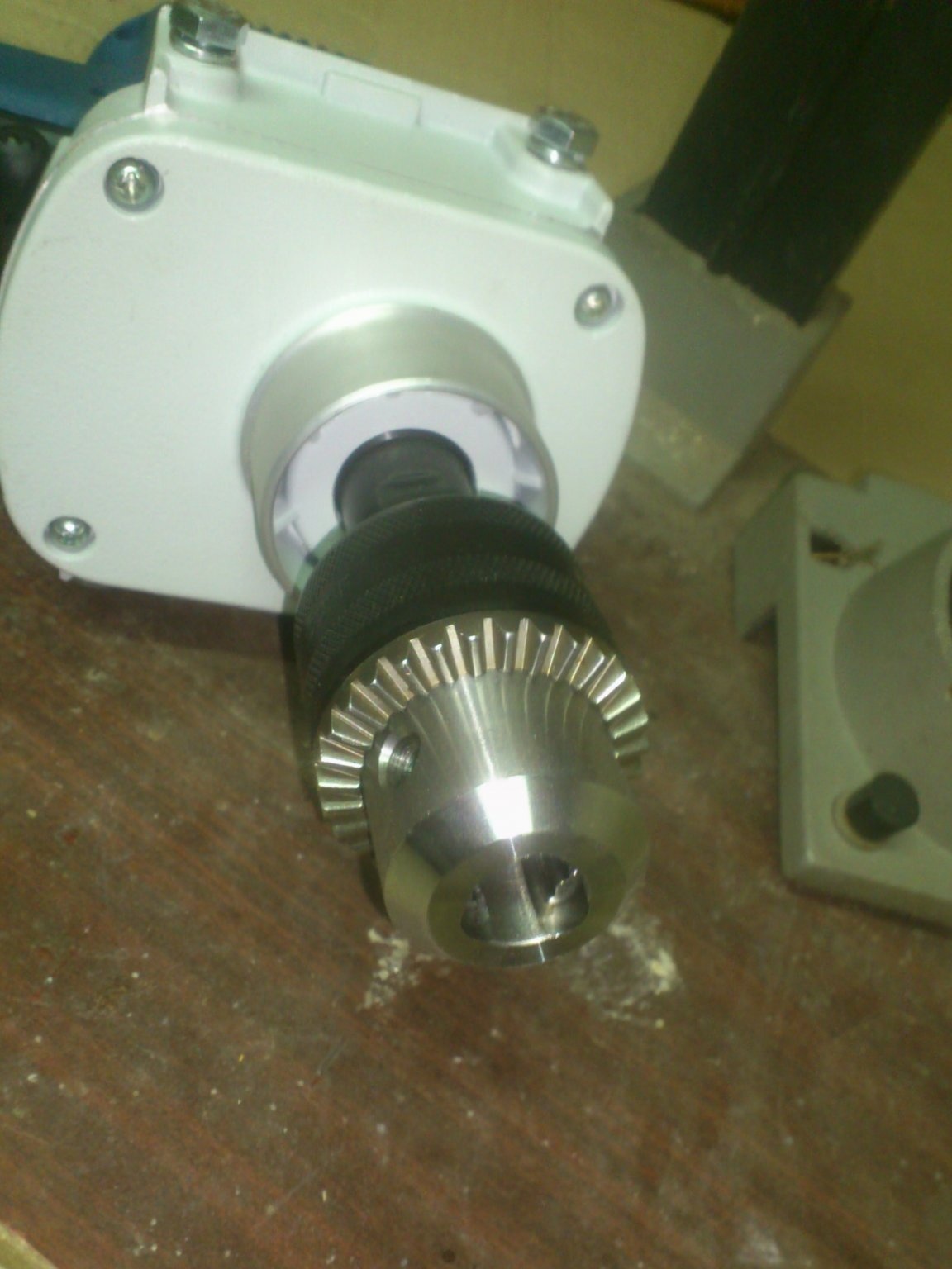
2. Drill-mixer "Fiolent"
3. Stud adapter and drill chuck 16 mm.
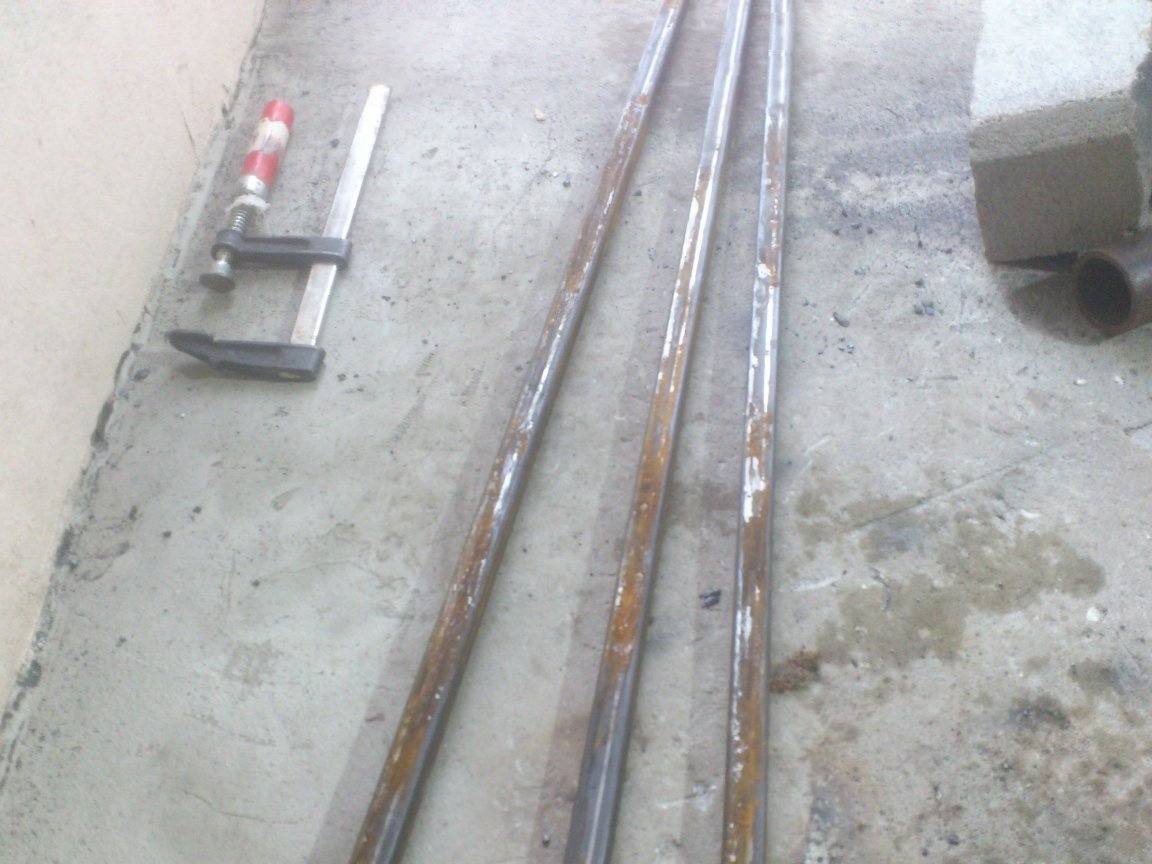
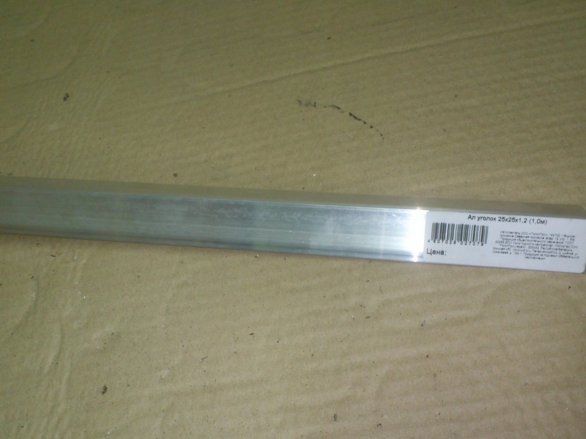
4. Cutting of profile pipes with a cross section of 50 by 20, 50 by 50, 15 by 15 millimeters.
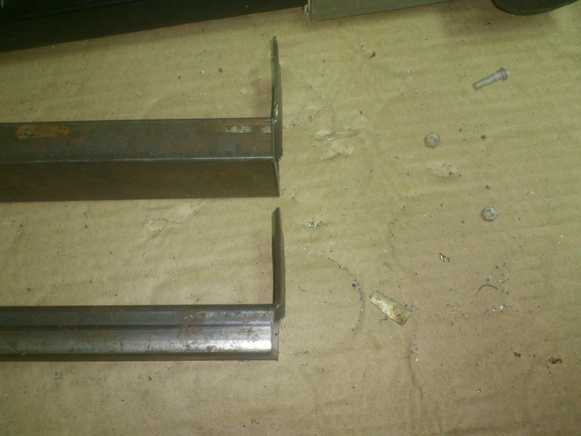
5. Trim angle 50-50-5.
6. Trimming the construction stud M16.
7. Circle 8mm.
8. A piece of laminated plywood 20 mm thick
9. Trim pipe DN 32.
10. Scrap of roofing sheet.
11. Button BS542 "Fungus" emergency with fixing rotary.
12. Outlet single external layout.
13. diode floodlight 10 watts.
14. Steel cable, diameter 3 mm.
fifteen.Hardware of various types and sizes.
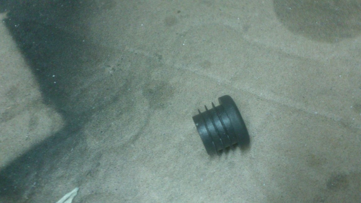
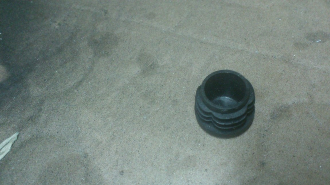
16. Plastic plugs for profile and plumbing pipes.
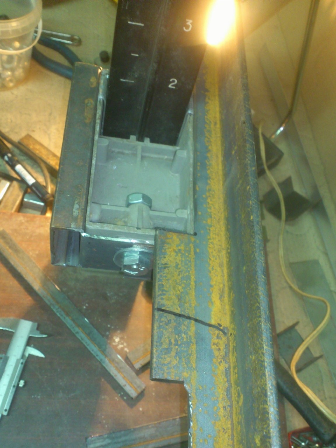
I began by designing the mounting of the mixer to the movable carriage. The mixer has a "seat" with which it is attached to the handle with four M8 bolts.
Having measured its width and the width of the photo enlarger carriage, I saw that the mixer was wider by 40 millimeters:
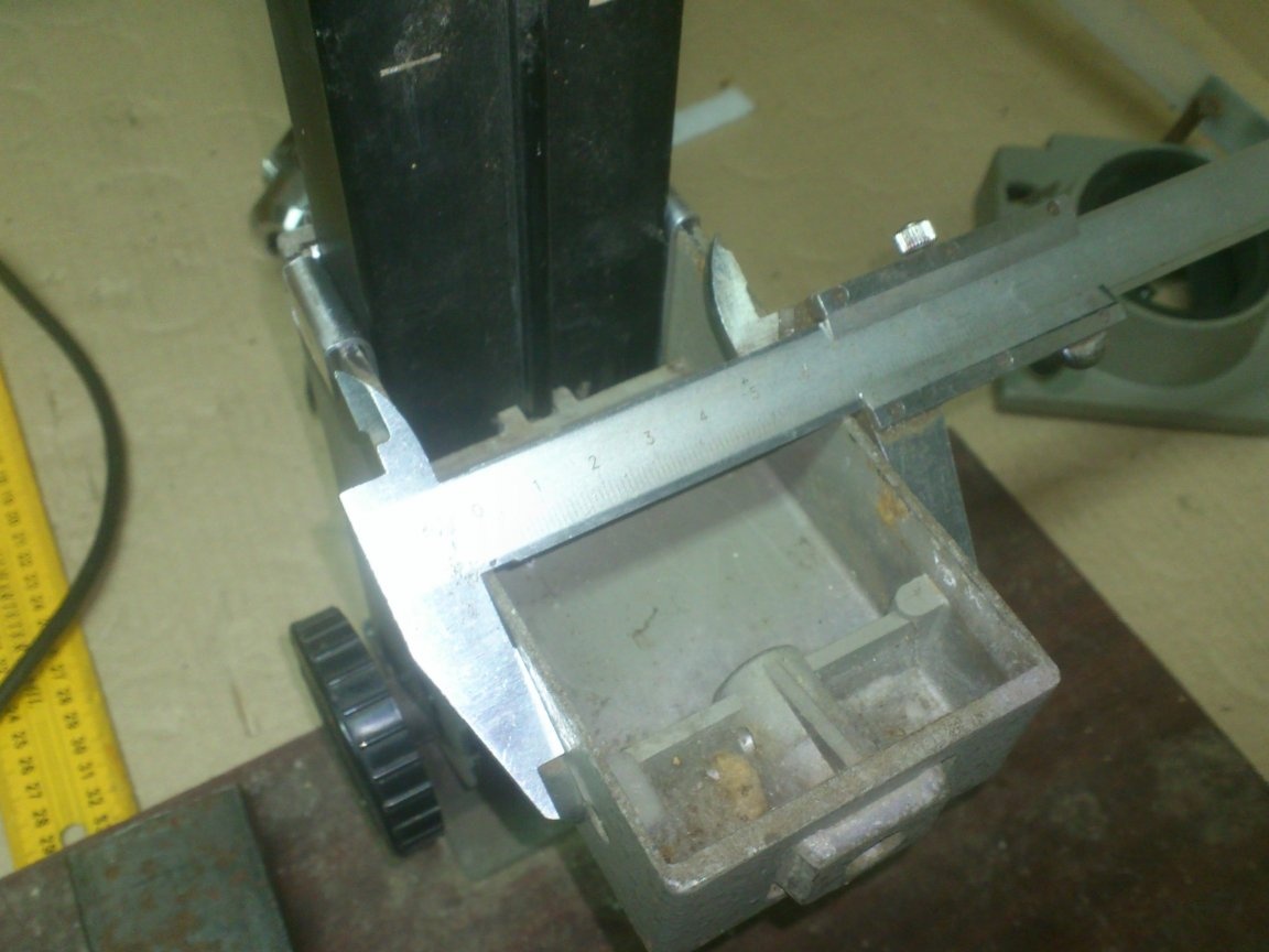
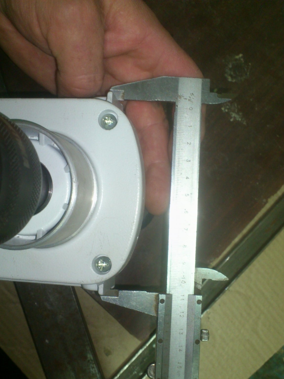
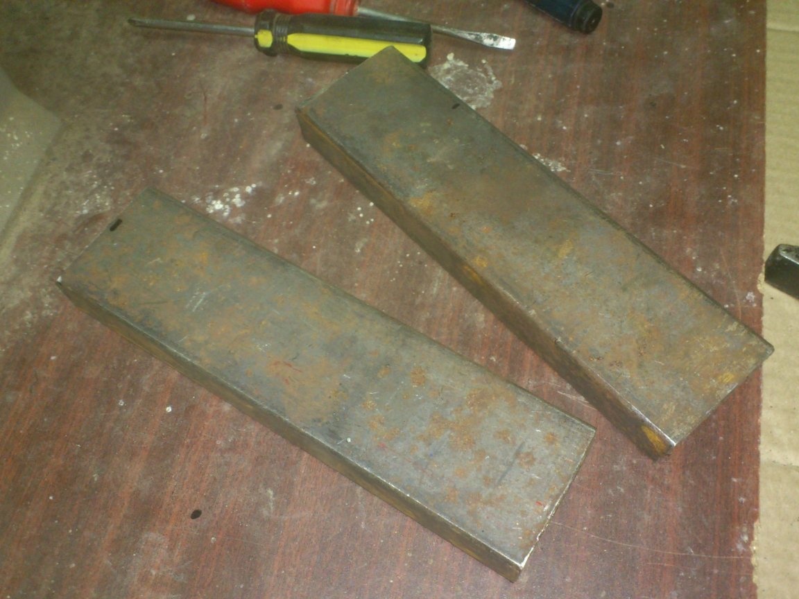
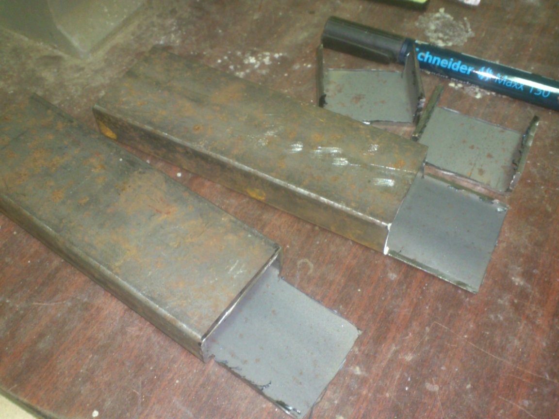
I decided to compensate for this difference by attaching on the sides of the carriage along a section of a profile pipe 20 by 50 mm section. (It was possible to use 20 to 40, and 20 to 30 ... but I only had 20 to 50 lying around. And my main rule: "Use first of all what lies around so that it does not disappear!")))))) .
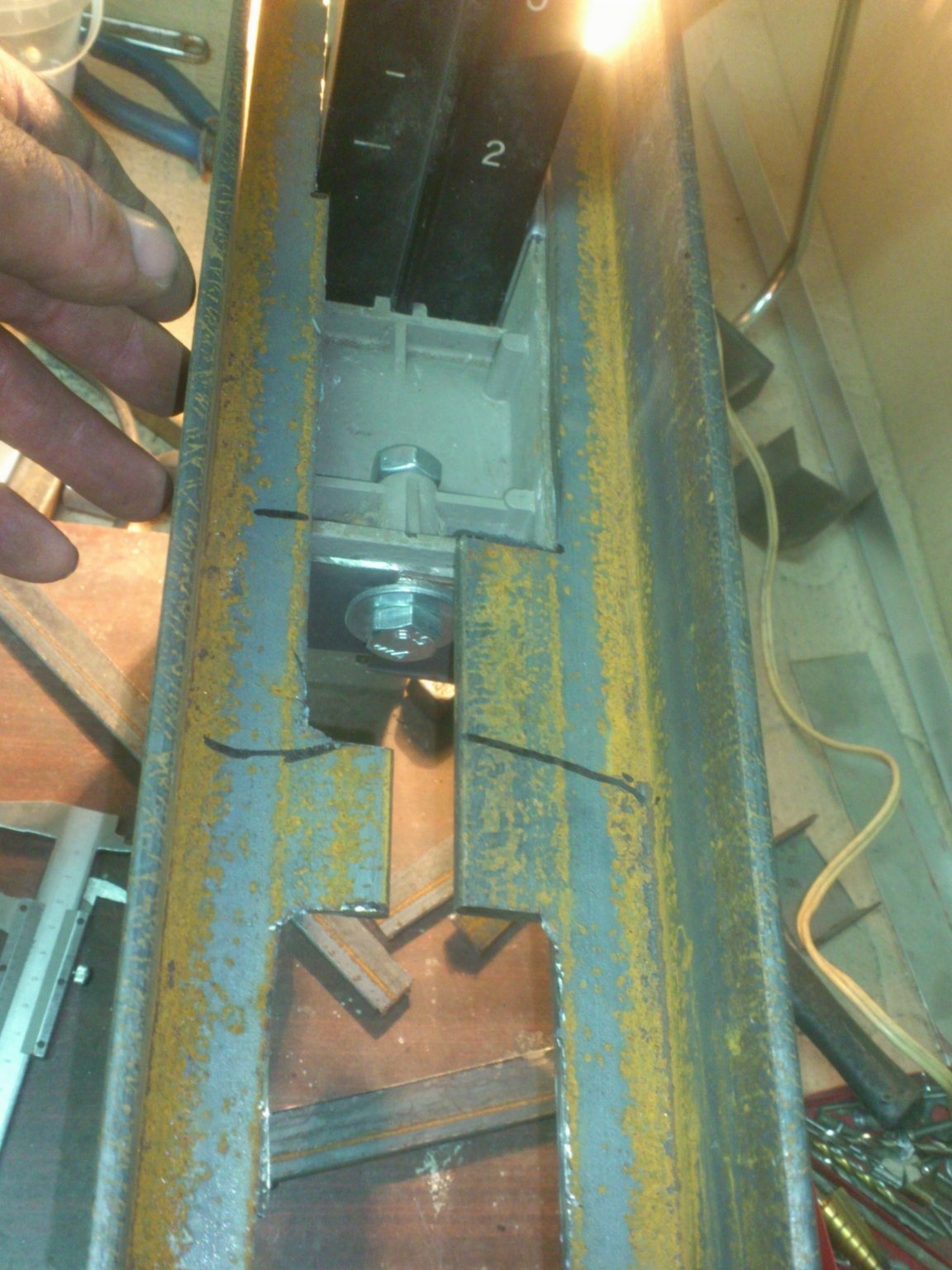
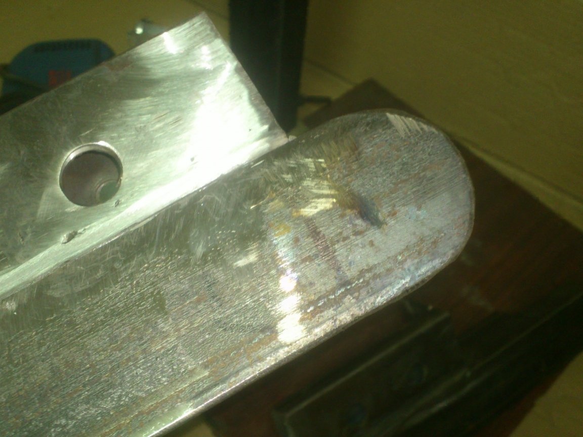
The carriage itself is made of aluminum in the form of a “box”. At the end there is a hole with a diameter of 10 mm. under the screw securing the head of the enlarger. I decided to fix the pads on the sides with M8 screws (for which two holes were drilled on each side), and bend the front and secure it with an additional M10 bolt with a nut:
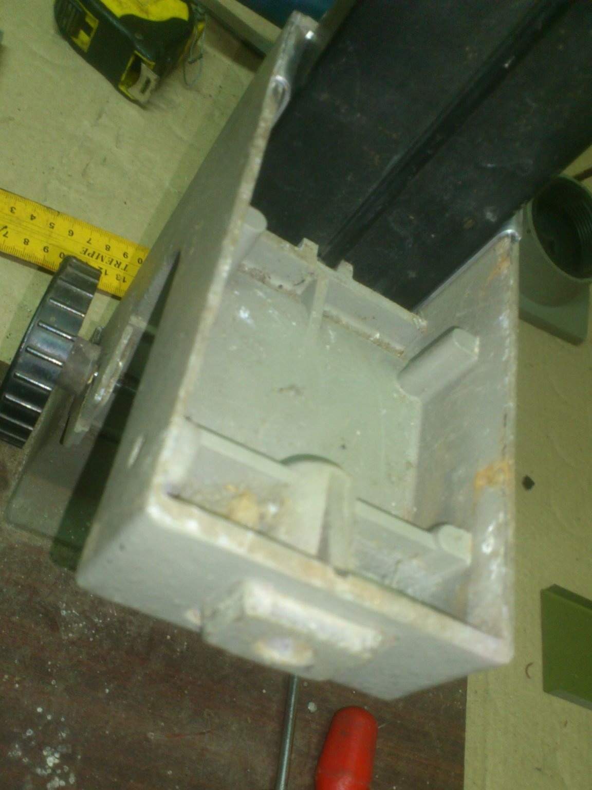
To prevent the pads from wrinkling with screws, I drilled the fixing holes in them with a conical drill - when an hole with a diameter of 8 mm was formed on the inner wall, it turned out to be 16 mm on the outer. A screw cap will pass through it, and holding it with a screwdriver, I will tighten the nuts inside the carriage. And then the holes for aesthetics will be closed with standard plastic plugs for the DN15 pipe - the diameter just coincides.)))
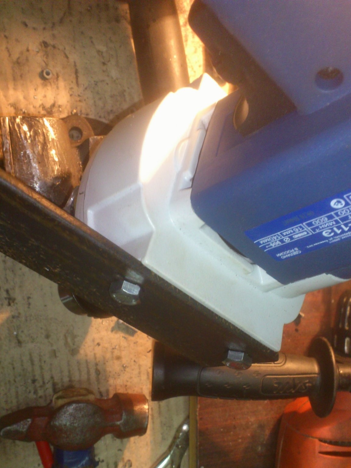
I decided to make a landing for the mixer from a steel angle of 50-50-5., Since the height of the side plane to the thrust side of the mixer is just 50 mm.
(In one cutout I made a little larger than necessary ... Well, God be with him!))))
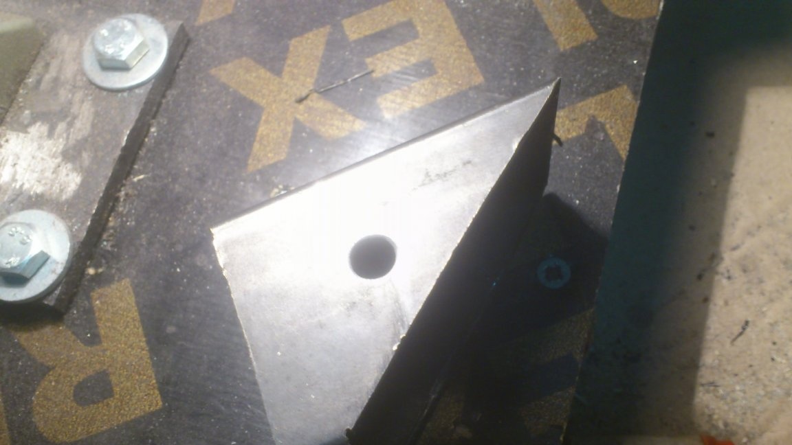
I drilled (very accurately) four holes for the screws, and secured the corners on the mixer with the “native” fixing screws:
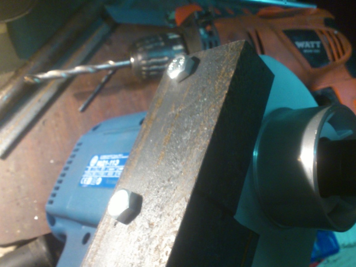
After that, I welded corners "landing" to the plates. (First, securing the corners on the mixer, and the lining on the carriage, put it together, pulled it together with clamps and “grabbed it.” Then he took it apart and boiled it well on both sides:
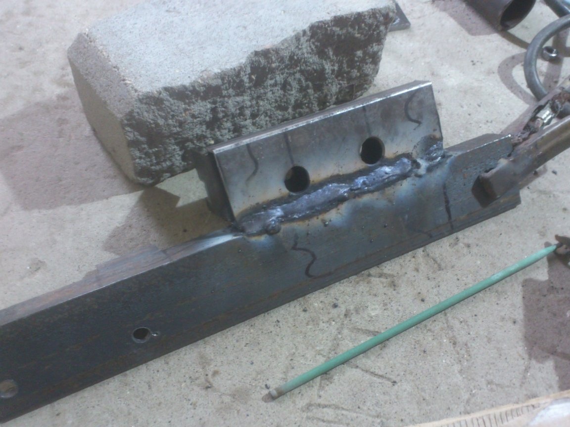
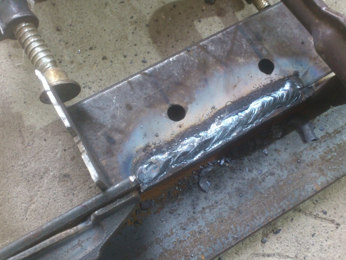
And cleaned (while roughly, in a clean circle)
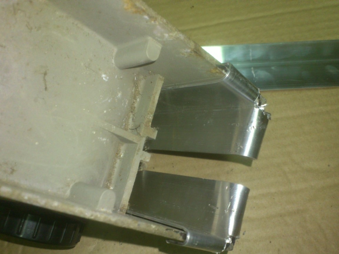
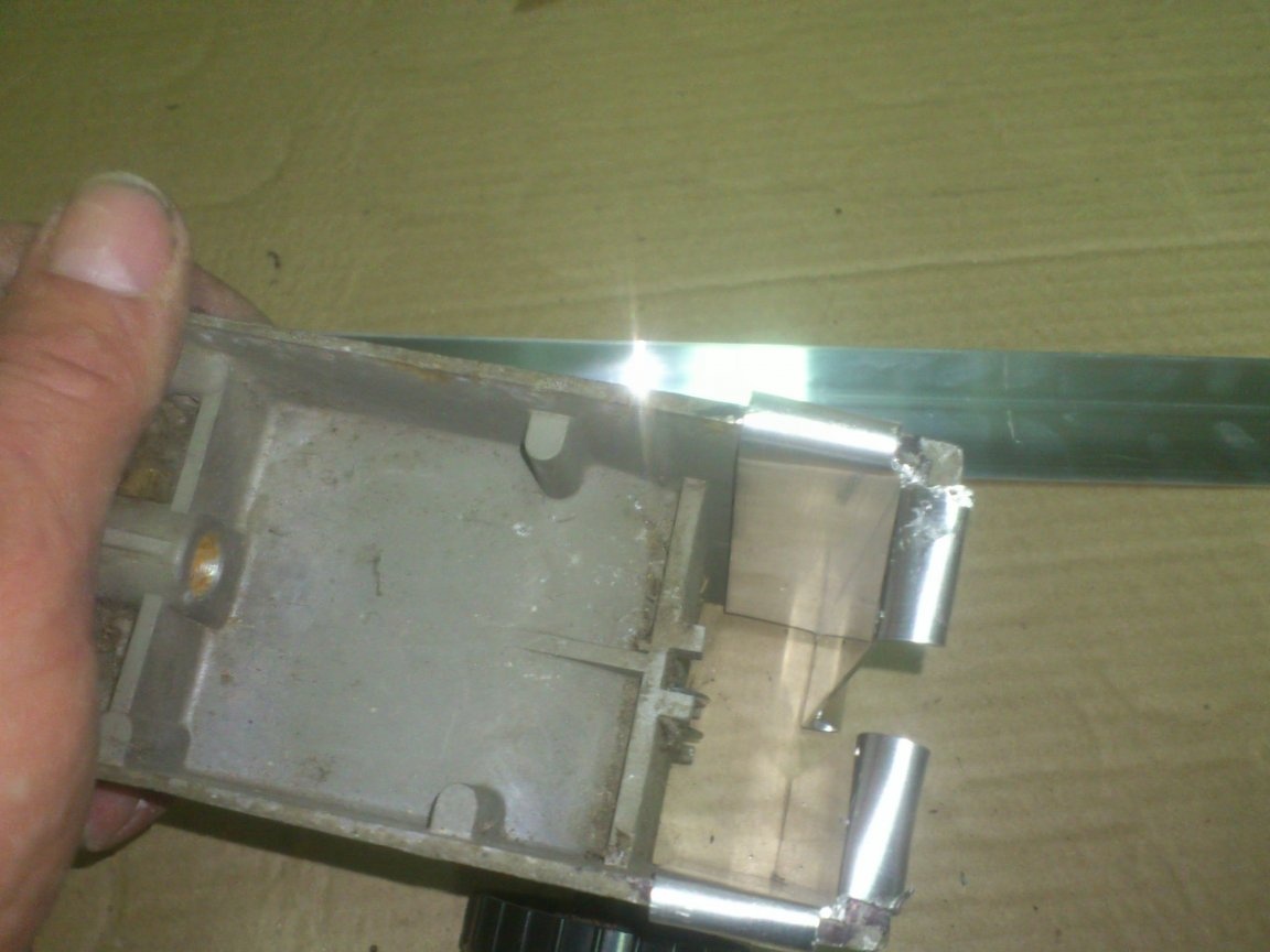
The roller lifting-lowering mechanism in the carriage was not suitable for my purposes. He is too weak:
 [
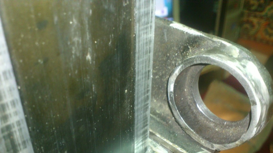
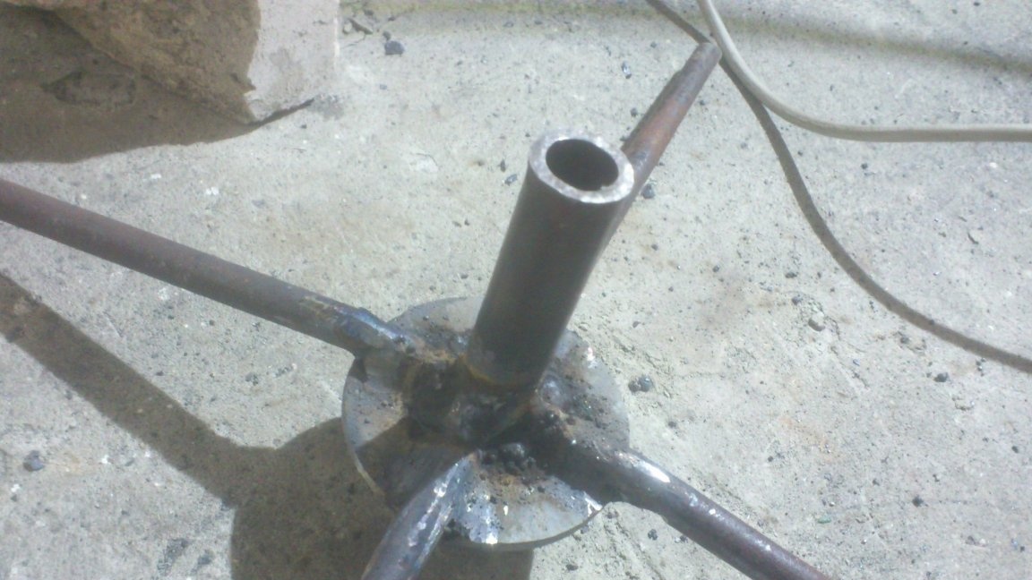
[Instead, I decided to make a more powerful cable mechanism. It will be located behind, behind the counter. And at this stage, I decided to make landing bearings. For this, I used trimming the water pipe DU32:
Having marked the required size with electrical tape, I cut two rings from the pipe:
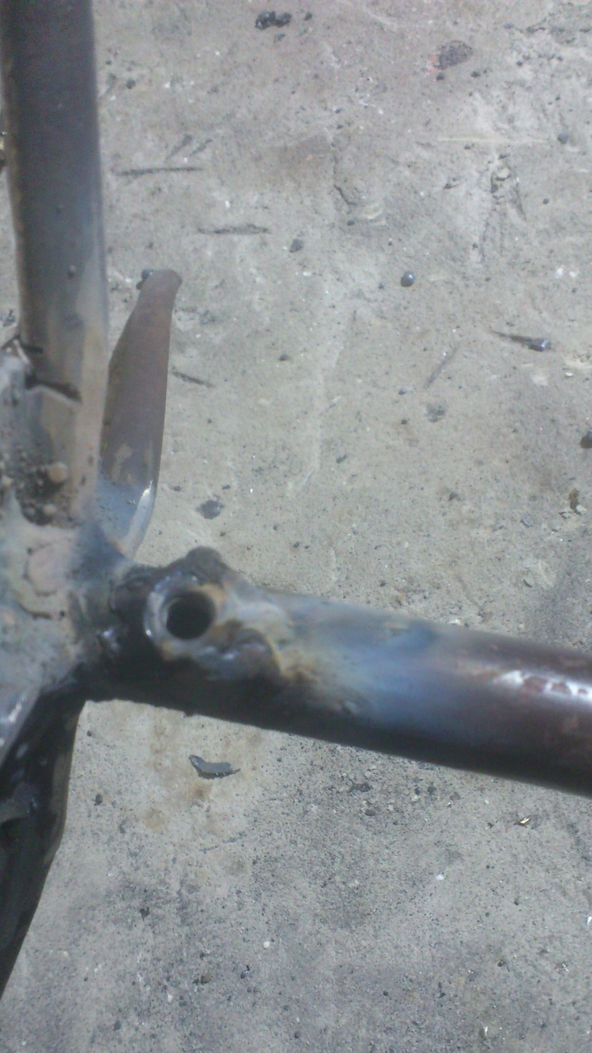
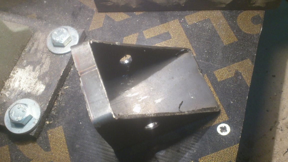
And I welded them to the parts of the corners protruding from behind the rack:
After which he cut off everything unnecessary and cleaned it up:
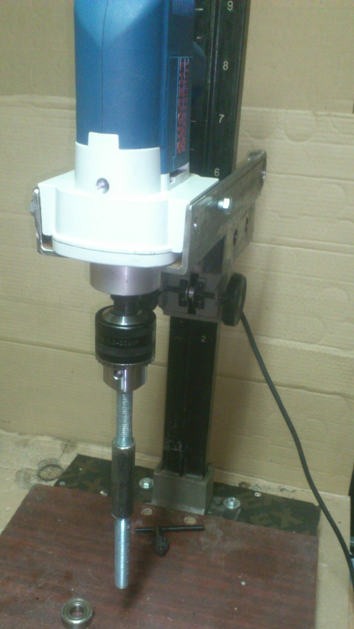
At this stage, you can already "try on"))))

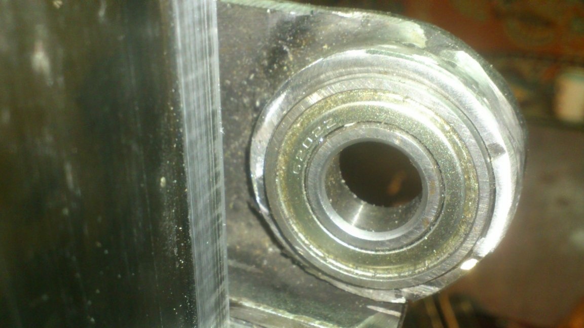
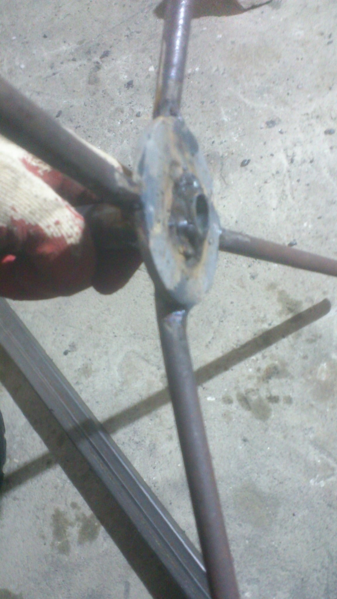
In the centers of the resulting landing, I drilled holes with a conic drill, 24 mm in diameter. (Ehhhh ... If I ALREADY had a machine tool! ... And so - with a drill! .... Can you imagine ?? ... My poor Chinese drill !!!)))))
They can now insert the 202nd bearings on which the shaft of the lifting mechanism will rotate:
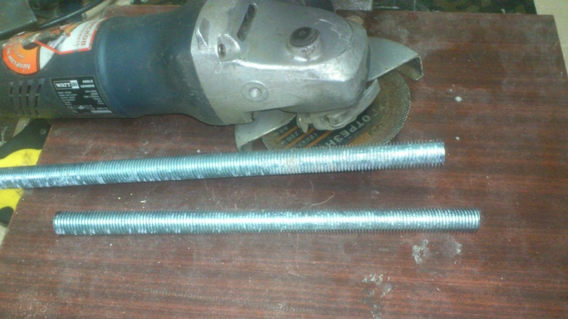
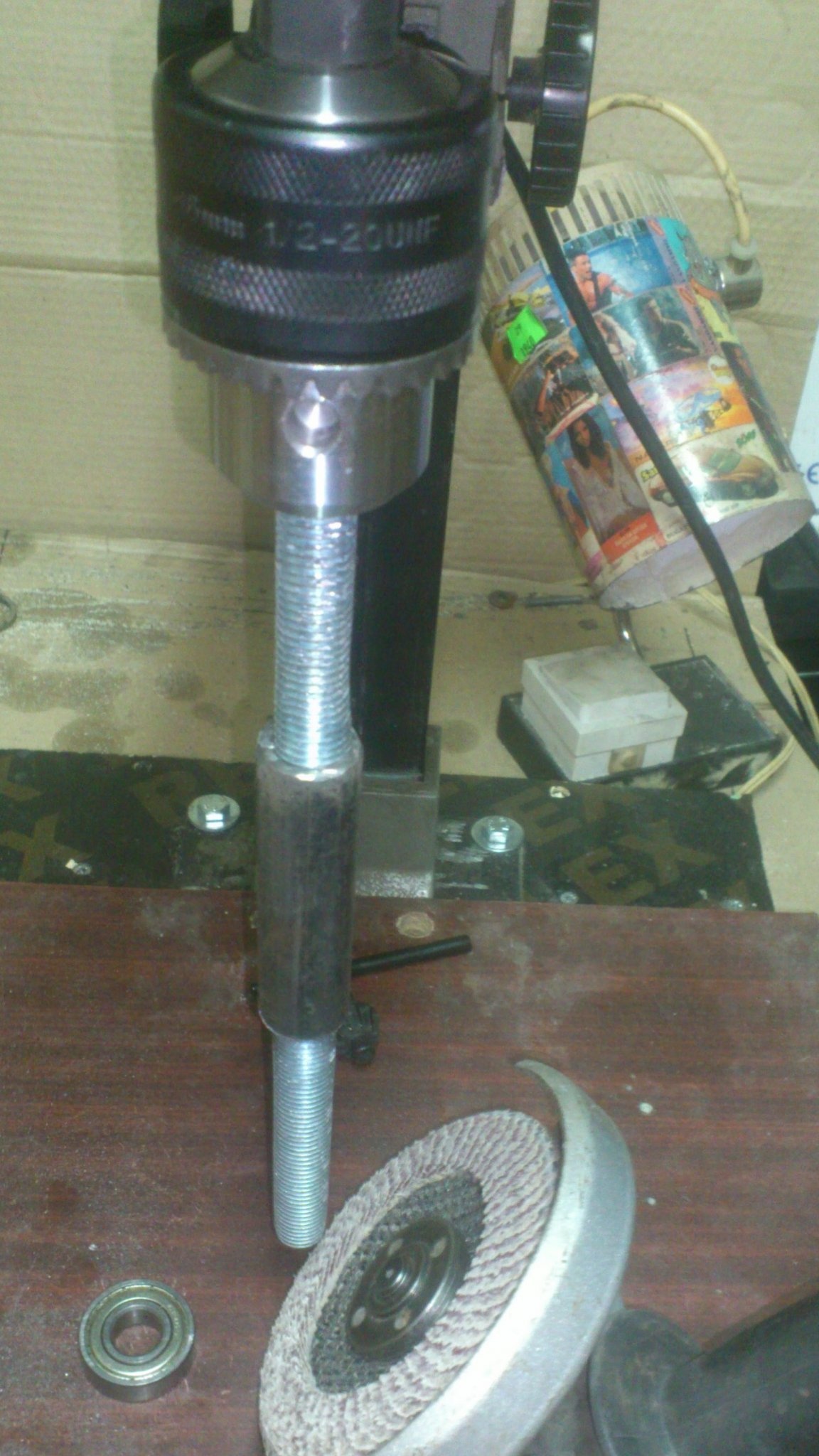
Now the shaft itself. I decided to make it from an M16 threaded rod, for which I cut off a piece of the length I needed with a grinder:
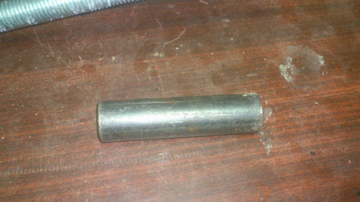
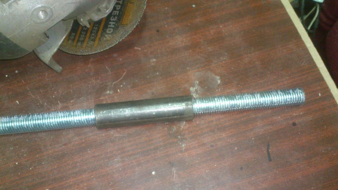
According to my idea, a piece of a water pipe ДУ15 will be dressed on a hairpin, which will act as a drum for winding the cable:
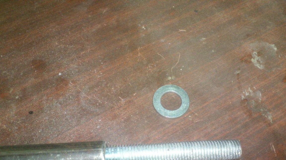
The function of the sides of the drum will be performed by two standard M16 washers:
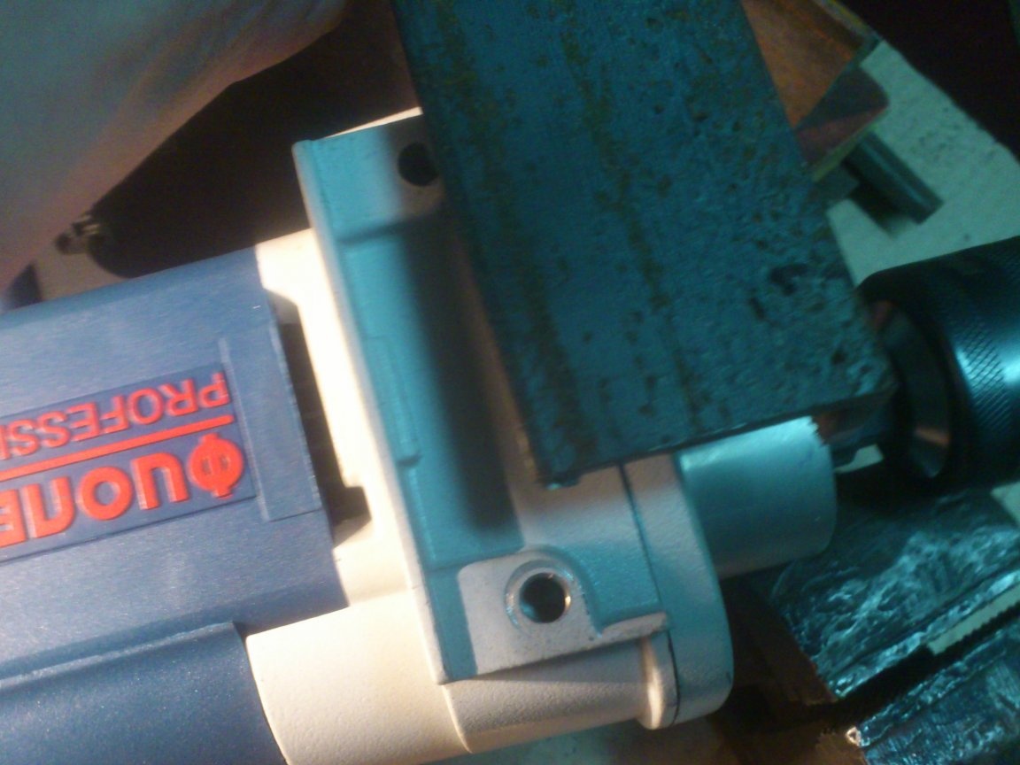
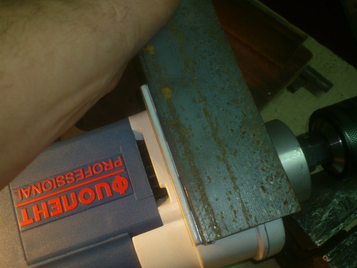
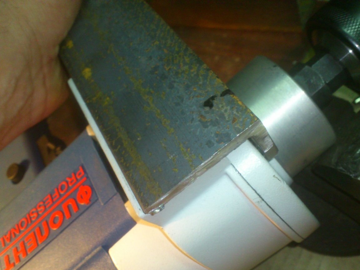
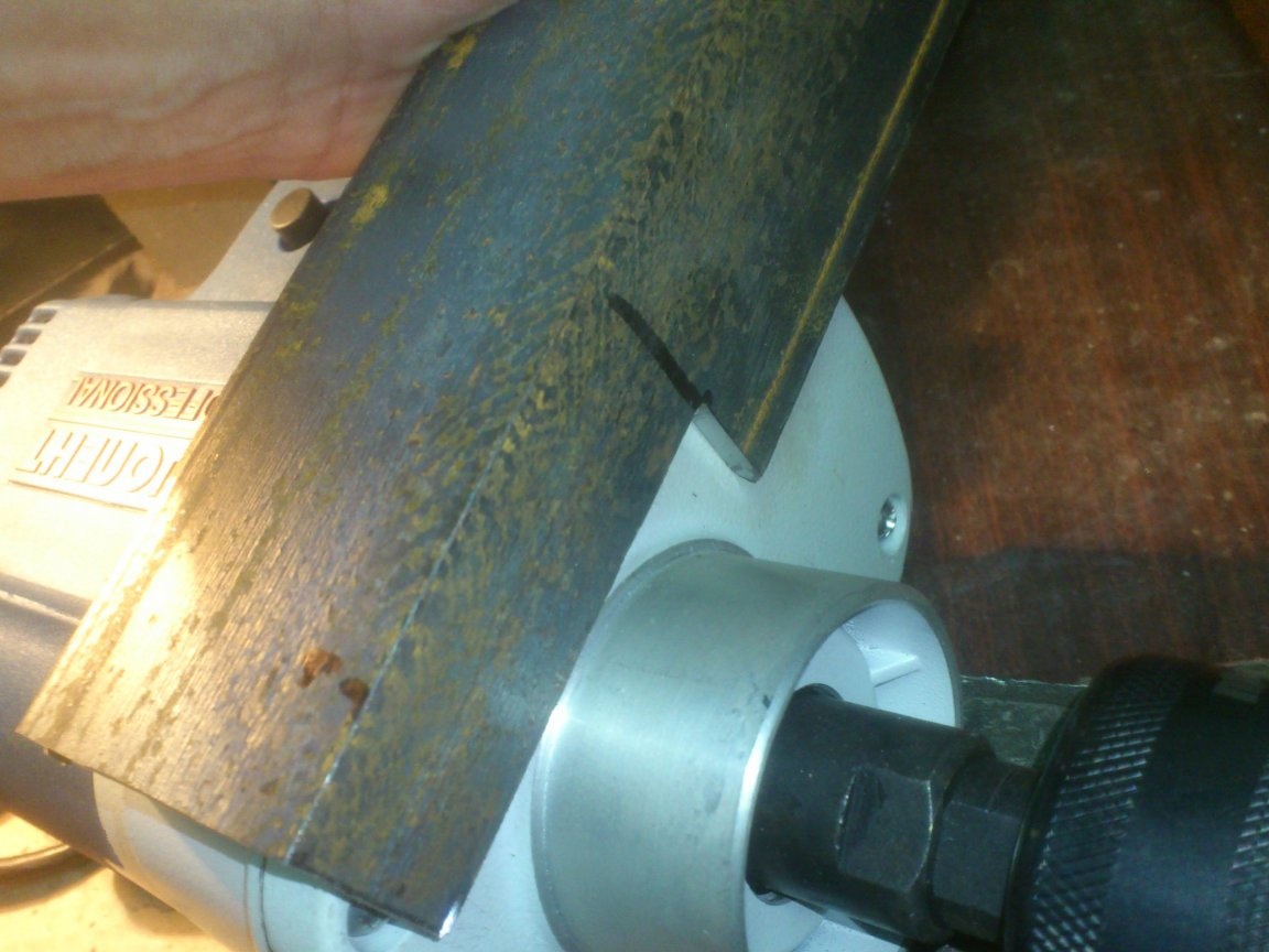
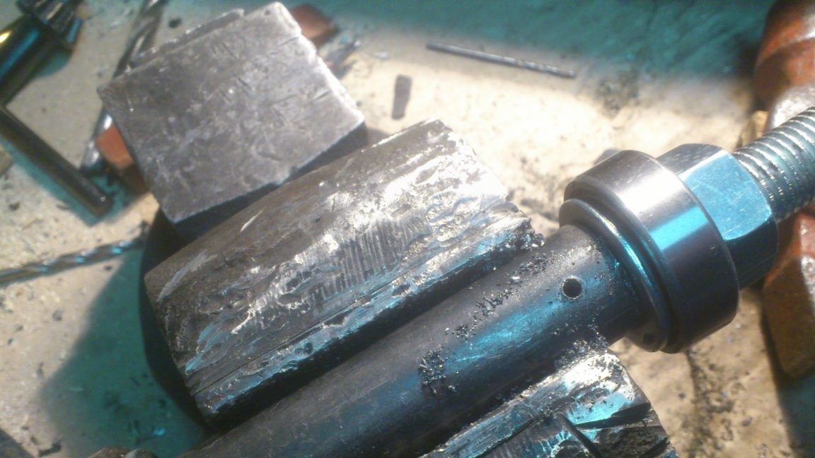
And behind them will be dressed bearings №202. Their inner bore hole is slightly smaller than the outer diameter (along the thread ridges) of the M16 stud. Therefore, I decided to sharpen the thread combs a little - the thread will still not bear any critical loads. Since I don’t have a lathe at hand, I got out of the situation as follows: I clamped the pin into the chuck of the mixer already installed on the unfinished bed, turned it on and slightly sharpened the thread combs with a grinder with an emery-petal wheel:
Then he put on both sides bearings. Now, having removed one side cover from the carriage, it is possible to install the shaft with bearings in the fittings from pipes ДУ32 and put the cover in place.
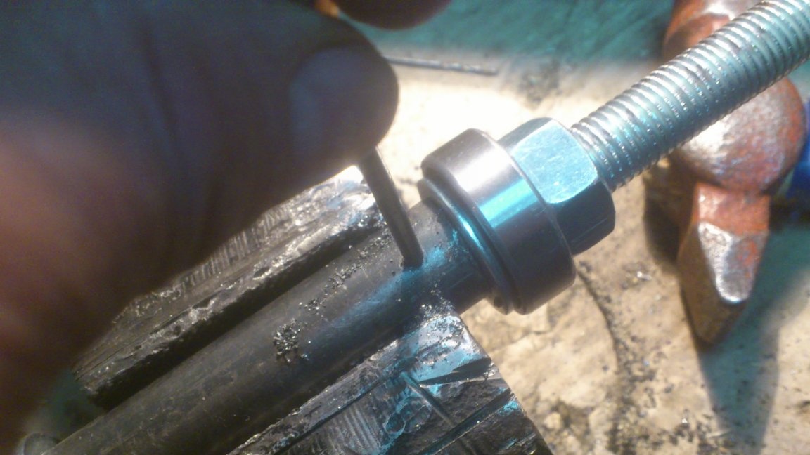
But before that, it is necessary to fix the pipe-drum on the pin-axis.Since there was no way to turn on the welding machine where I worked, and I didn’t want to go to the cottage, I came up with another way - I drilled a pipe on a hairpin and a hairpin in several places and hammered pins made of nails into it:
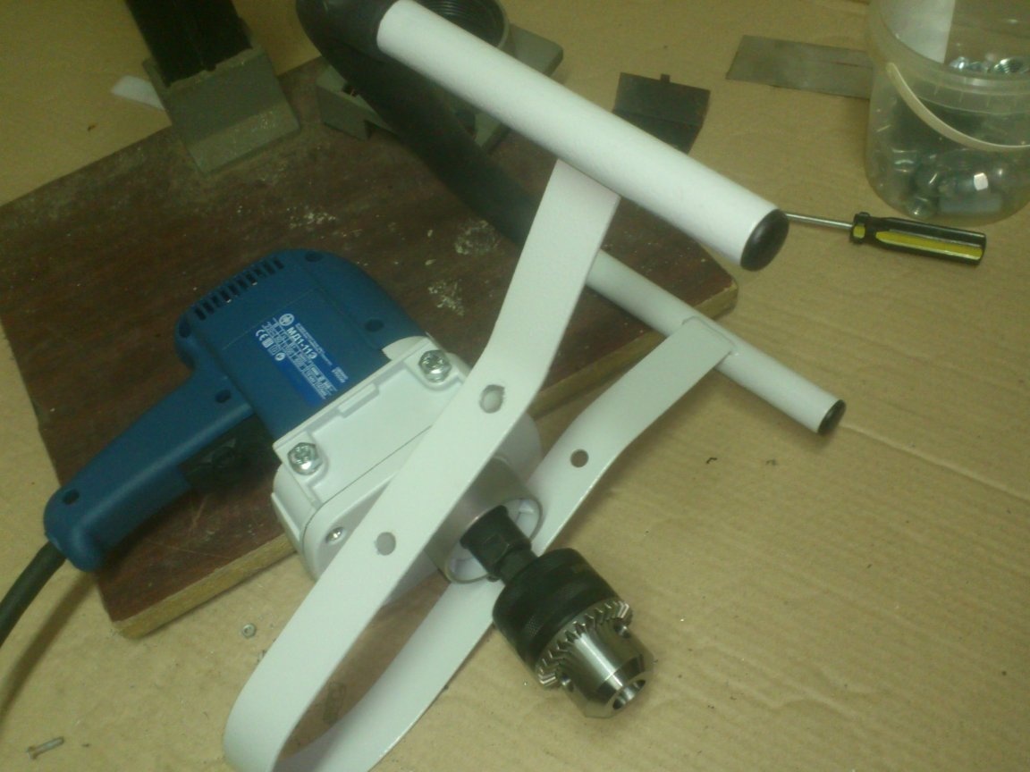
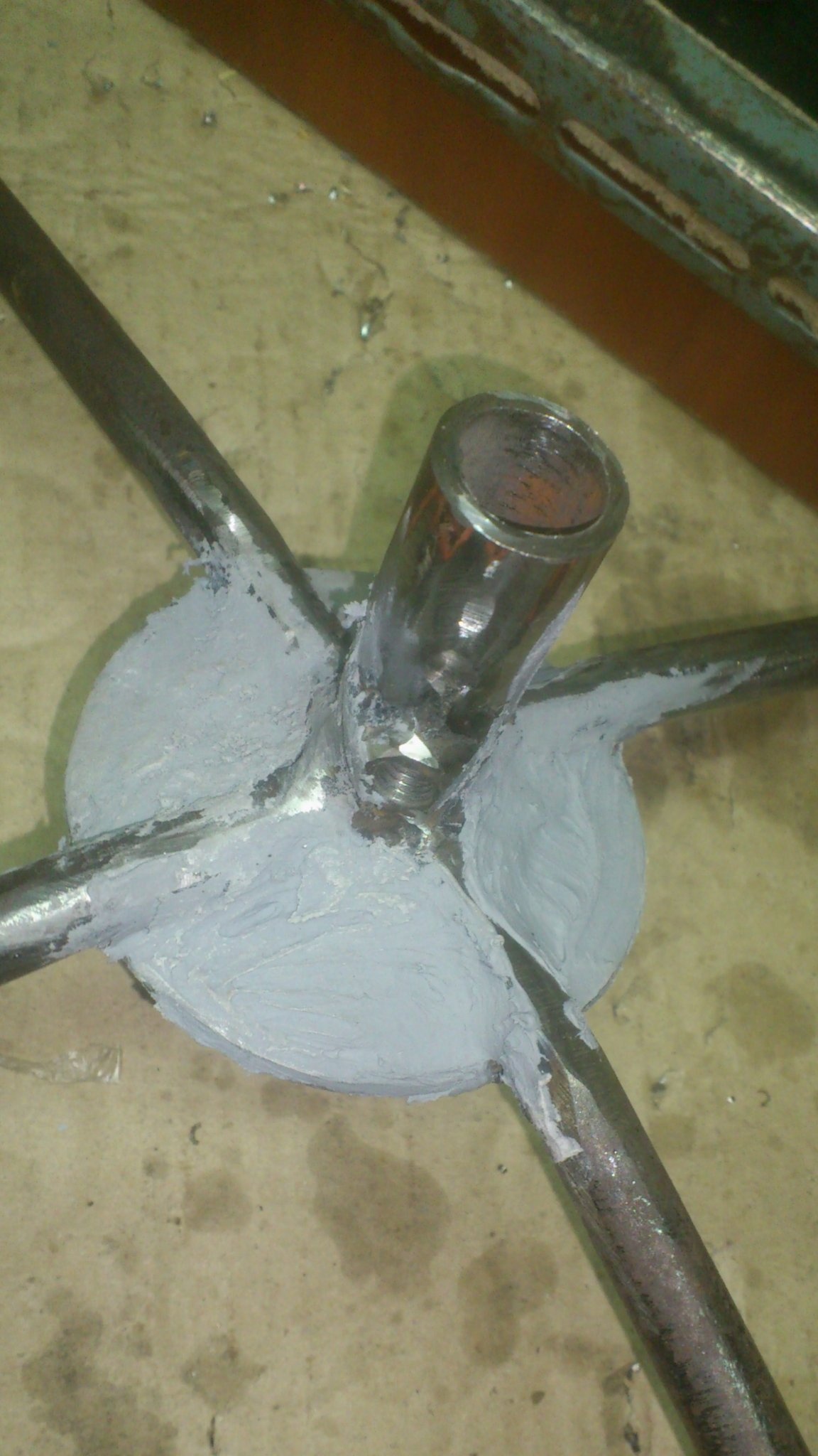
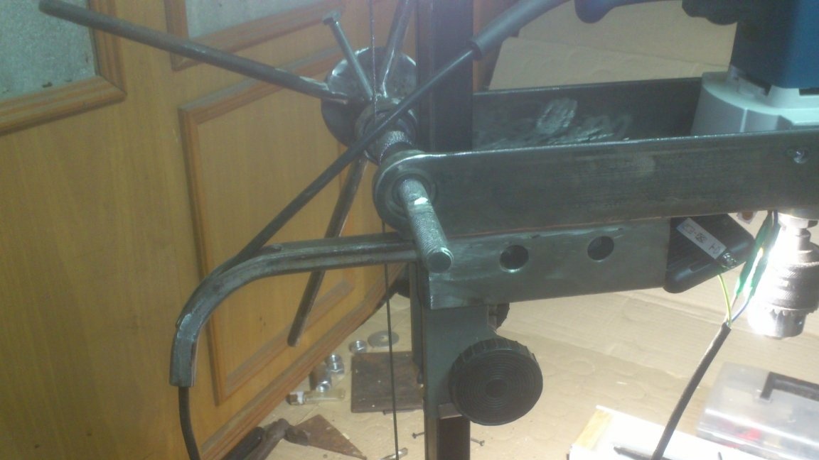
Now you need to make a "helm". I decided to make it out of four rods, with a diameter of 10 mm., Available in my possession and the M22 washer increased, specially purchased.
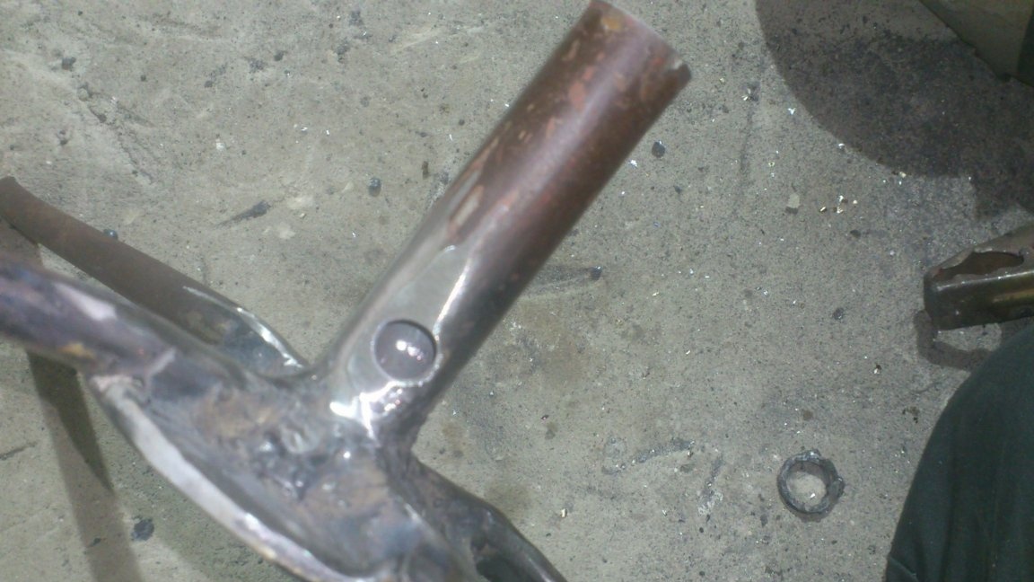
In the role of the hub will be the trim of the same pipe DU15:
To tighten the helm on the axis, I drilled a hole and welded an M10 nut. There will be a selection on the shaft, and the wheel hub will be tightly fixed with the M10 screw.
I couldn’t clean the accumulated splashes of scale, therefore, I just roughly rude this place with an auto-putty, which is overdue for four years, standing on my shelf))))))
With the lifting gear we’ll finish for now. Let’s focus on strengthening the bed itself.
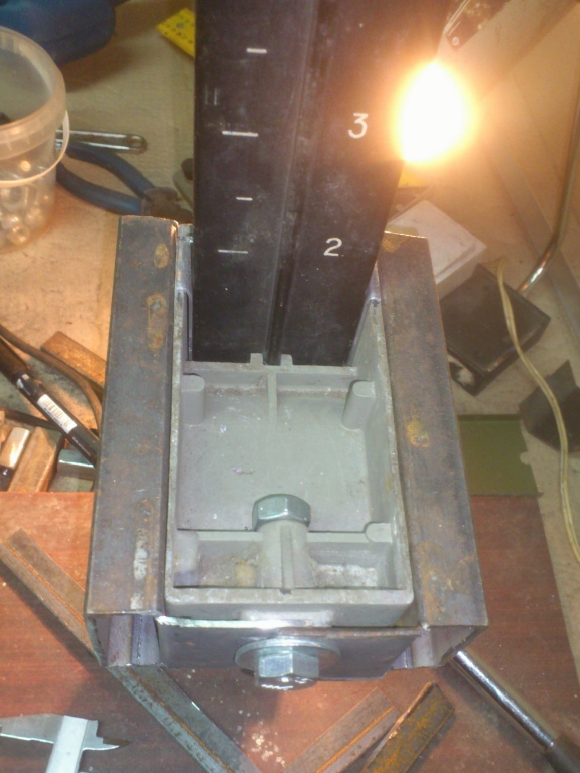
The vertical bar is hollow, made of aluminum. Although the wall thickness is quite large, but for my purposes it is rather flimsy. (I do not make a stand for a drill, but a powerful machine). Yes, and the rack is mounted on the table with three M6 screws screwed into aluminum. This is also no good ...
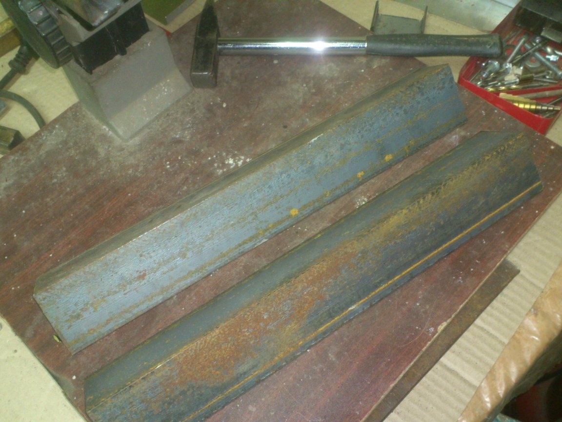
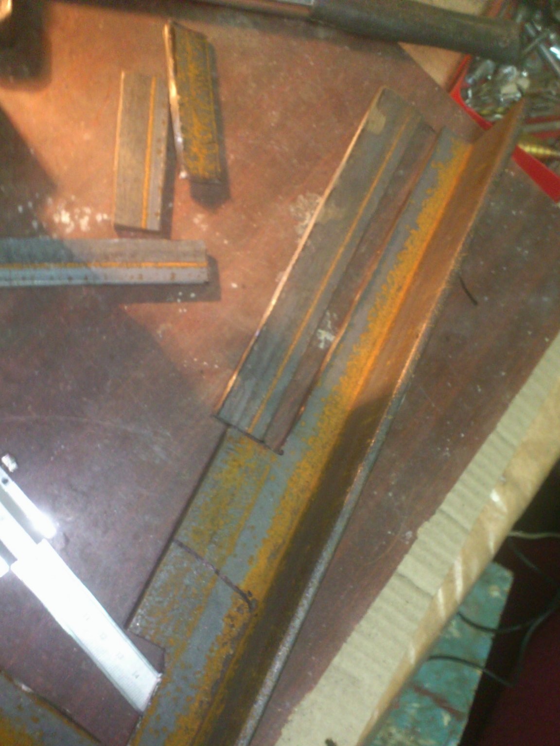
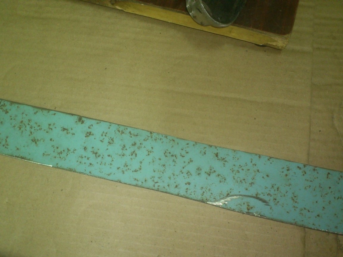
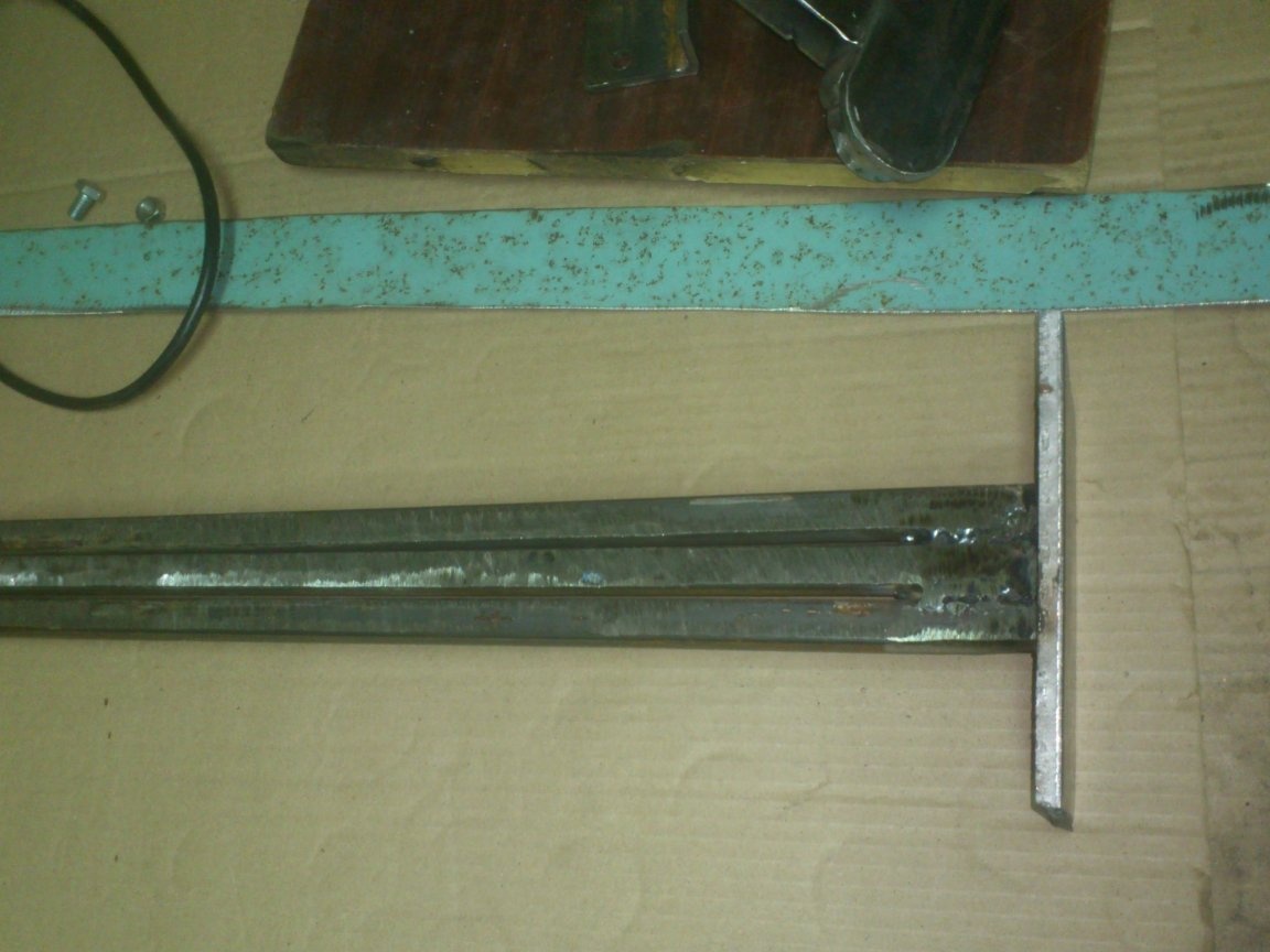
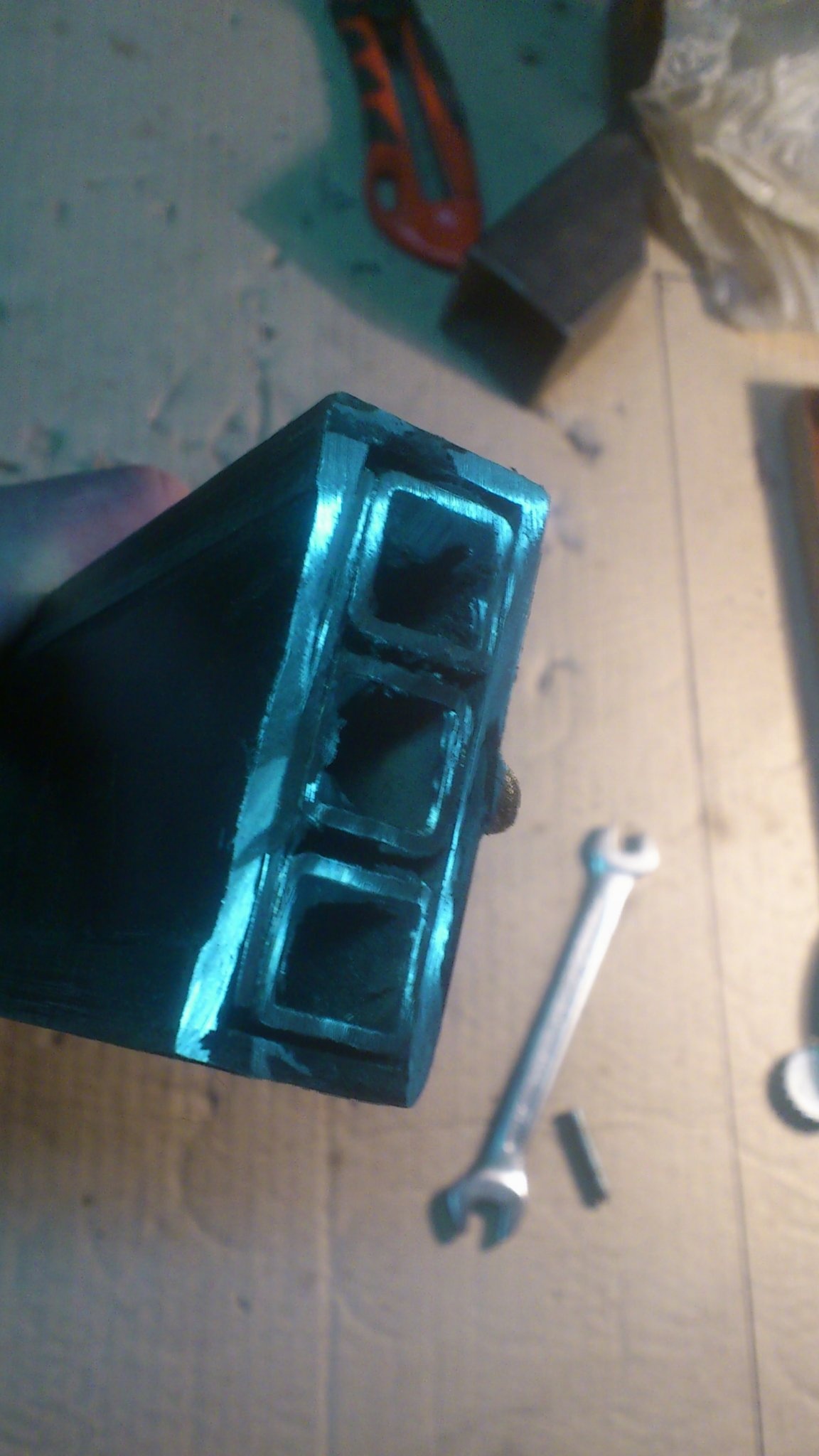
I decided to strengthen the rack with three profile pipes 15 by 15, placing them inside an aluminum rod.
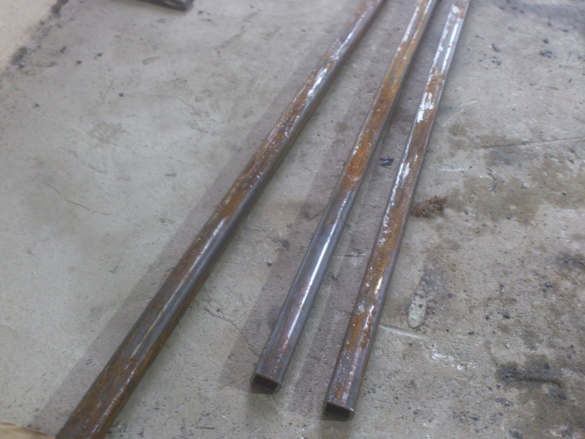
To strengthen the attachment point of the bar to the table, I welded these pipes to a sheet of metal, 8 mm thick. (This piece was lying in my scrap metal):
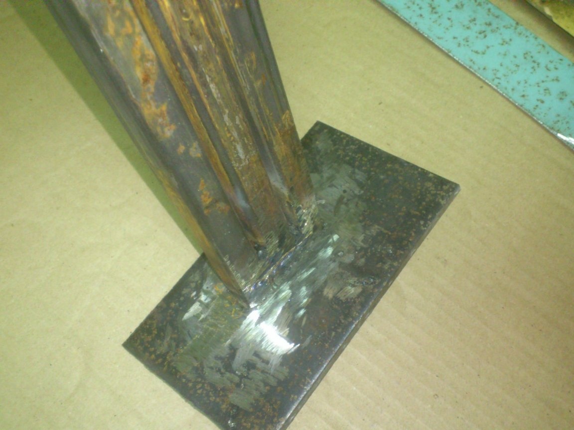
Between them, too, welded together:
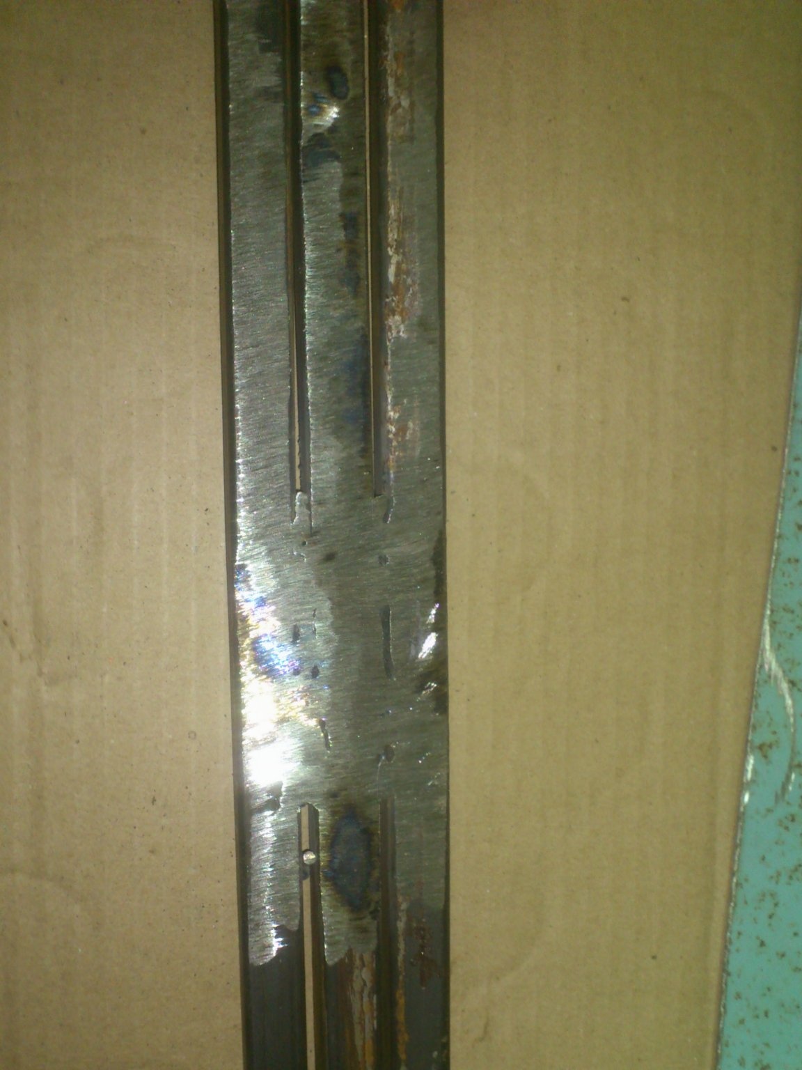
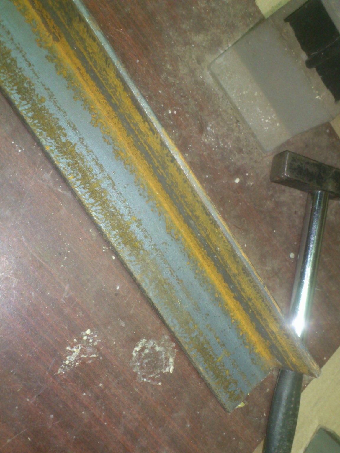
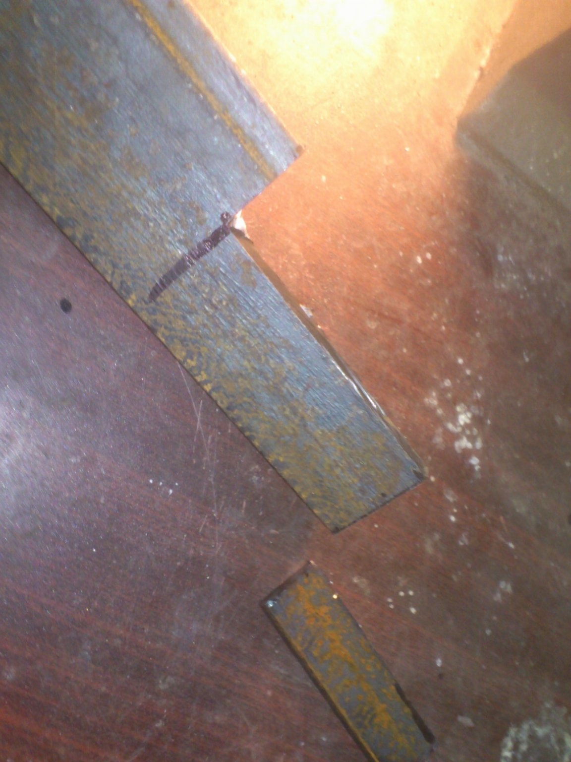
The inner cavity of the aluminum rod has a width of 16 mm. To tightly wedge my “reinforcement” inside, I cut out a strip of metal 1 mm thick from “scrap metal”:
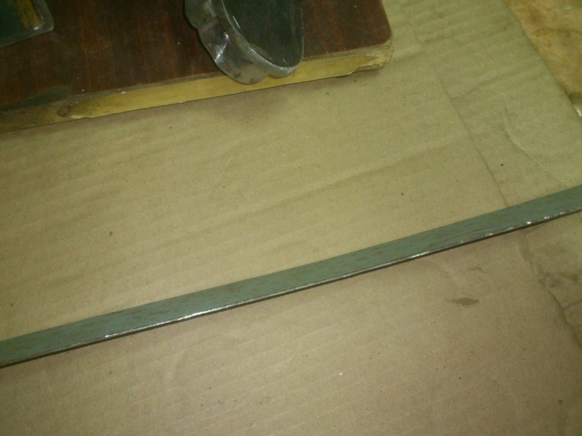
He put the rod on the reinforcing structure, and hammered in the strip: For a more tight connection "into a monolith", he filled the entire structure inside with epoxy glue. (I didn’t take pictures due to dirty hands))))
Now the table. The "native" table of the enlarger, made of chipboard, 16 mm thick (which, moreover, is more than 30 years old))), was not suitable for my machine.
I decided to make a new table from a piece of laminated moisture-proof plywood, 20 mm thick.
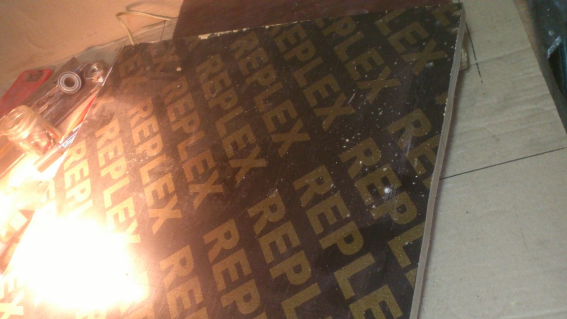
Such plywood is very strong, and I often use it in homemade products. It is quite expensive, but I do not buy it on purpose. All that is needed is to drive to the nearest construction site, where construction houses with a monolithic frame and ask for trim, or removed formwork.)))). On occasion, I always gain full trunk))).
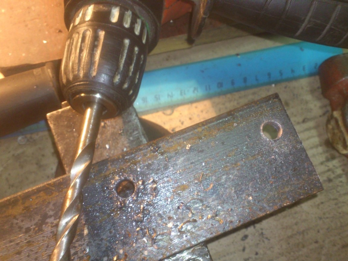
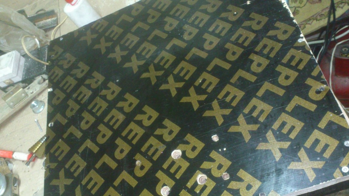
I made a new table more than the old one. Having cut out the required size, I drilled the mounting holes for the rack mount:
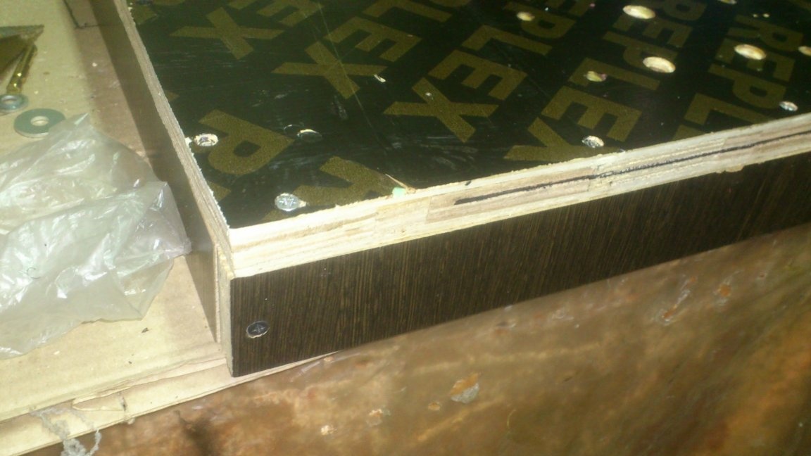
I screwed planks of chipboard around the table perimeter, raising the table 5 centimeters on these "legs":
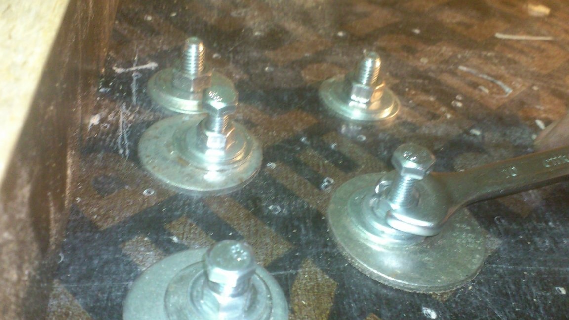
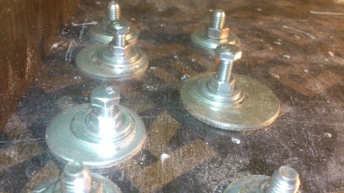
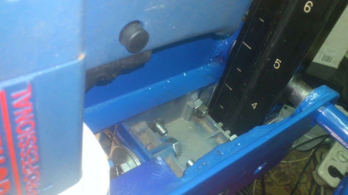
I drilled four holes in the corners of the lower base plate. I fixed the rack with M10 bolts:
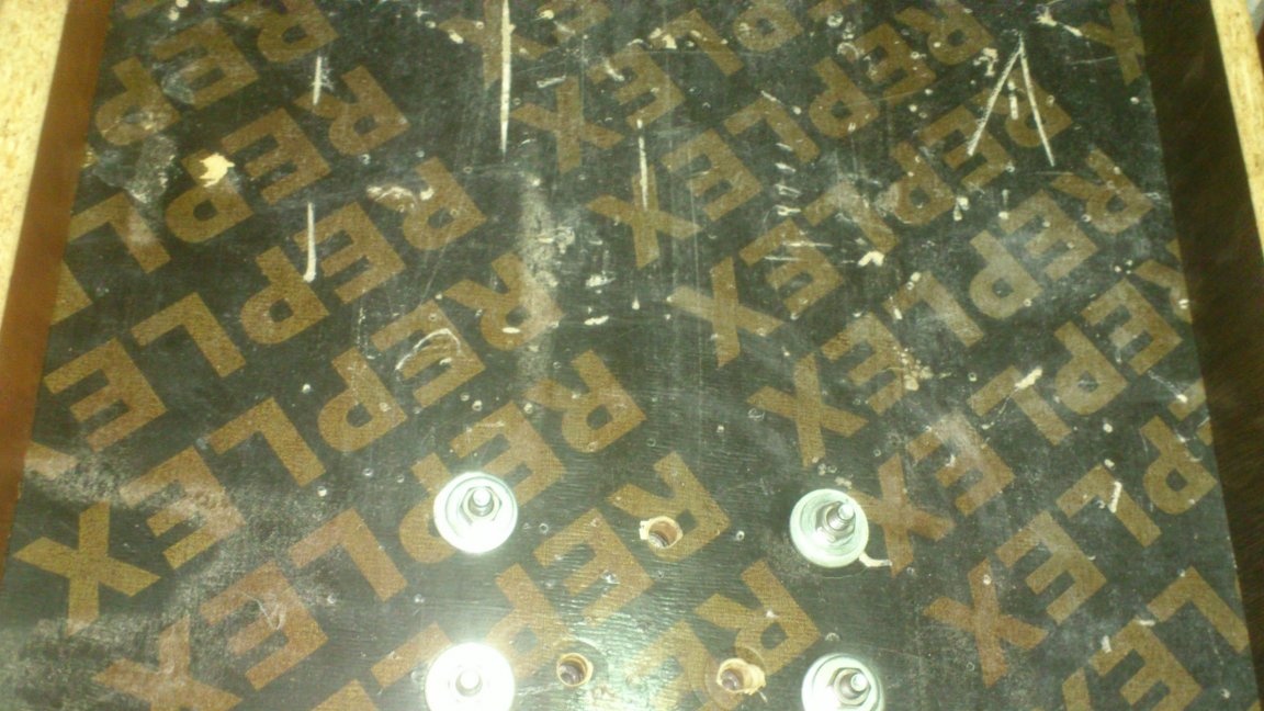
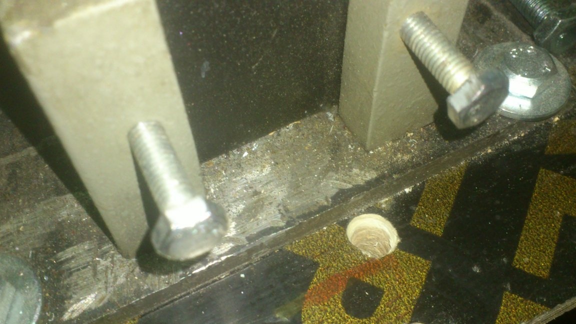
In addition, it must be fixed with "native" M6 screws. Since they are screwed into aluminum (But the screws still need to be changed), I decided to use screws of a much larger length, screwing on them with nuts that had already been clamped “with all the dope”)))) Fortunately, I have five “under the table” centimeters of space to support. Let them stick out!)))):
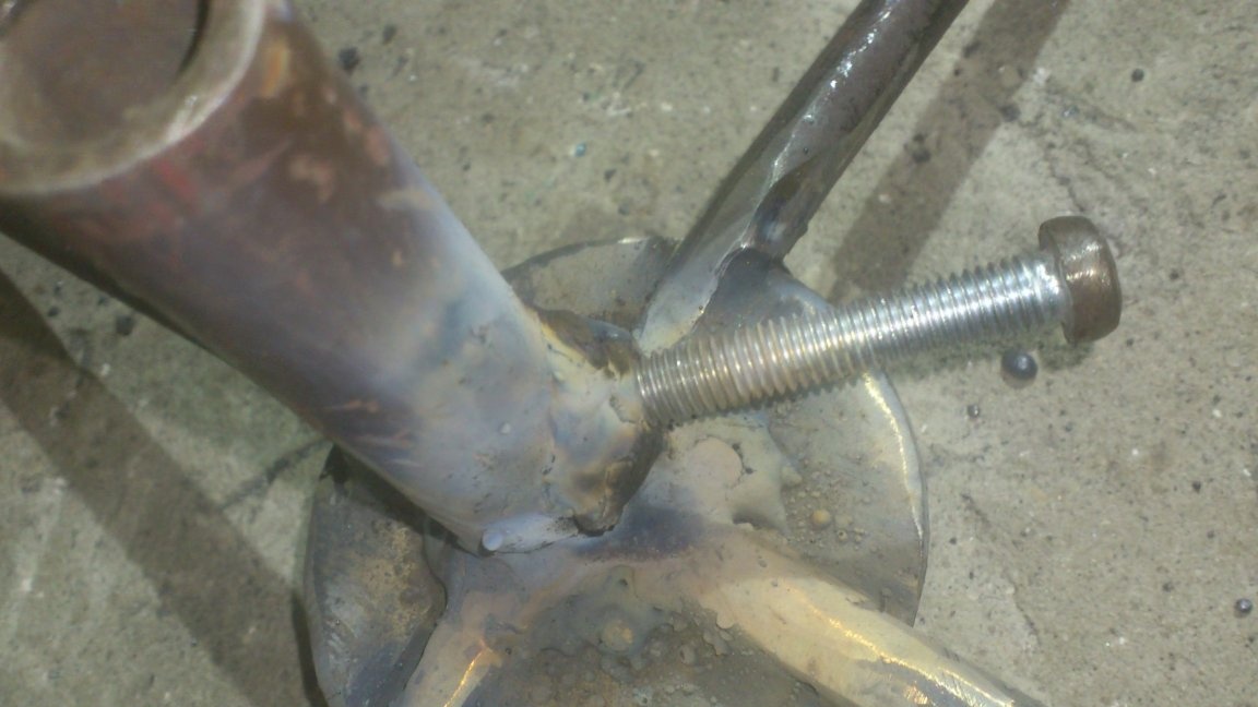
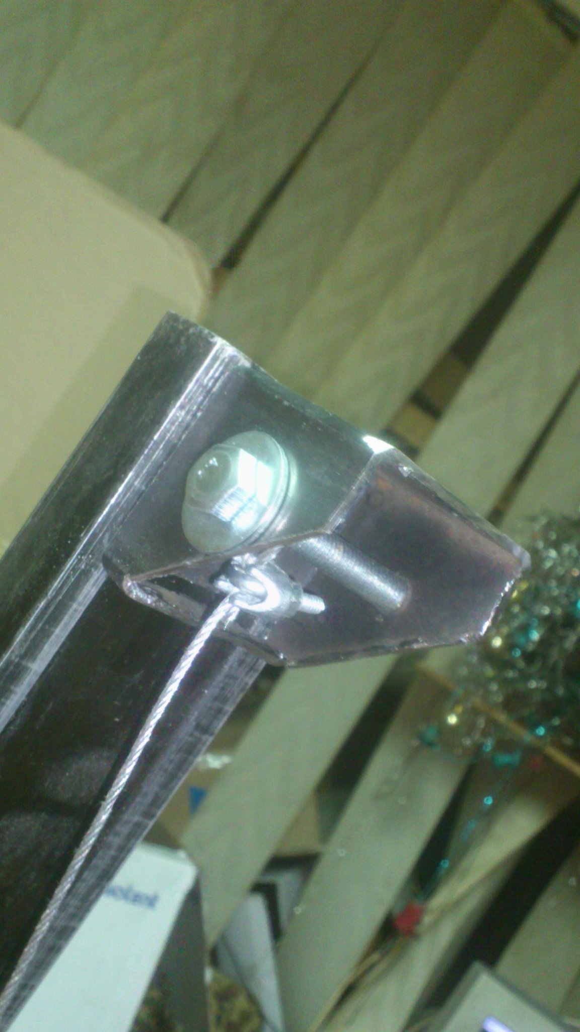
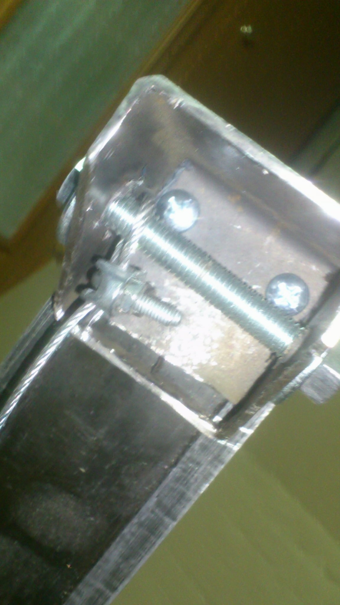
At the back, opposite the rod, I drilled a hole for the cable fixing bolt (it will also be a tension):
For fastening and tightening the cable, I used a regular bolt with an M8 nut. Under the head of the bolt, for fastening the cable in it, I put on a corner, which I cut from the trim of the profile pipe:

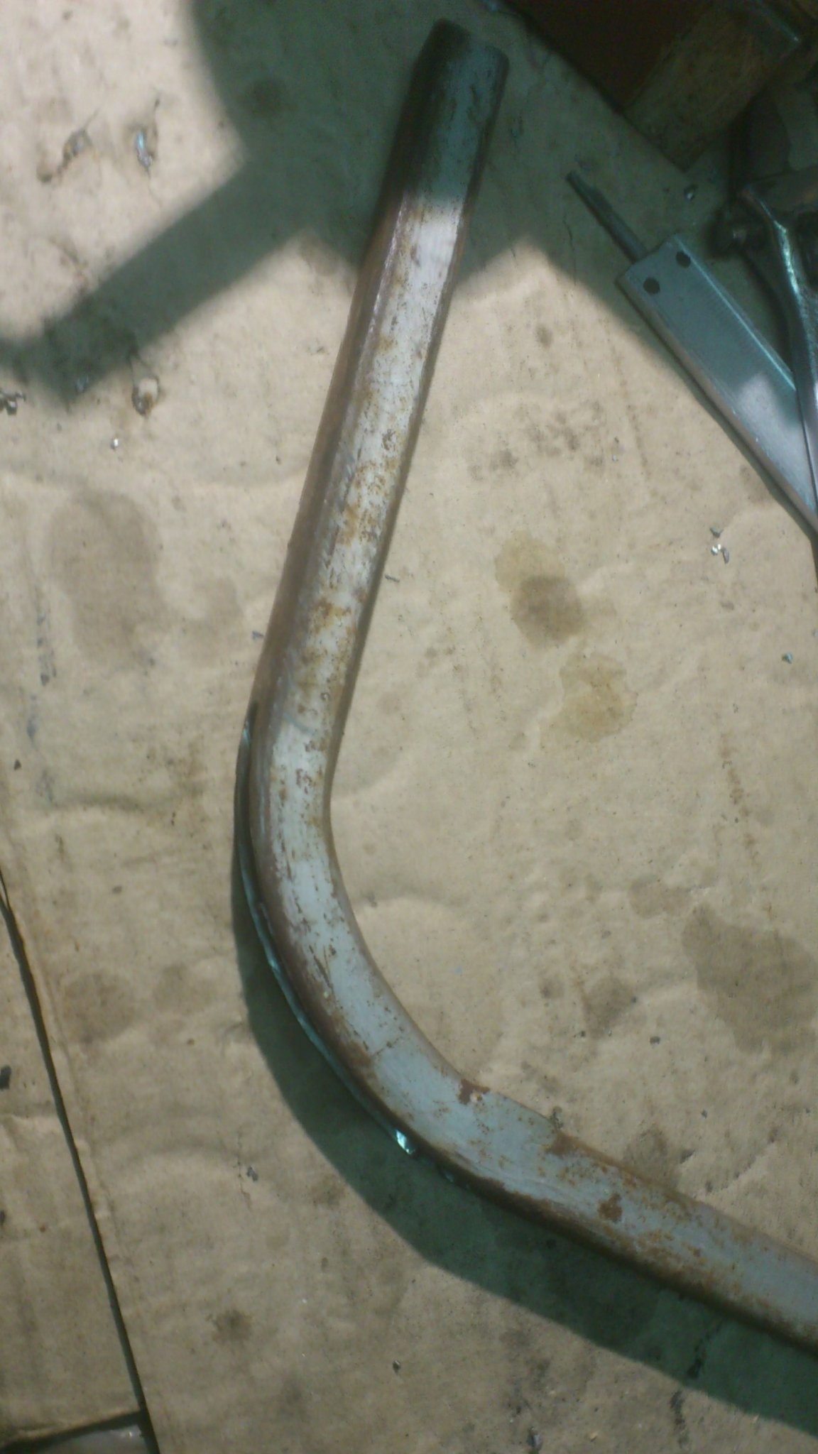
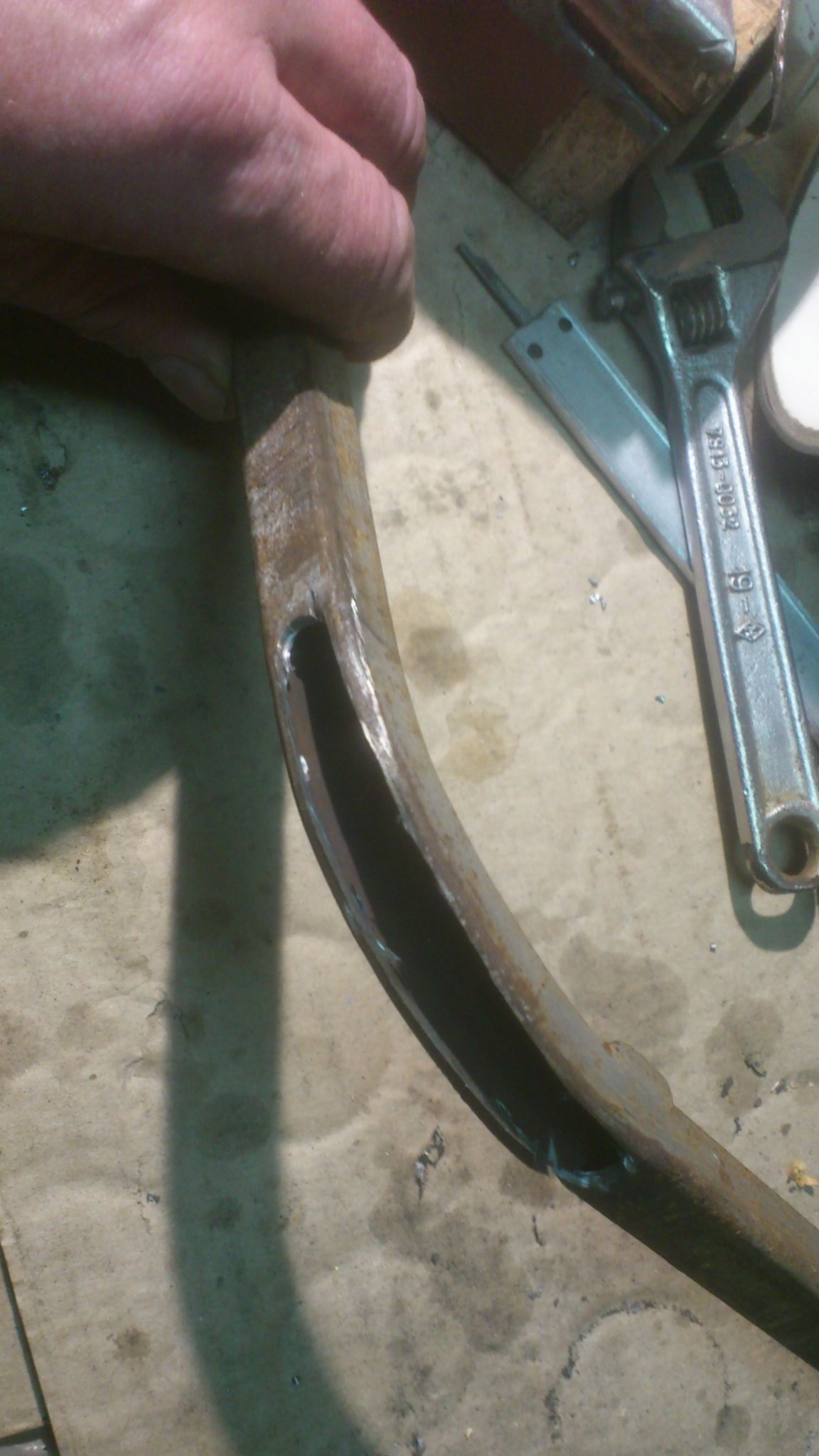
Top cable also needs to be fixed. To do this, I made a bracket from the one that fell under my arm, trimming the profile pipe 50 to 50. He immediately was even with a "slanting edge")))
I fixed it in the upper part of the rack with two M6 bolts, drilling the necessary holes for them in the rack:
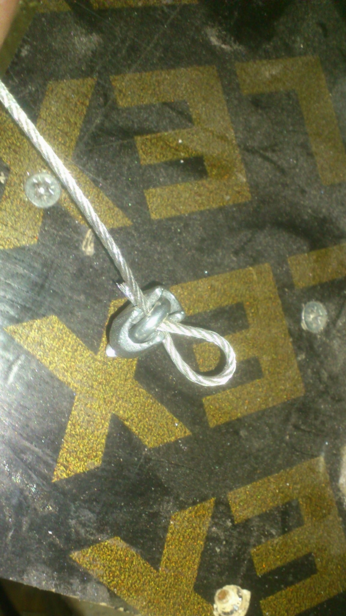
The cable itself was found in a box with the remains of materials after the manufacture of bows and crossbows:
Let's take a table again.
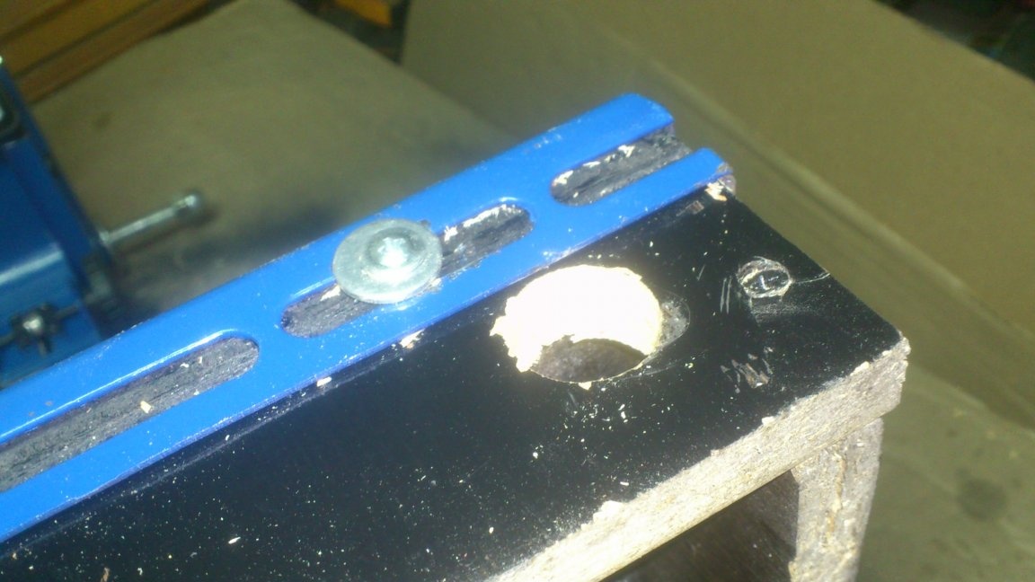
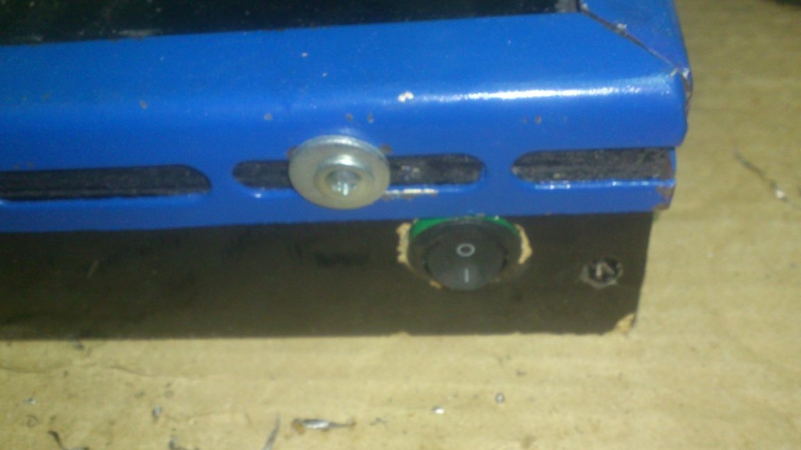
In front of the table. Drill a hole for the "emergency fungus."
I was lying scattered around such metal elements.
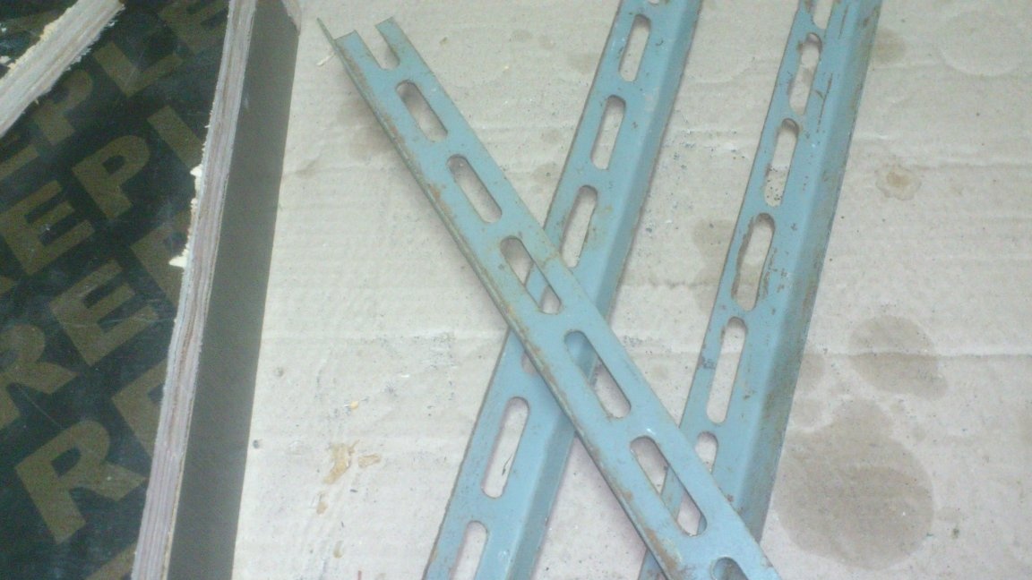
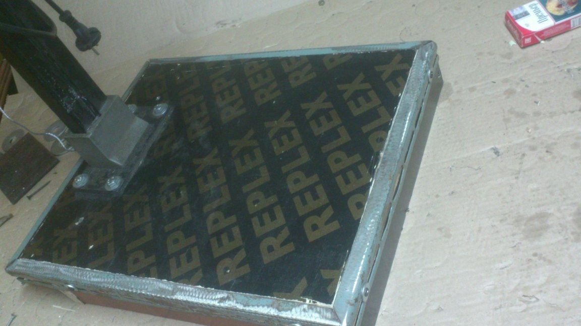
Apparently, in the past it was the details of a rack, or hardware rack. I decided to frame the edges of the table with them. After all, the ends of the plywood will be beaten with metal blanks, if this is not done.
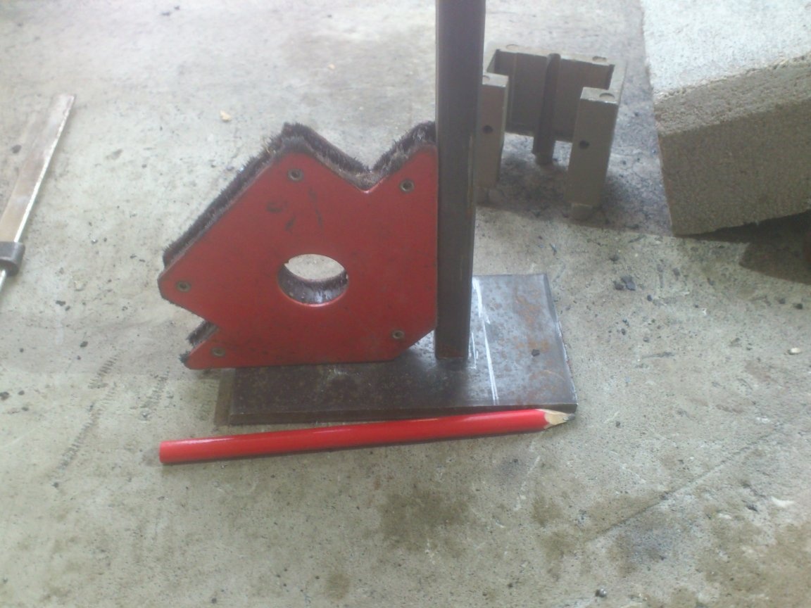
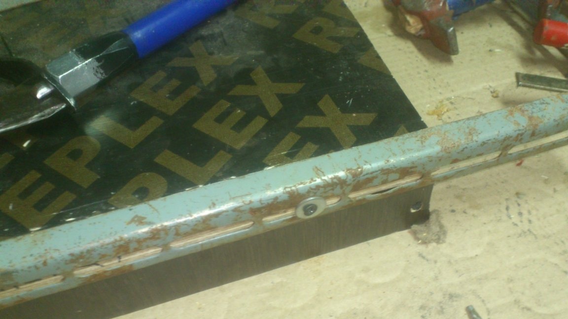
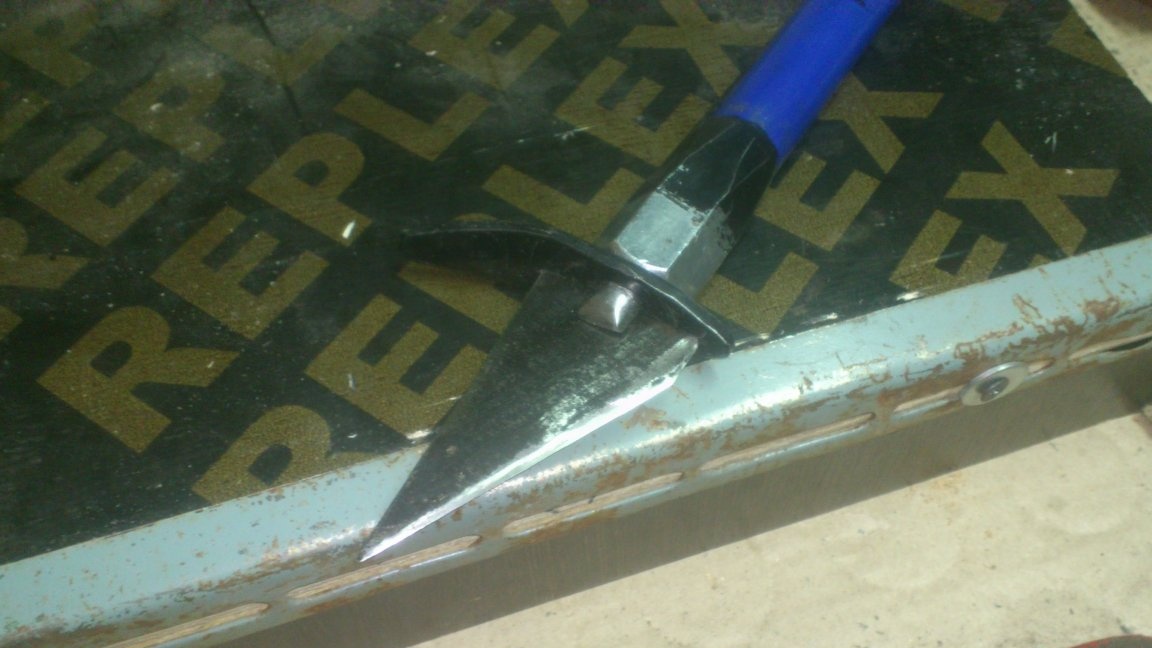
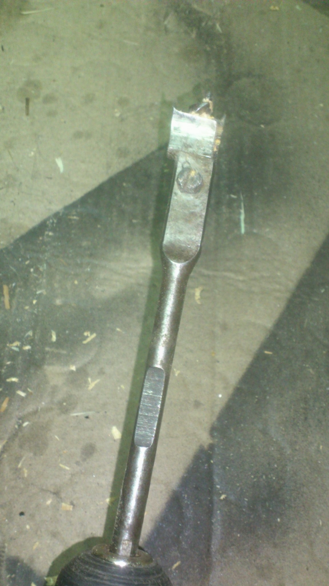
I tried on the corners in their places, outlined with a pencil, and, with the help of my homemade tool cut along these lines, and removed several layers from plywood - the metal edging must be flush flush, otherwise long workpieces will rest against it and the perpendicular to drilling will be violated.
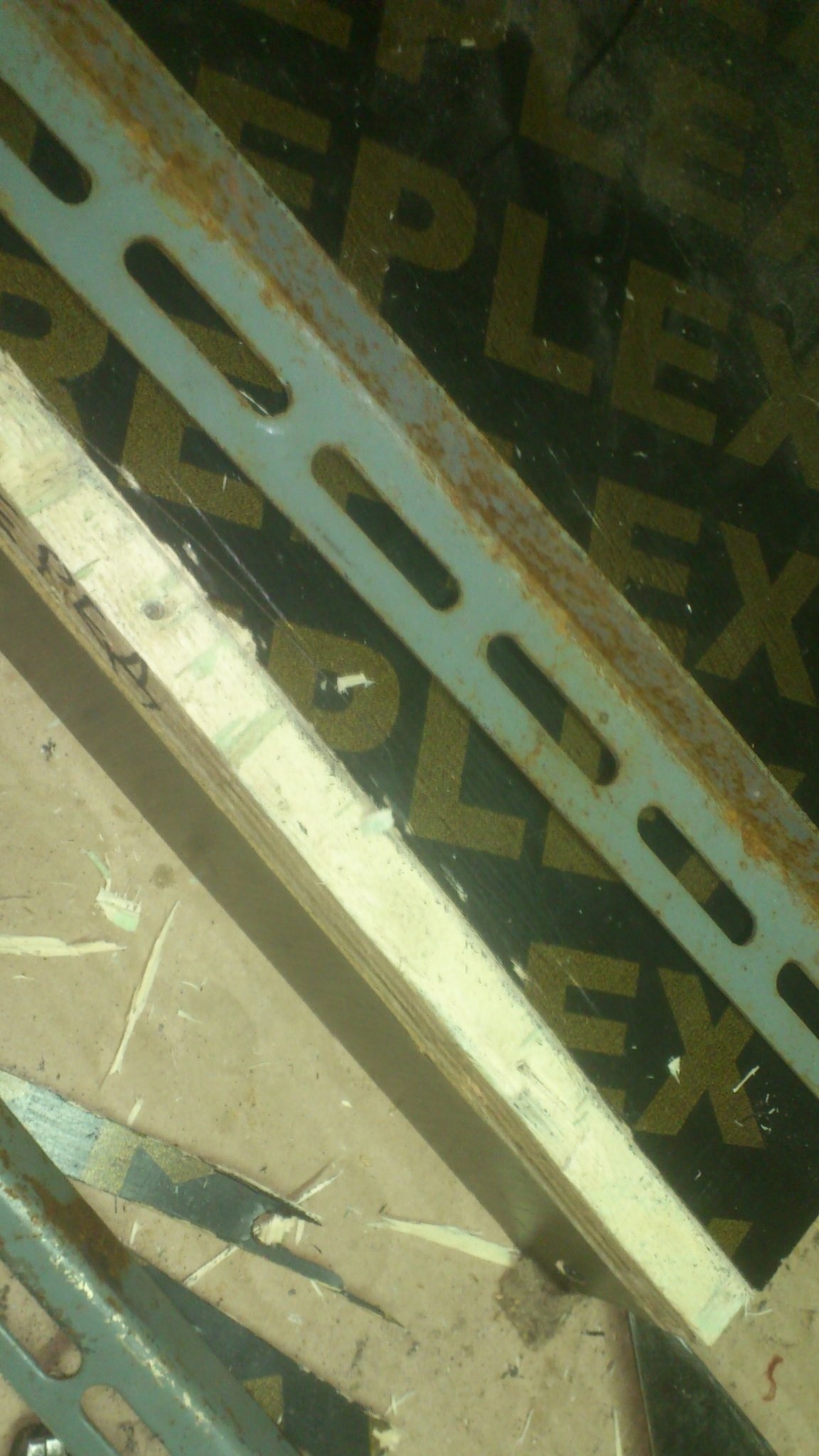
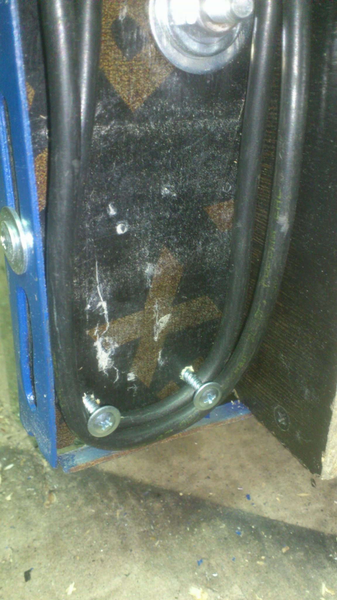
He secured the edging with screws with a pres washer, laying the M6 washers.
And one more thing I came across: the cord! The fact is that I do not want to turn the machine on and off with the “native” button of the mixer. This is not convenient, and, importantly, not safe !. The power in the machine is quite high, even excessive! At the test stage, I drilled a metal channel with a 16 mm drill, and in the end I got the workpiece out of my hands, although I was ready to bite when the drill came out. I then pulled the plug out of the socket, but I remember the feeling when you see a heavy piece of iron rotating on a drill and wait for it to fly away at great speed if it suddenly breaks.)))) And at that time you bend down to the socket, substituting your head on a possible flight path of the channel!)))))
And therefore, any machine in the front should have a "red fungus" - an emergency stop button, which, even if you screw a sleeve on the drill, you can press it with your stomach)))) ...
At the same time, I don’t want to “firmly tie” the mixer to the machine! I’m not going to work with him constantly and professionally! I will need it both as a mixer and as a machine - it follows that it should be easily disconnected ...
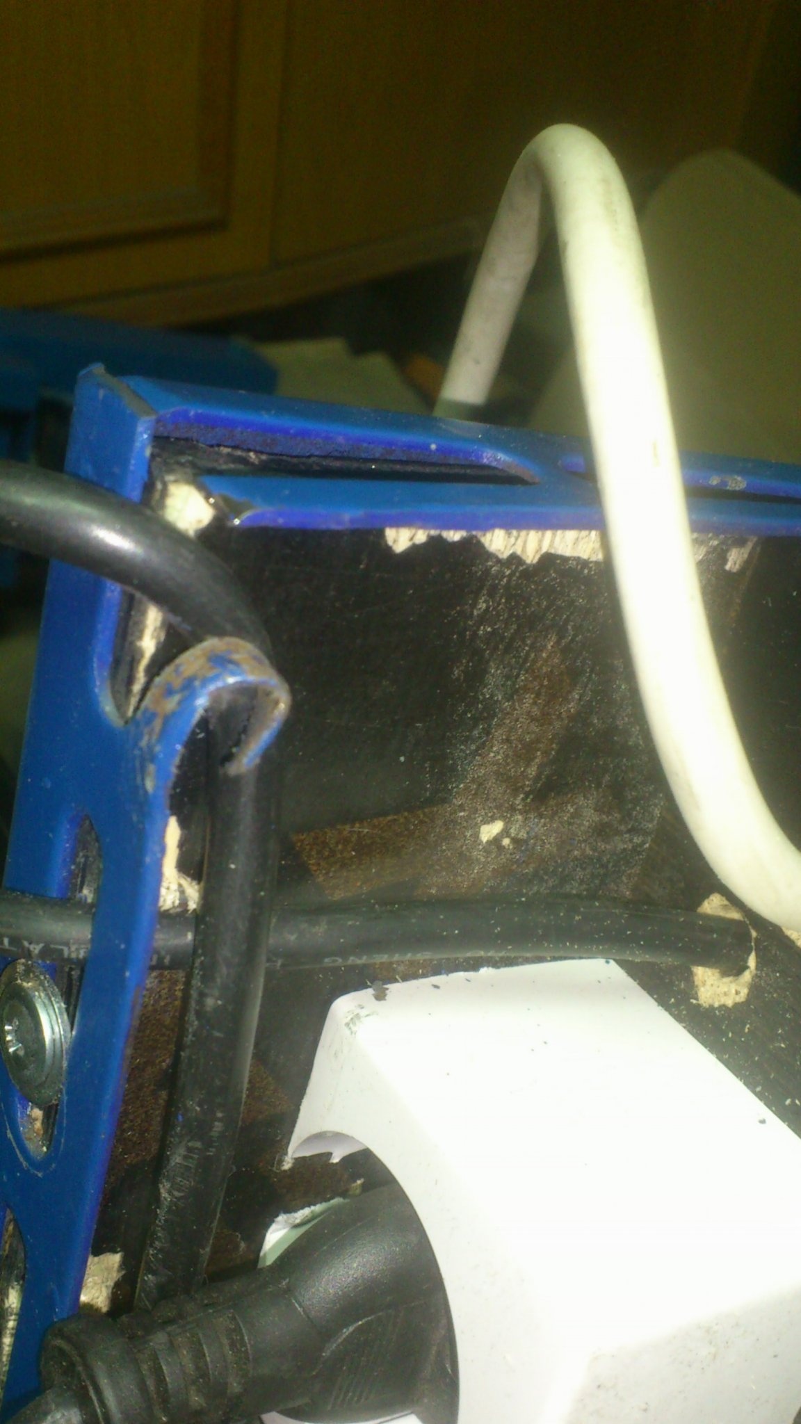
To solve this problem, I secured an external layout socket under the table. (The back wall is prudently “recessed.” Now, after installing the mixer on the bed, you can simply plug it into this socket, fix the native button, and turn it on and off with the fungus button in front. (The bed for this will have its own cord, which will be included in the network.)
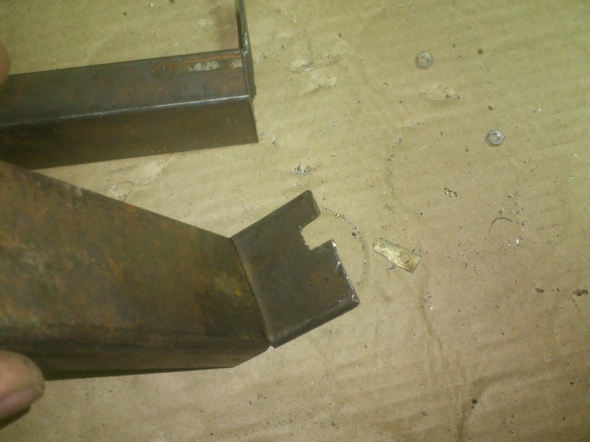
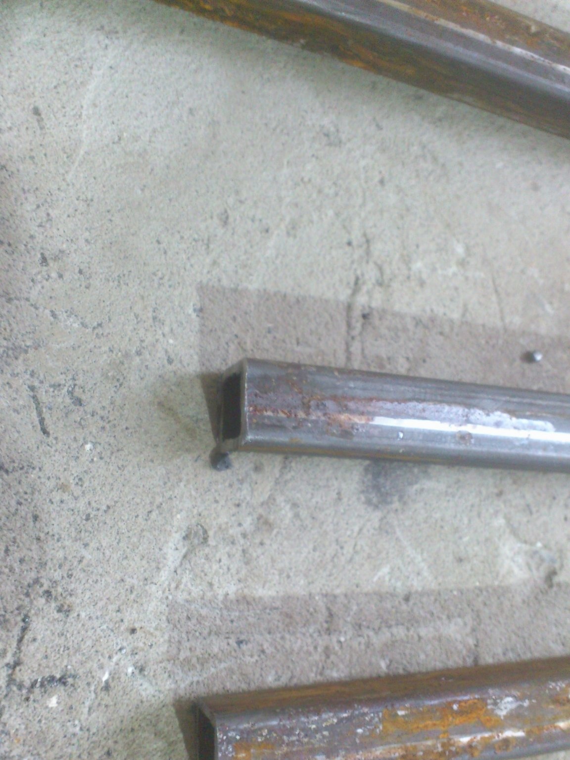
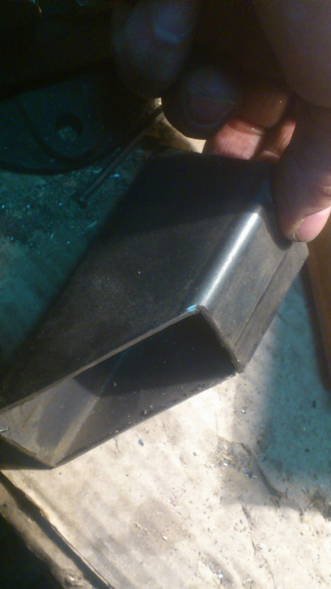
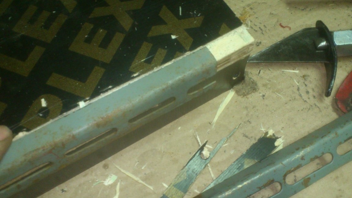
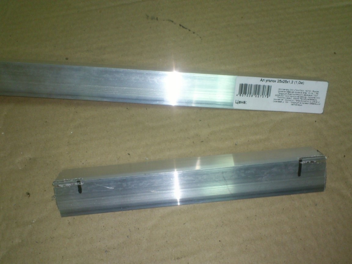
But here, the mixer cord! It is too long and may fall under the cables when moving the carriage. In order to avoid this, I made a cable guide from the profile pipe 15 to 15. I bent it on my homemade pipe bender, and made a cut along the upper plane, which at the end goes to the side plane.
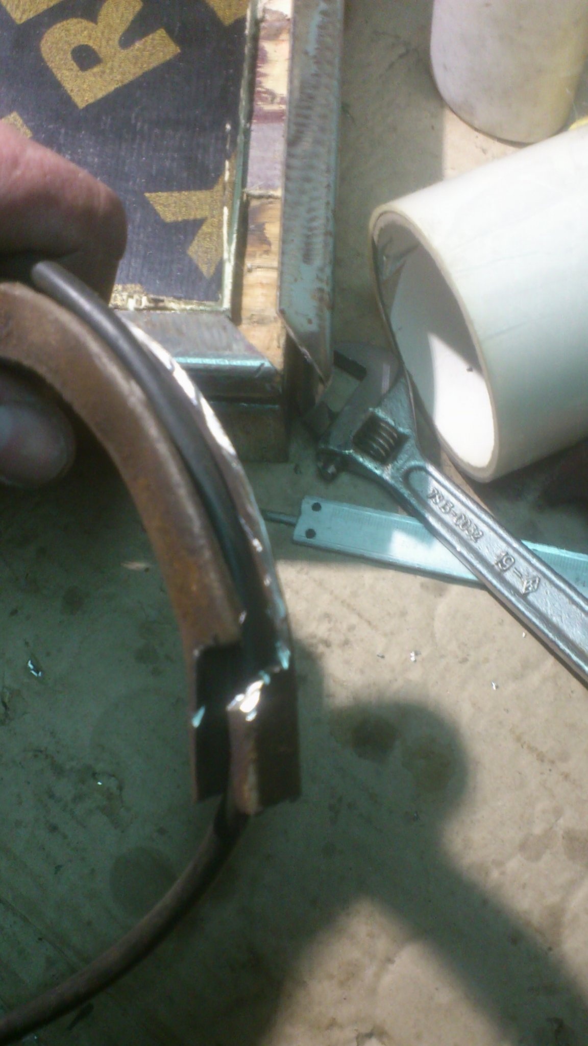
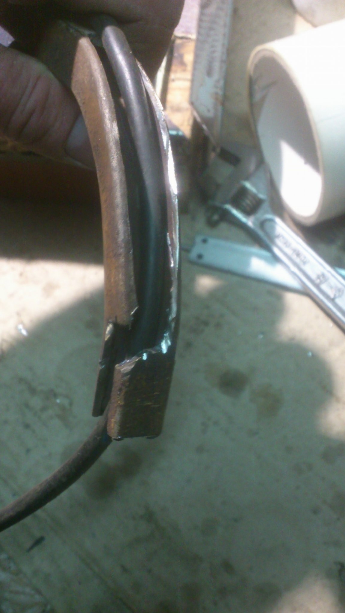
I insert it into the end of the lining and lay the cable in it. Now, when lowering the carriage, it lays far away from the cables:
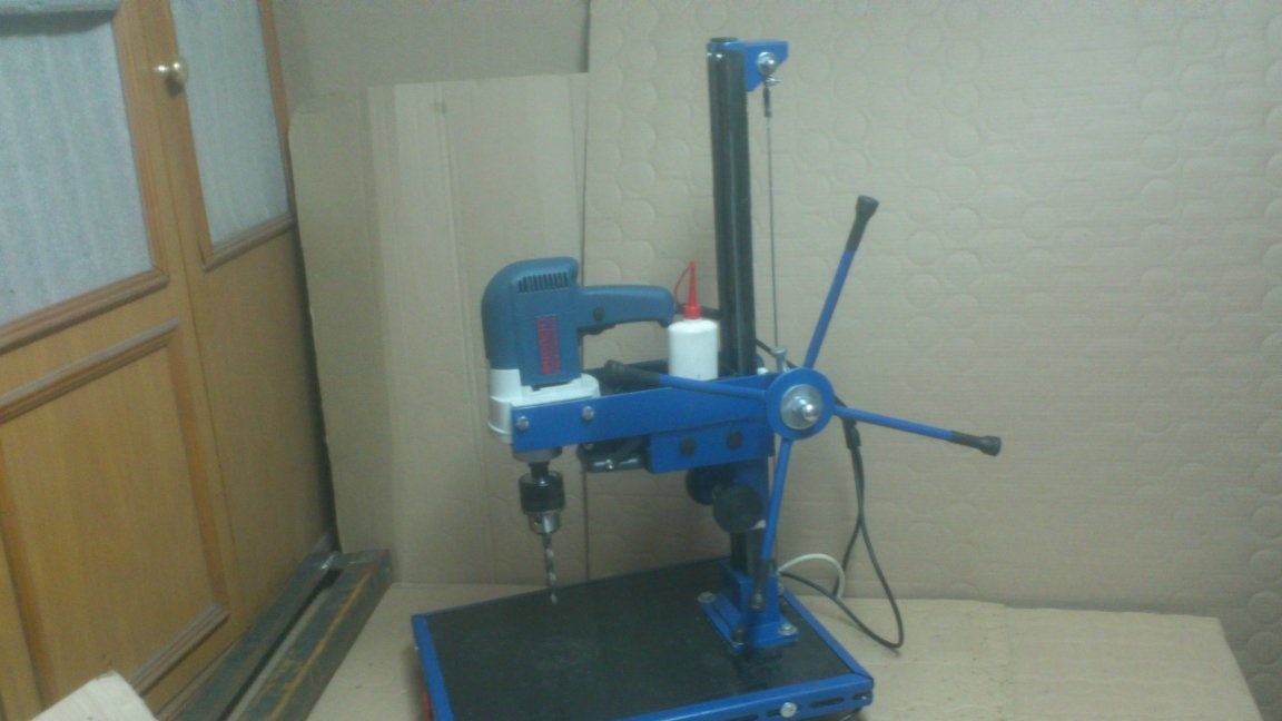
Almost ready. We disassemble, paint ...
After painting - "comb", as I call this process)))) I clog plastic plugs wherever there are open ends. Round I close the "filling holes" of the bolts for fastening the pads.
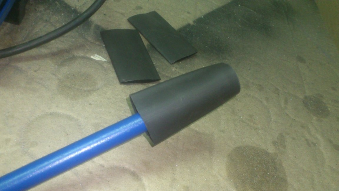
Using the same plugs for the DU15 pipe, I decide to make the “knobs” at the ends of the handlebars. I do not use it traditionally - they are intended for clogging inside, I put them on top (For density I had to wind up a bit of electrical tape ... (It's a pity there wasn’t found an epic-blue !!! I applied green)))):
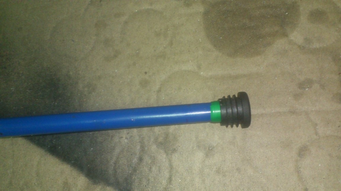
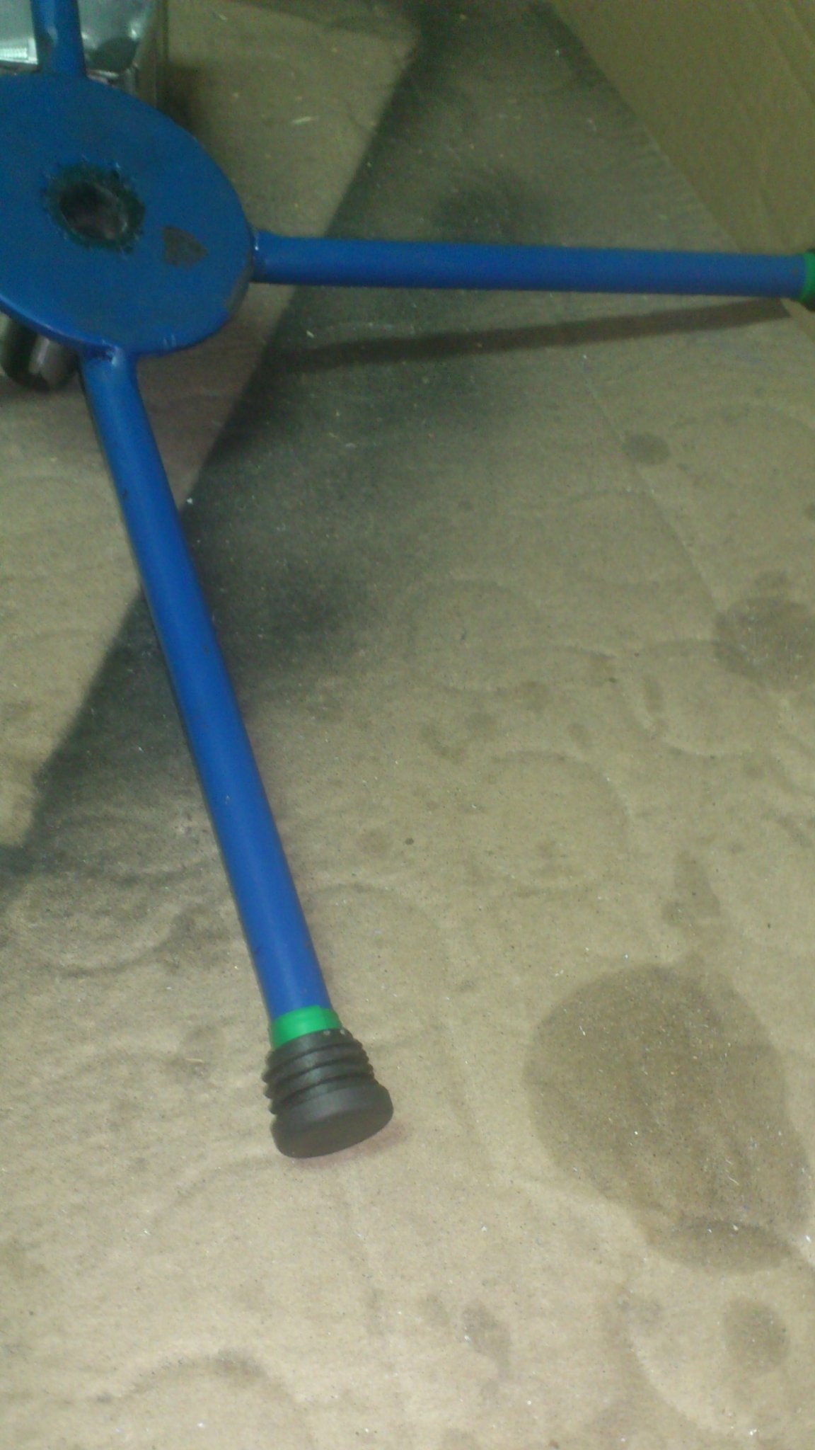
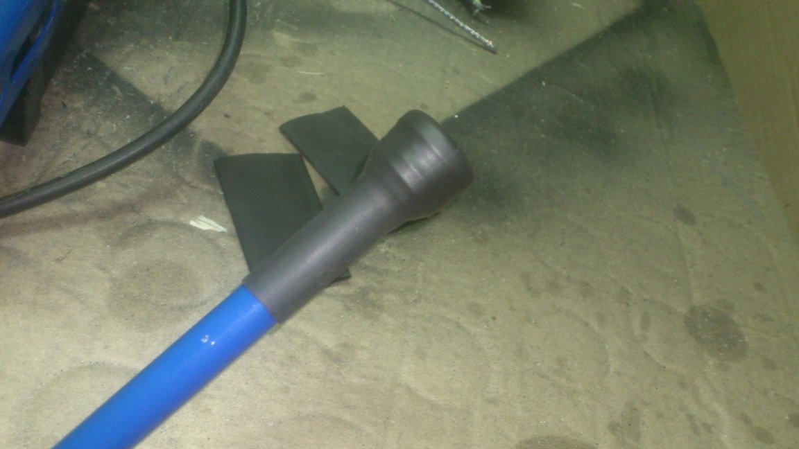
Upstairs I put pieces of heat-shrink tubing and hug a hairdryer:
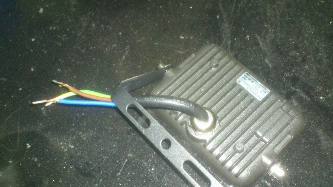
The machine needs lighting. To do this, I purchased a small ten-watt diode floodlight:
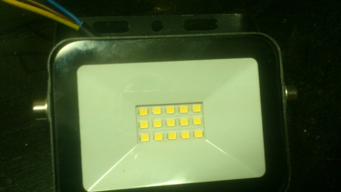
Since the mixer is moved forward, there is enough space between it and the carriage to accommodate the spotlight. I didn’t even have to redo anything. I just put the mounting bracket of the spotlight under the central screw for attaching the plates to the carriage, providing it with a wide (enlarged) washer:
This placement of the spotlight turned out to be very convenient - it is the working area that is brightly lit. At the same time, there is no likelihood that it will "get in your eyes." I laid his cable inside the cover plate and led it out back into the same guide, in which the mixer cable also fits. He lifted the carriage to full height and passed the cable into the hole drilled behind the table, and there he connected it with the machine’s power cable (long PVA))) through the switch, which he placed on the front end of the table on the right ...
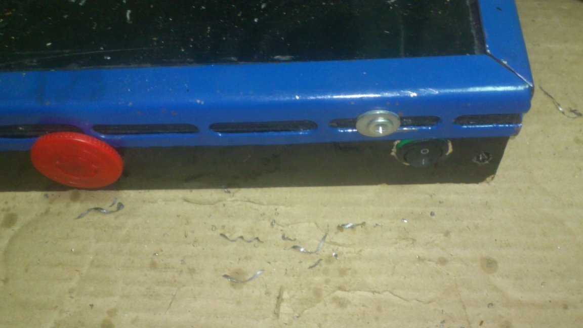
With this a little embarrassment happened))). I drilled a hole for the switch, which was in stock:
And here, under my foot something is crunching)))).I look - my little button))). She fell from the table, I stepped on it ...
Hmmm ... There is no second one ... I put "temporarily" the one that I could find ... But it is a little less ... I had to rewind the insulating tape))):
Then, like ... I’ll buy and change! ... (Oh ... Even the weakest believe it!))) Nothing is more permanent than temporary ... Especially if it works properly ..))) )
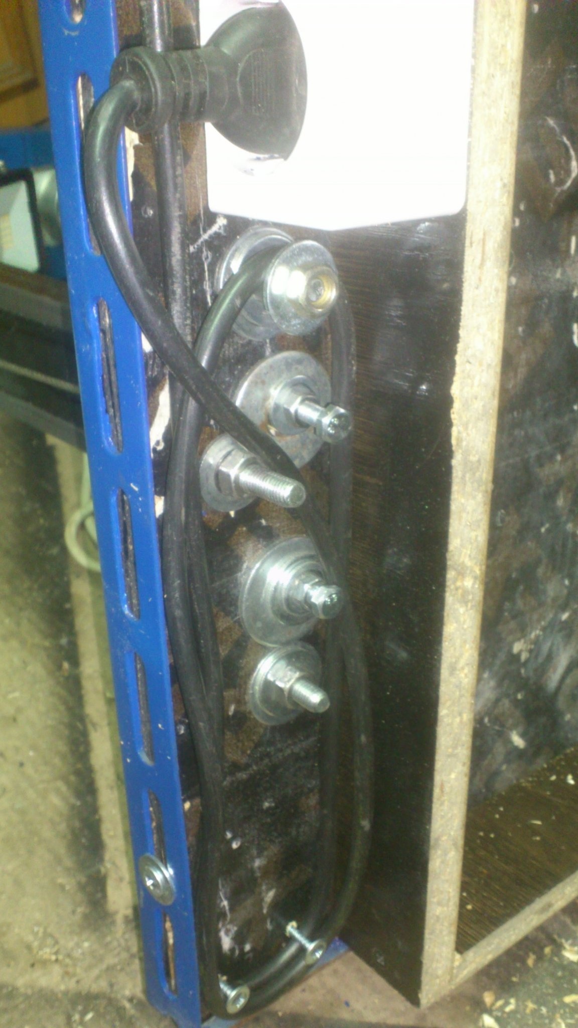
As already said, the mixer I plug into the outlet, located behind the ledge of the table. (I had to cut it a little ... I did not fit.
And the excess cable with the carriage raised to the maximum is wound on the back (under the table) on one side of the protruding rack mounting bolt, which I supplied with a nut and an enlarged washer, and on the other, on a specially screwed pair of screws with a press washer:
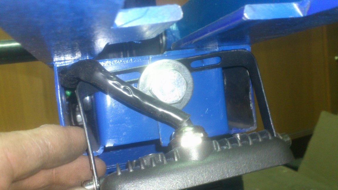
Turning on / off the machine is done by the "fungal" button in the center of the front of the table:
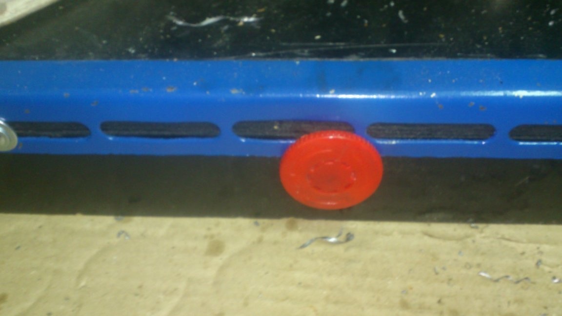
The button is rotary. That is, in order to turn on the machine, it is necessary to turn the "fungus" clockwise. (Which excludes accidental clicking). But to turn off, just click on it.
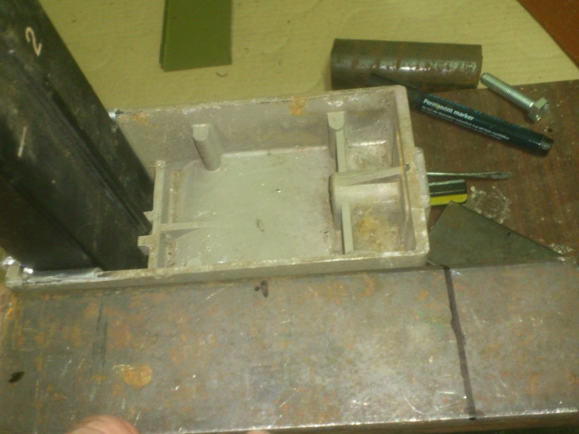
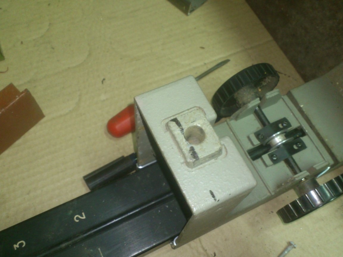
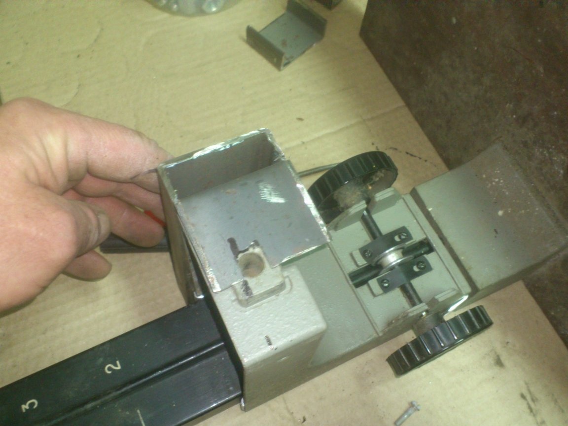
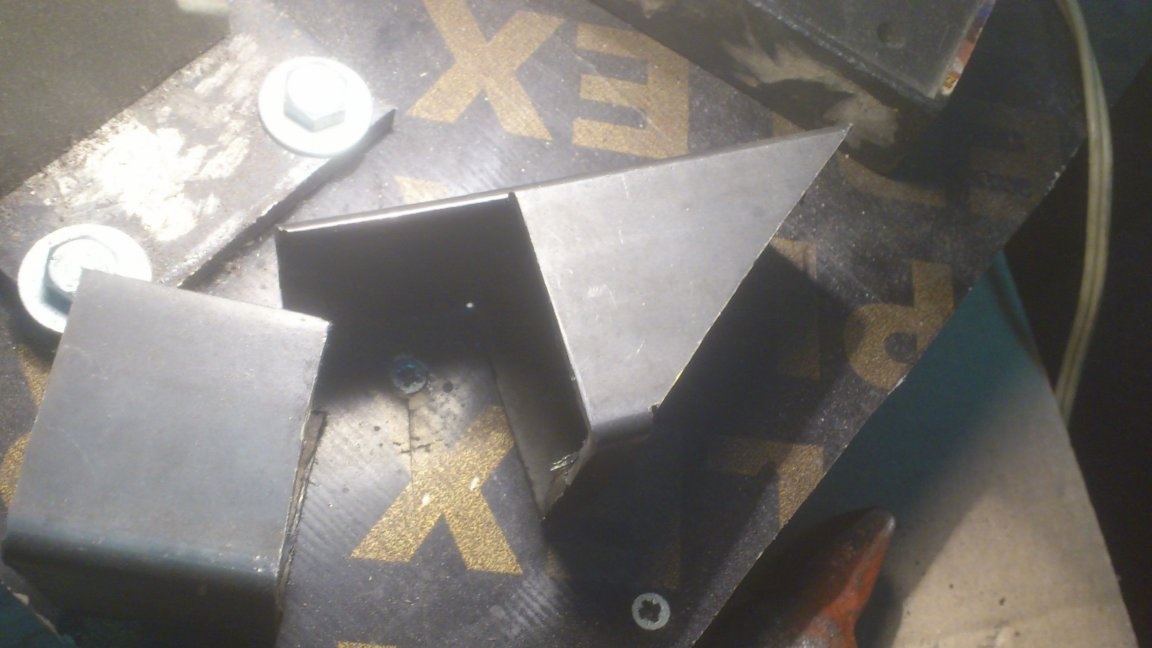
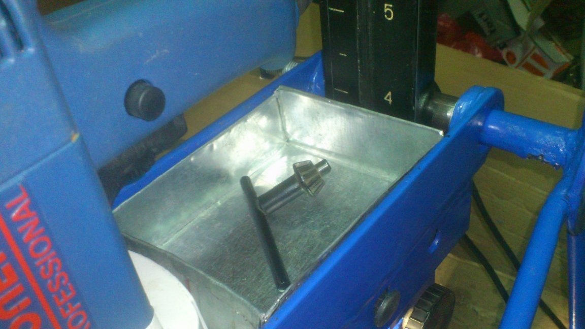
I also decided to use the space between the mixer and the boom. Bearing corners formed there a kind of box ... Only without a bottom))))
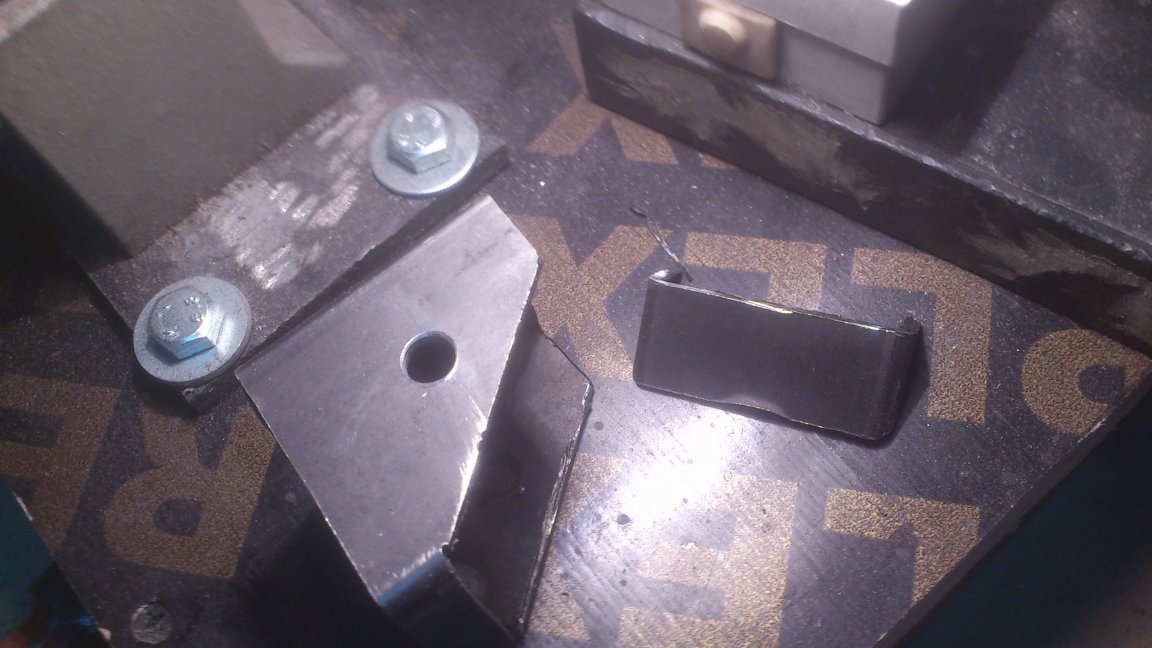
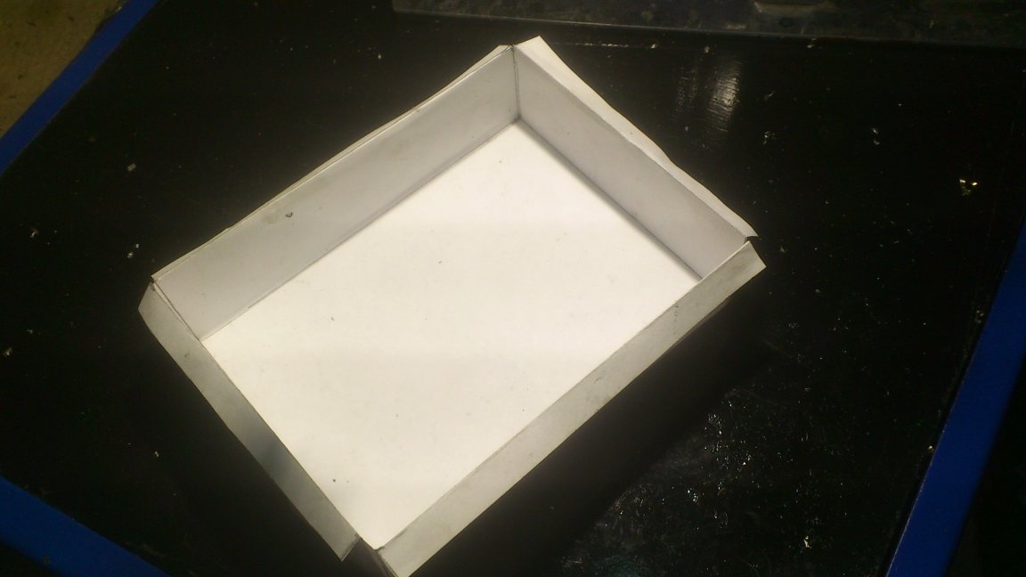
That's where I decided to make a box. First made a prototype of paper:
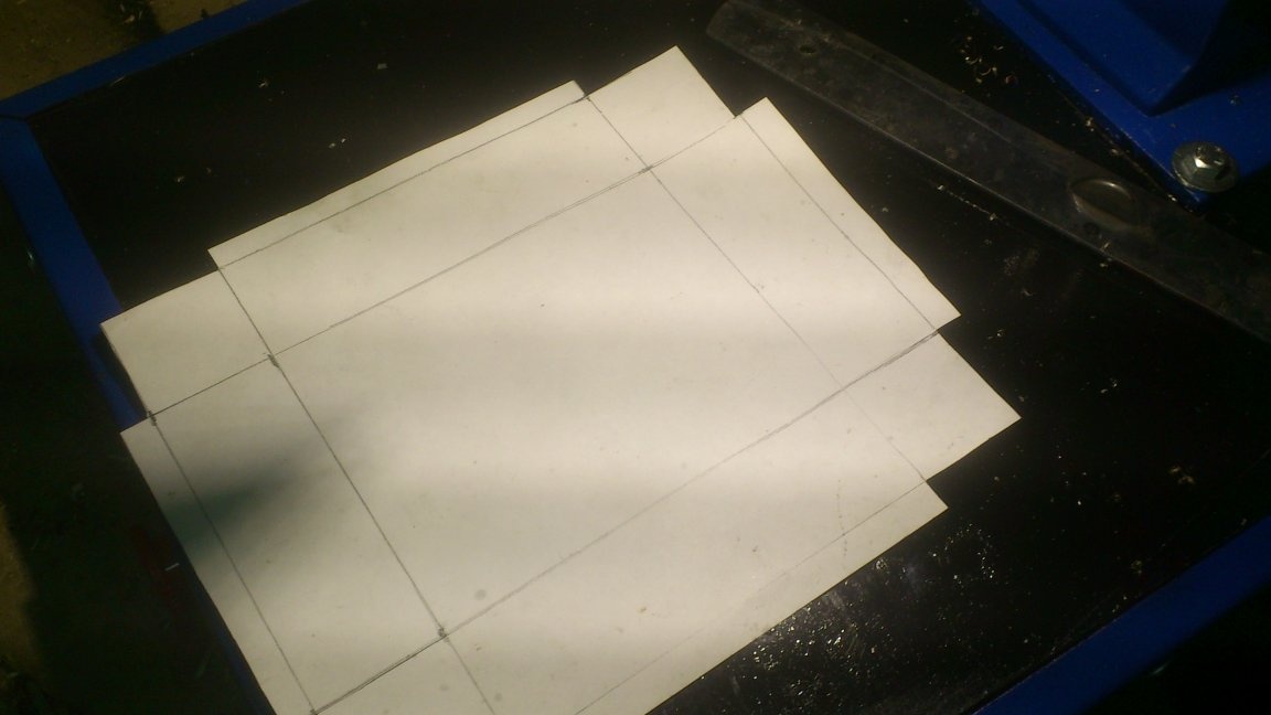
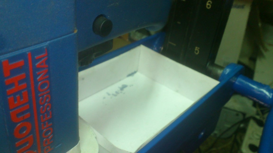
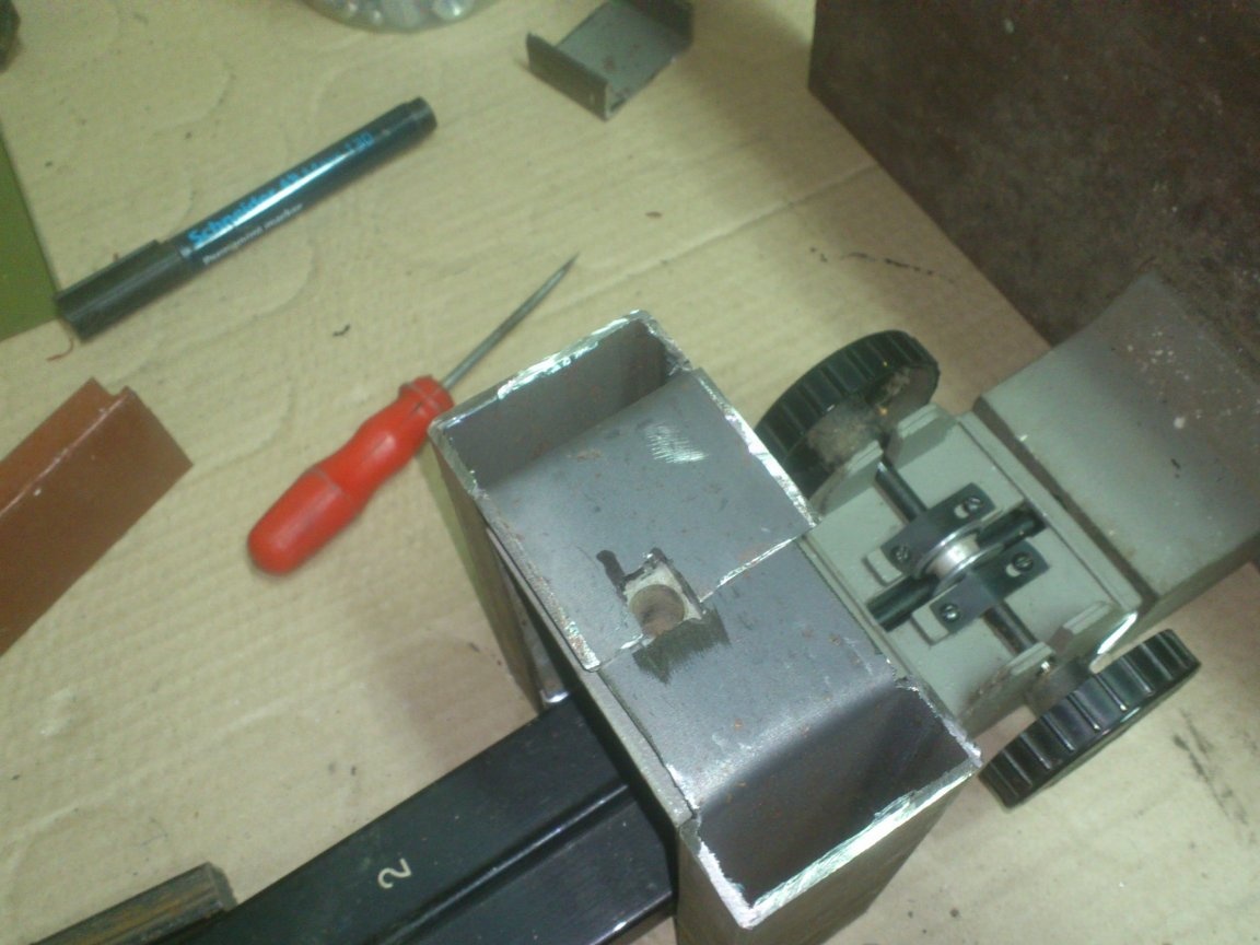
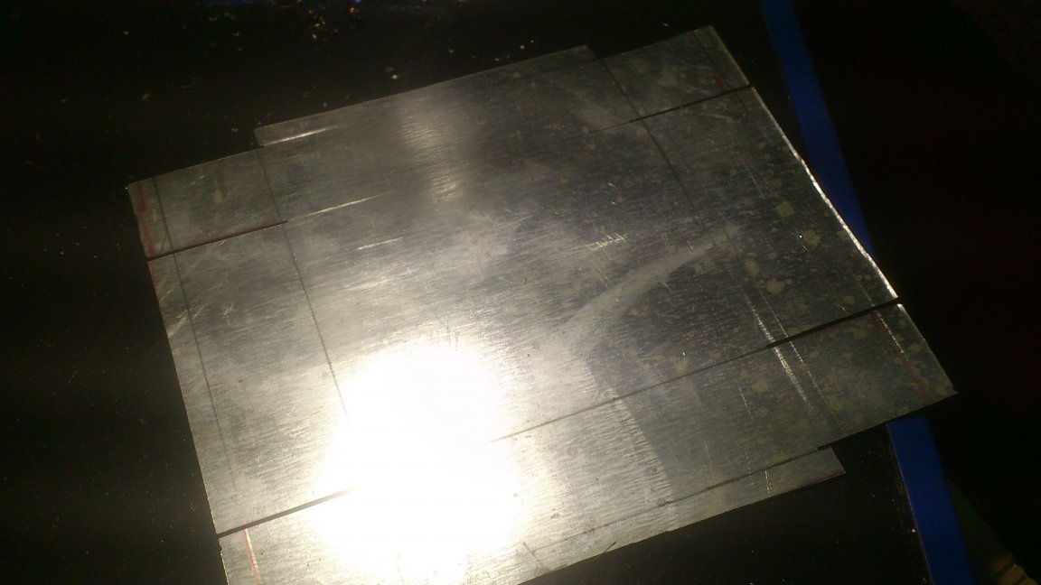
Then, according to this template, he made a box from a piece of roofing sheet metal:
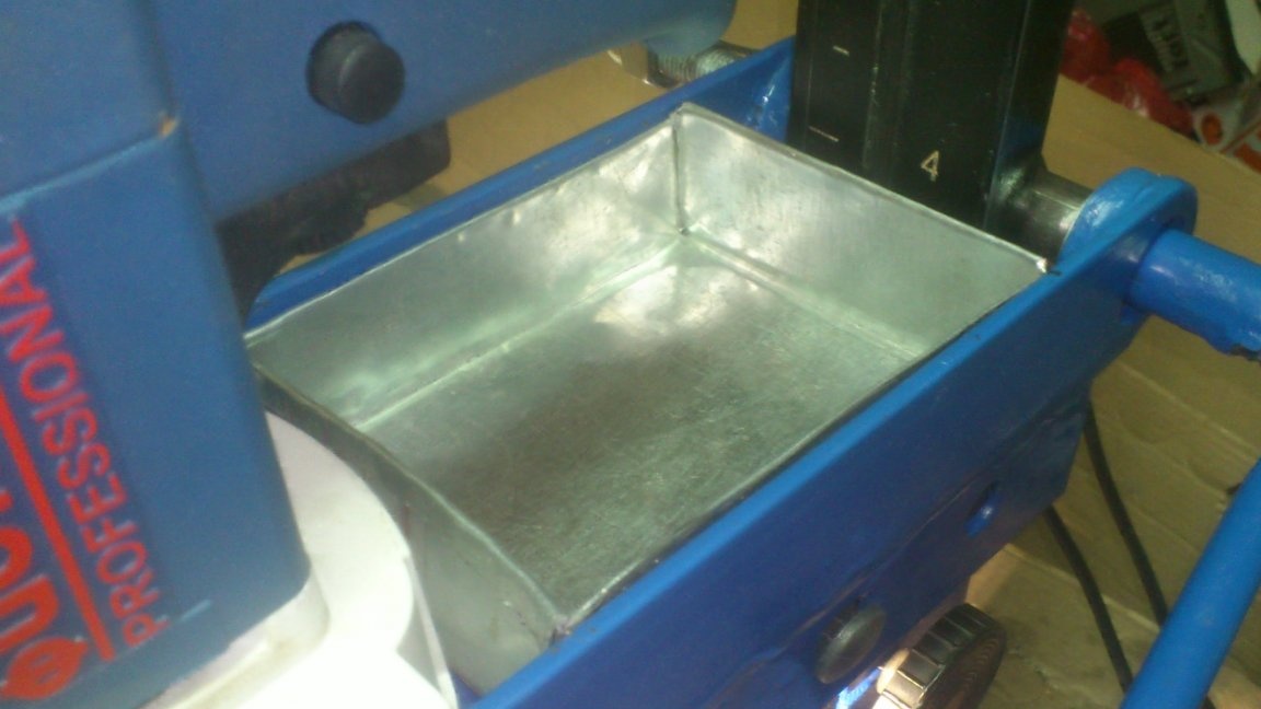
To the bottom of the box stuck magnets that were available:
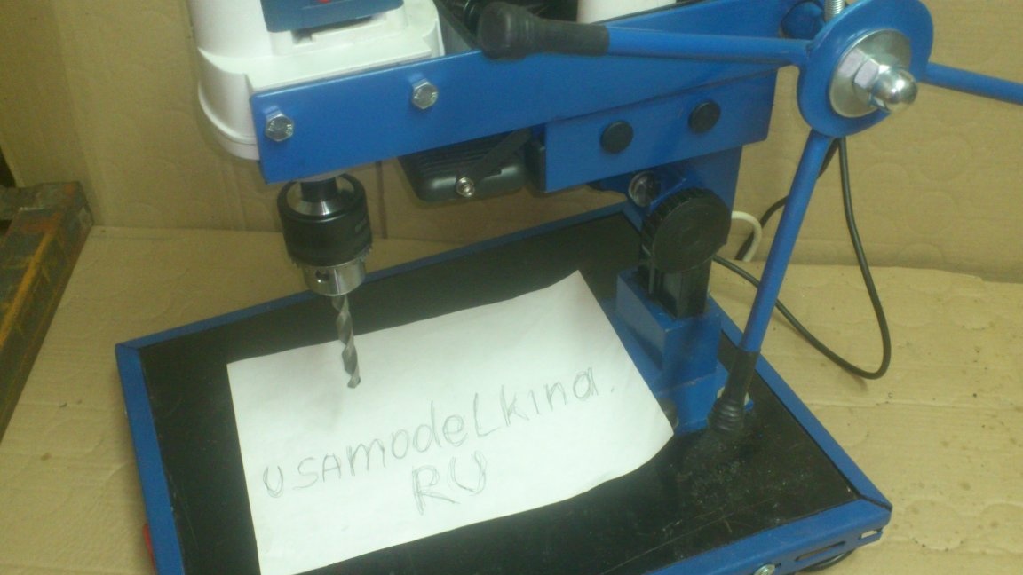
Now the cartridge key will not strum from vibration)))):
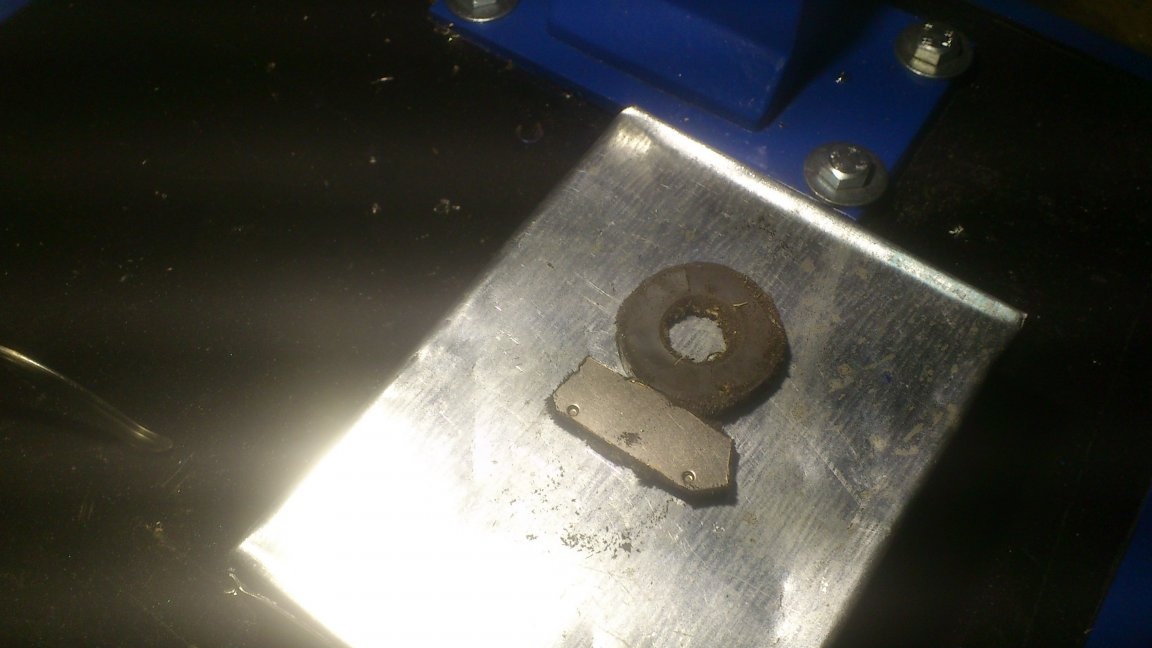
Oiler is also a necessary attribute of a drilling machine. Only now ... I have it plastic:
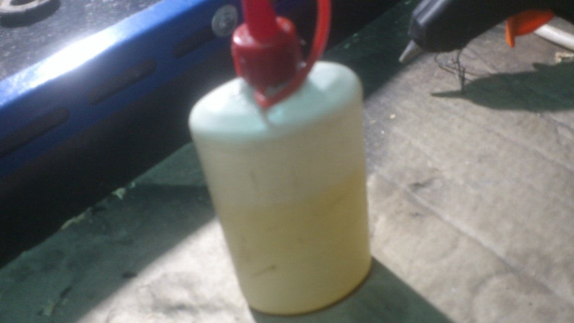
But I found a way out - having thoroughly degreased it, glued a large washer with hot glue to the bottom of the oiler.
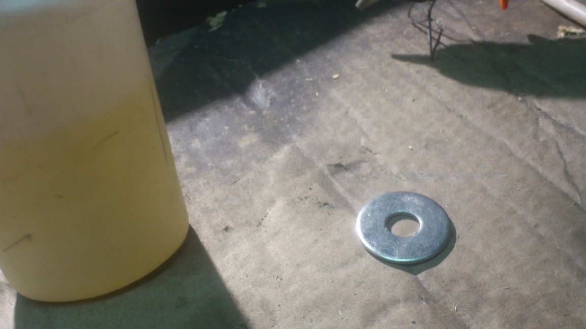
Now she can stand tight in the machine box, sticking to the bottom.
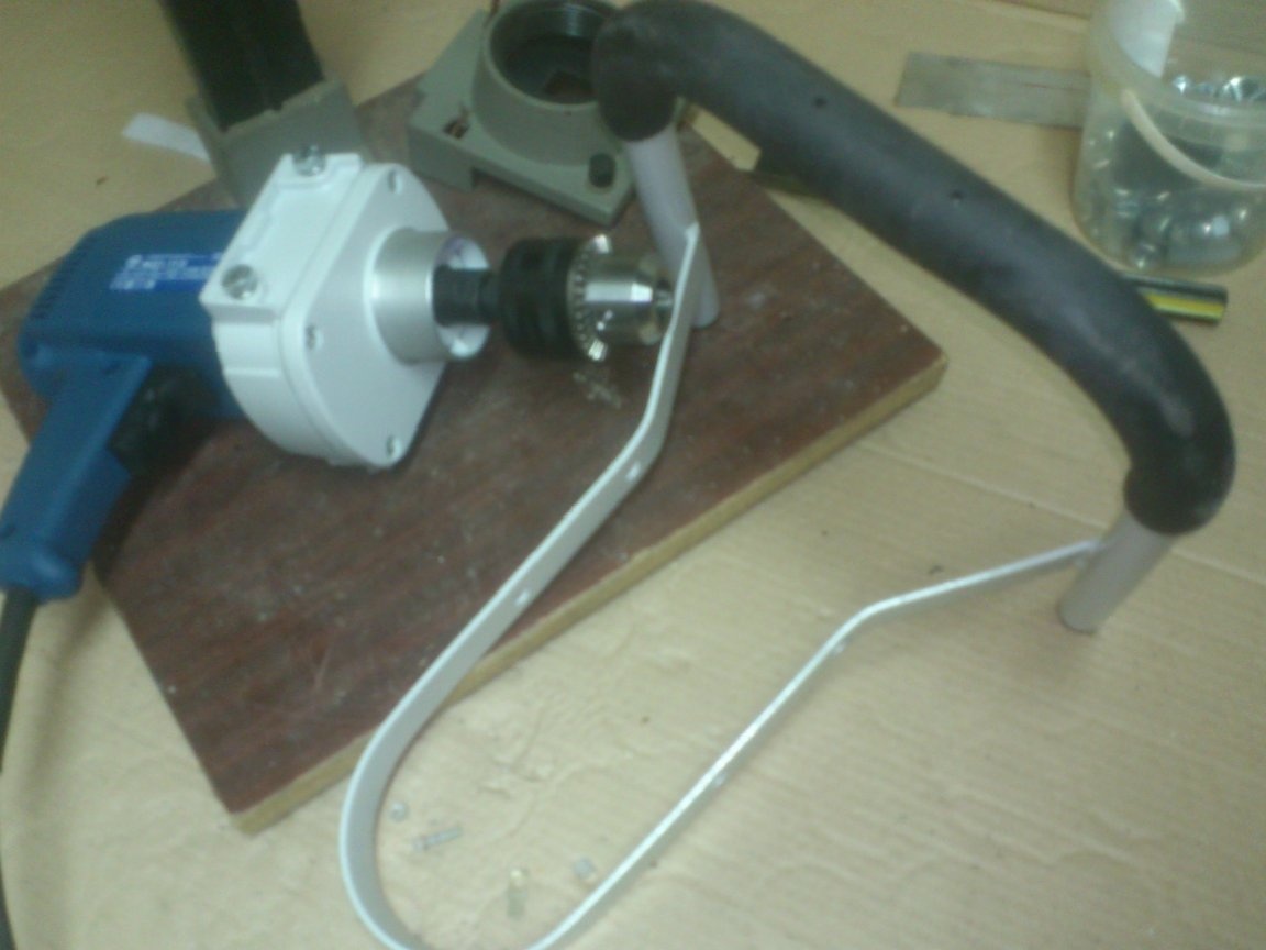
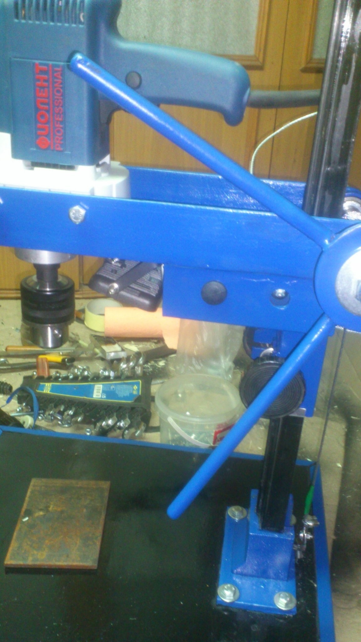
Here is a machine I got. In order to "bring out the perpendicular", I installed a straight bar in the cartridge, and, applying a square to it, put washers under the bolts of the rack to the table. There are four of them in every corner. This allowed me to accurately achieve a right angle between the drill and the table in all planes.
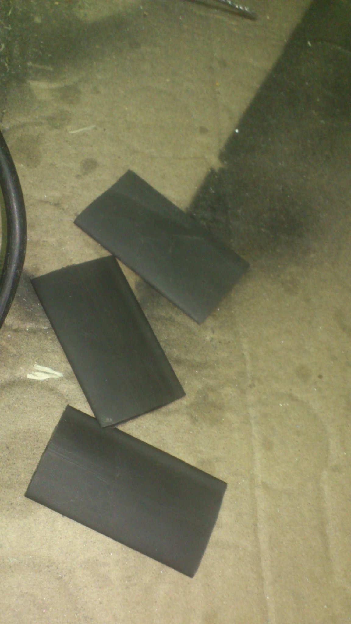
With such powerful loads, serious backlash was revealed. I dealt with them by placing aluminum corners in the back of the carriage:
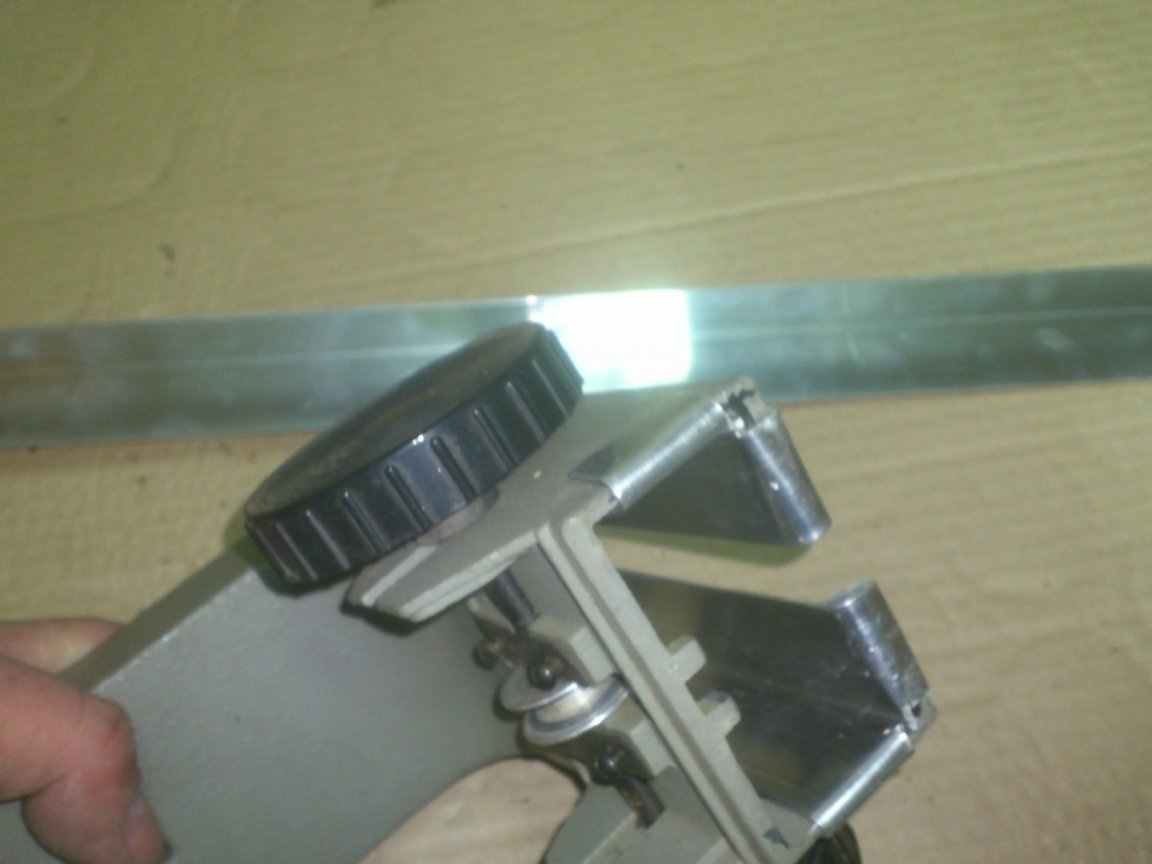
And in the front part there are fluoroplastic bands. (I didn’t take a picture. And now they are no longer visible))). At the same time, he made it so tightly that he had to wear the carriage on the bar with the help of a press, silicone grease. After I put on and assembled the elevator mechanism, I developed it by driving up and down.
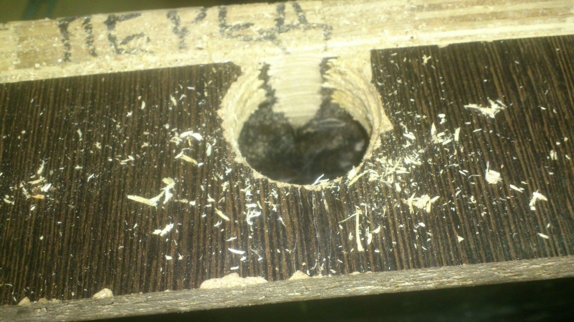
Tests have shown that machine power is excessive. He easily drills thick metal with a drill of 16 mm (!!!), even if you turn off the speed by half with a PWM regulator. With a strong clamp, the speed does not change.
At the same time, such a long chip comes out from under the drill:
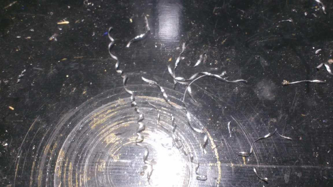
I think it will be necessary to think about a home-made coordinate table with a vise for him - as I already said, the channel was pulled out of my hands during the tests. And then, if the coordinate table is strong enough, it will be possible to use it as a milling one. Indeed, the spindle bearings of the mixer are designed for very significant radial loads.