Hello, dear visitors of the site.
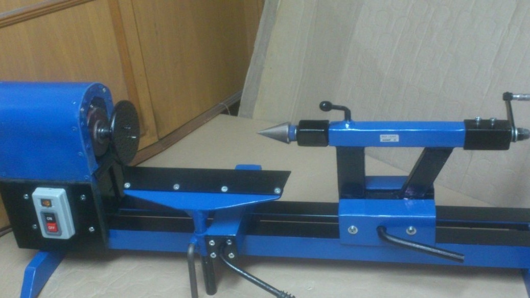
Today I want to show you my next homemade product. This is a wood lathe.
I have long had the idea to assemble a small wood lathe. Why do I need him? ... That I did not know! )))
I even jokingly asked friends to come up with an answer to this question, because I want to do it, and why I need it - I can not formulate it! ))).
And then my daughter asked me: "Dad. And how do you grind figures from a tree? For example, I saw wooden eggs! Easter is approaching. I would paint them and I could give them to everyone!" (My daughter is an adult. I have a rather talented artist. We love the holidays and always decorate the apartment and receive guests. Simply, we have many friends. Guests come to us very often and we are happy to see everyone.).
"Here it is!!" - I thought! ))). Now, I’ll definitely do the machine !!!

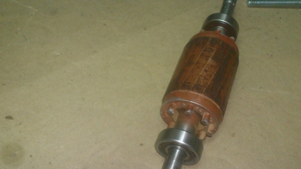
I went over the engines that I have ... The most suitable were the motor from the old washing machine (activator, not automatic), and the motor from Hydrophore. I discarded the motor from the washer because of less power, and (for some reason) large sizes. (??). At the same time, his anchor was not heavier than the anchor of the “gyrophoric” motor, which indicated that his torque was not greater .... (I disassembled both to visually check the condition and find out the sizes of the bearings).
The Hydrophoric had an uncomfortable shape for the front cover, and, most importantly, it had no paws. His mount was flanged, and behind was one "leg-support" ...
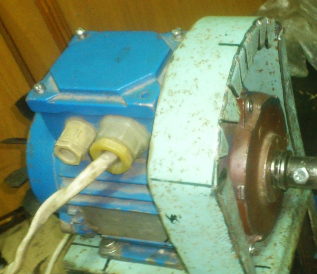
And then I noticed that the anchor and body of this motor are very similar to the corresponding parts of the other from which I had made a polishing machine. In its past life, this machine was also a water pump, only an ordinary one, and not as part of an autonomous water supply station.
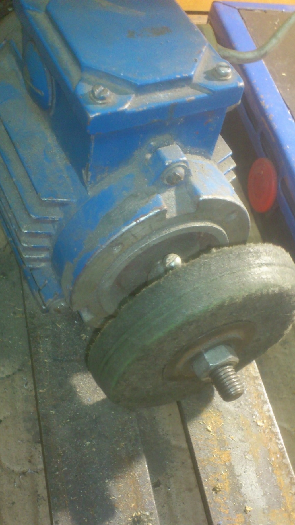
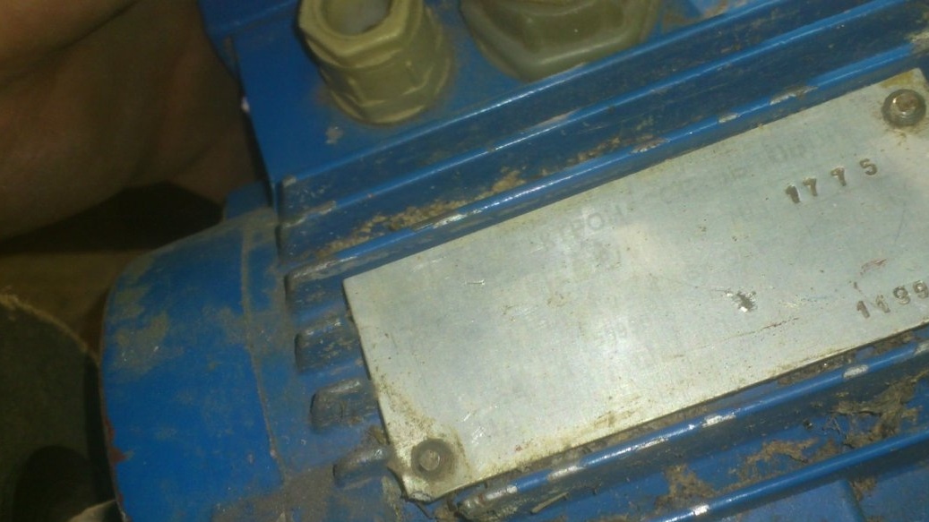
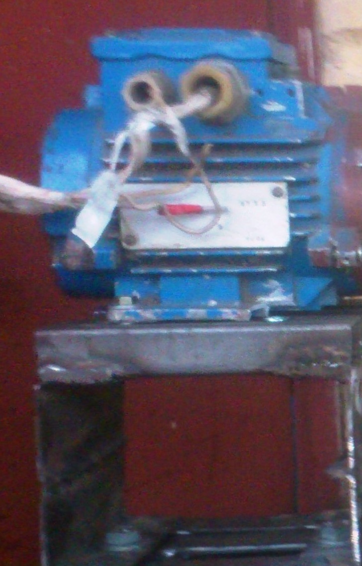
On this motor, the nameplate has long been obliterated and I did not know its characteristics:
But, having examined it too, I was convinced that the motors are identical. And they differ only in front covers and the presence of a mounting pad on the second case. (The first one has a "vestigial" in this place))) Apparently, a trace from the plug in the mold for casting))).
So I found out that both of these engines have a power of 0.45 kW. Turnovers are not known - on the nameplate of "Hydrophore" are indicated instead liters per minute)))). But, visually, I realized that they are in the region of more than a thousand.)))
And I decided to use the motor from the machine, and then adapt the polishing wheel to the “hydrophore” motor .... Or, to the motor from the washing machine ... (This, however, is unlikely. Because, contrary to frequent misconceptions, a large polishing wheel is needed power than for emery - the clamp is much stronger and larger. And the motor from the washer is weaker - it seems 340 watts.)
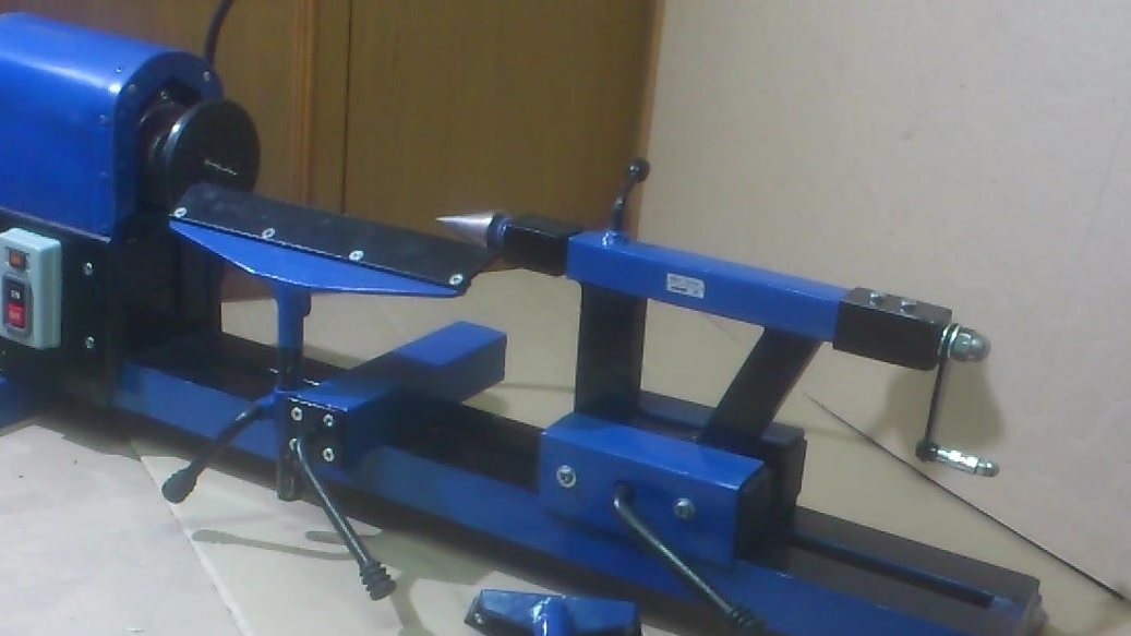
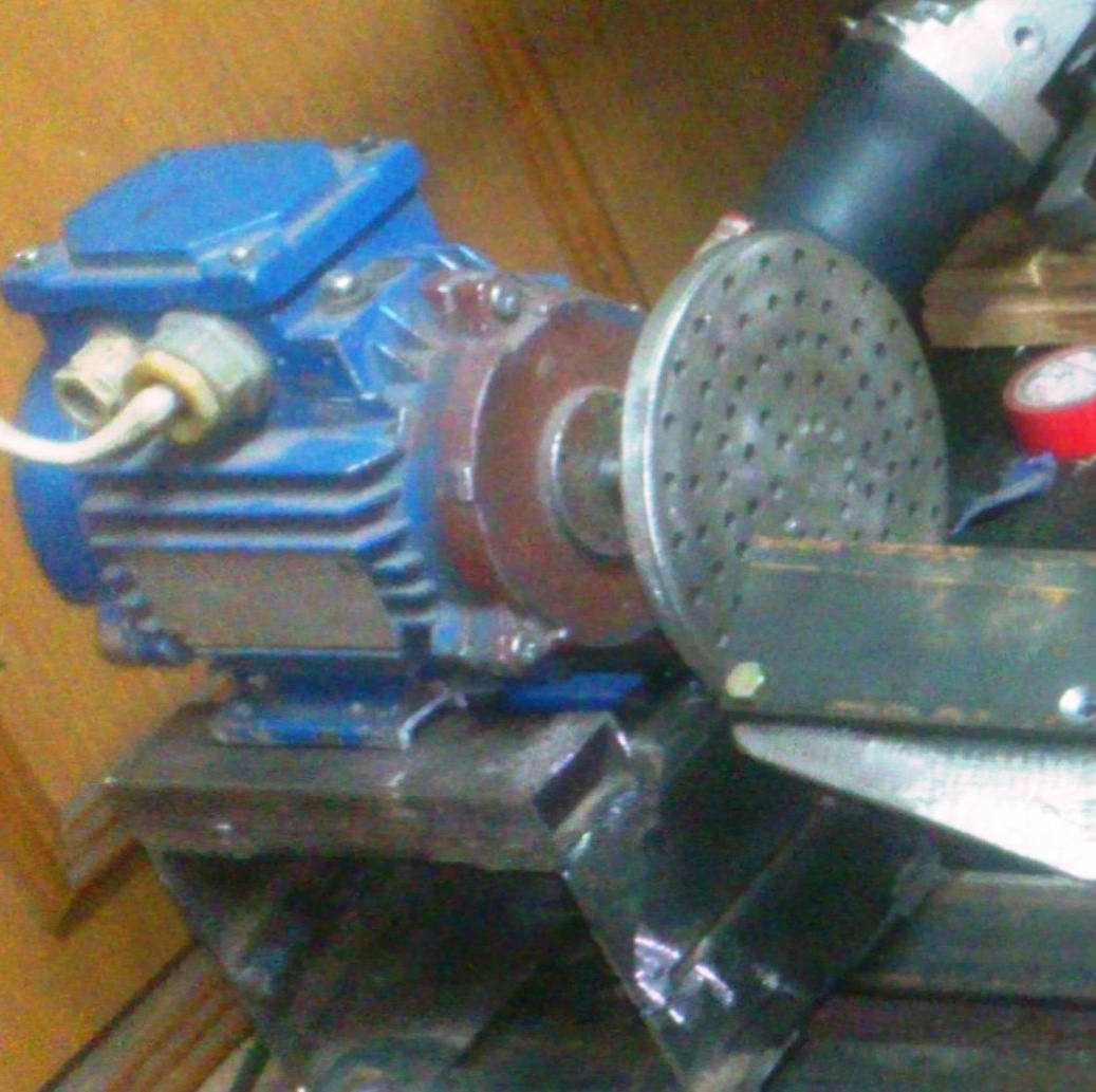
So, I eventually assembled the machine.
Whoever is not interested in a detailed description of its manufacture, he can see a brief overview in this video:
And here is what I needed for this:
1. Asynchronous electric motor, power 0.45 kW.
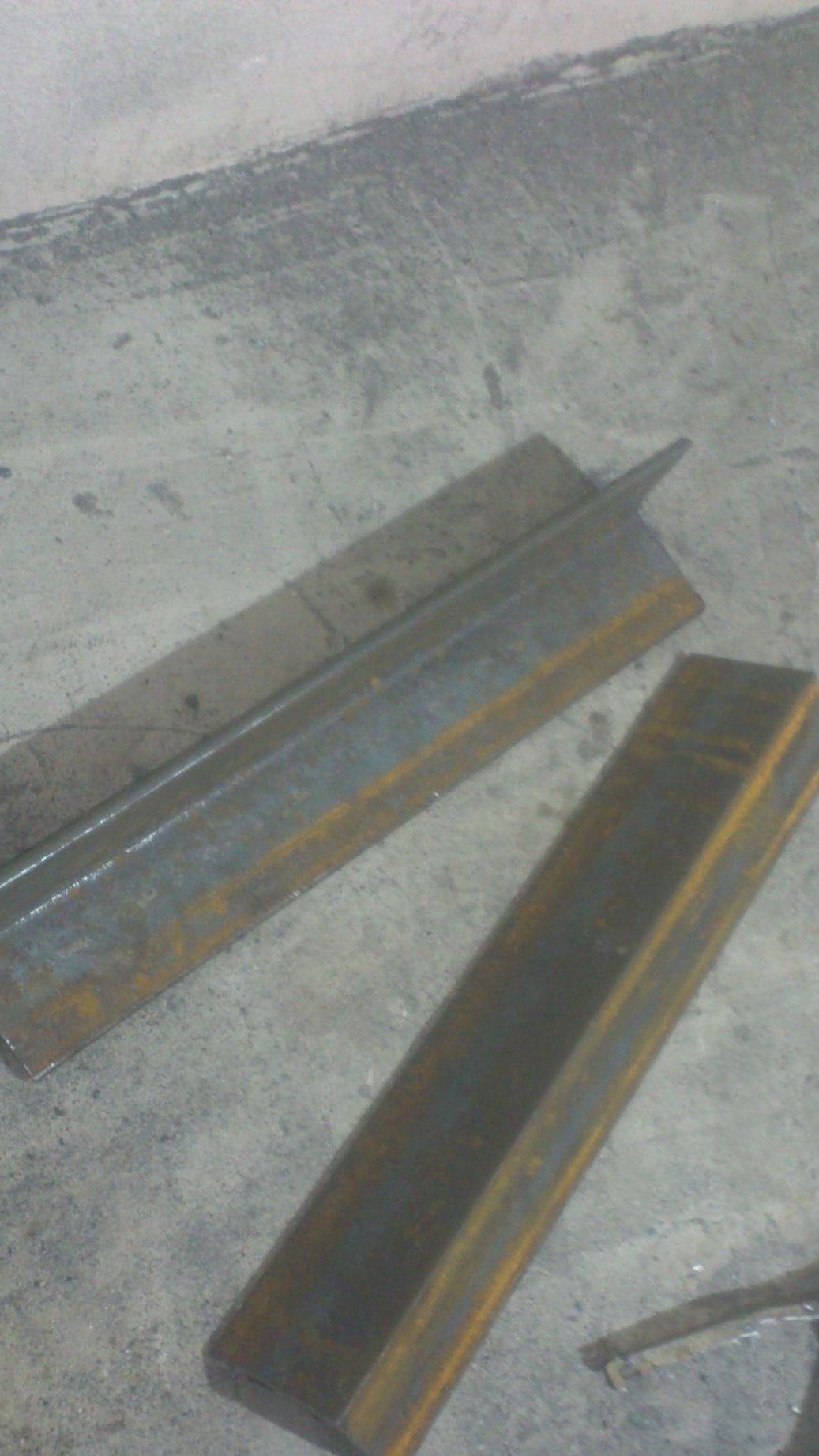
2. Various metal rolling (Basically - scraps of a corner on 50 on 50, strips, water and profile pipes of various section.)
3. Construction plumb.
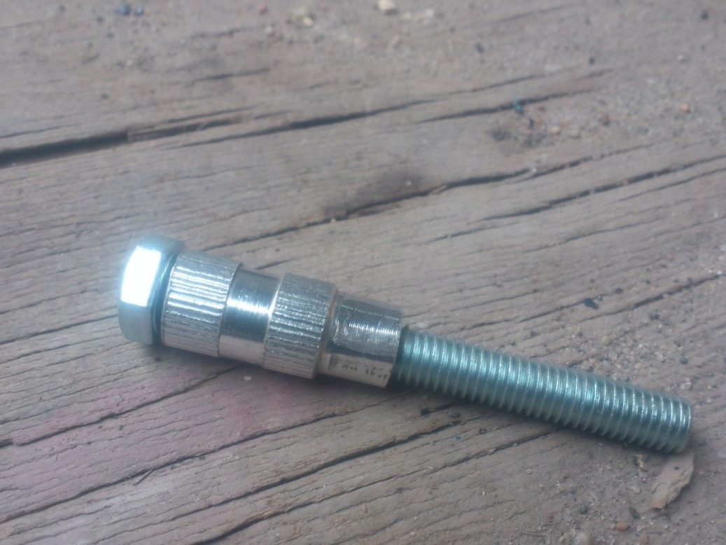
4. Hairpin M14.
5. Hardware (bolts, screws, nuts, washers of various sizes.)
6. Electrical components (toggle switch, switches, wires, etc.)
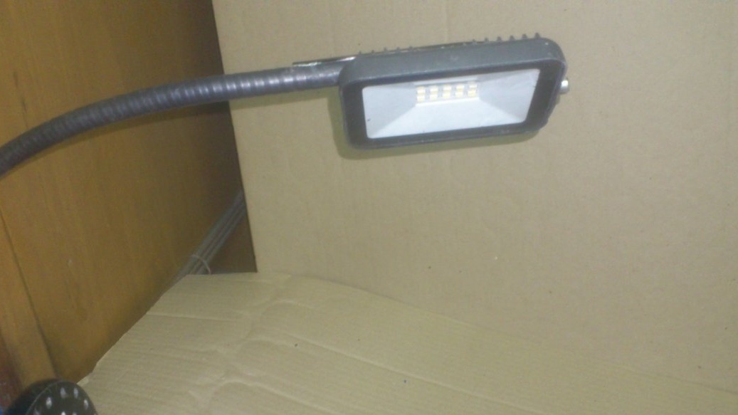
7. Diode spotlight 10 W (for illumination).
8. Thick metal 10 mm (cut 150 to 150 mm)
9. Replaceable spikes for sports shoes.
10. Two thrust bearings, one radial and one angular contact bearing.
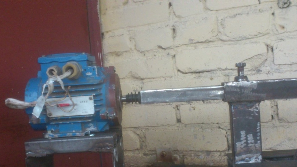
During the time when, as described above, I was engaged in the selection of a motor, I made a bed and a handicraft, which I described in detail here in this article.
But, in addition to these details, the machine also needs front and rear headstock.
The front one, as a separate element of the transmission, I decided not to do, but to get by with direct drive. (This is when the motor shaft is the machine spindle). Of course, it is better to make a step gear, then you can adjust the speed and torque. But I sacrificed these advantages in favor of the simplicity and compactness of the design. After all, in fact, I am making a "toy with increased functionality", and not a full-fledged machine. I do not need a full-fledged one. I am not going to work on it regularly. Therefore, I need one that fits on a shelf and will stand there for months, and maybe for years.))). And when you need it, I'll take it off, bring it into the trunk of the car and go to the country to sharpen it.)))) ... Something needs to be done, similar in concept to mine pipe bender.. That is, quite light and compact.
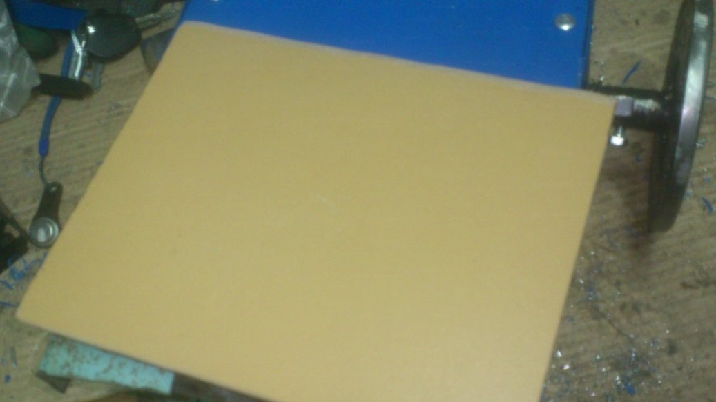
Having decided on the dimensions of the arm frame, I decided, just in case, to raise the axis of the machine above it by 150 mm. (Above the bed of the handcuff). You never know ... Suddenly, someday I want to grind a plate.
And the second point was that I did not want to “tie” the entire machine to one specific motor. (Suddenly, this one will be damaged! Suddenly I will find the best one in terms of characteristics, and it will be of a larger diameter. After all, then, in addition to the front one, you will have to redo the tailstock ... (Read: make a new machine !!).
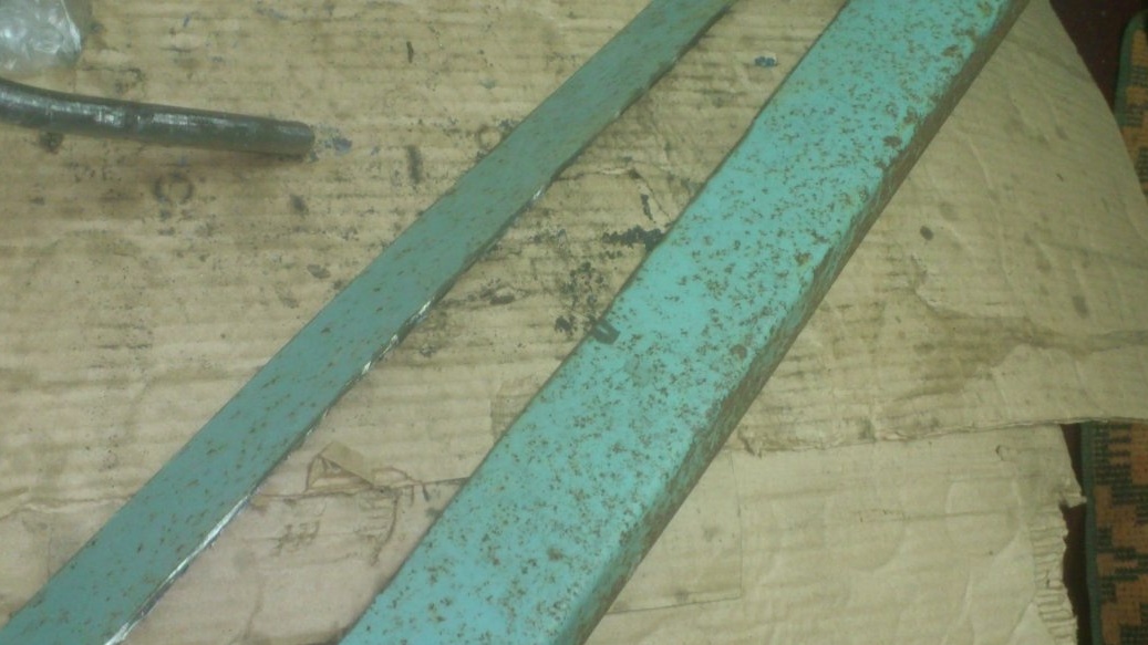
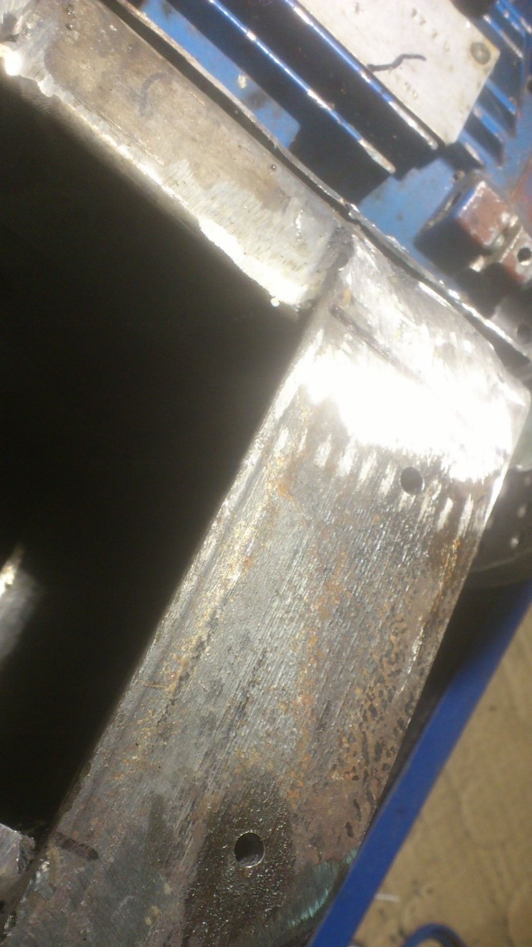
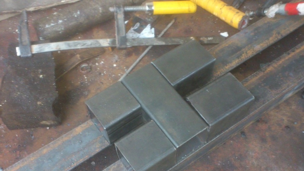
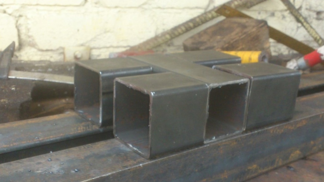
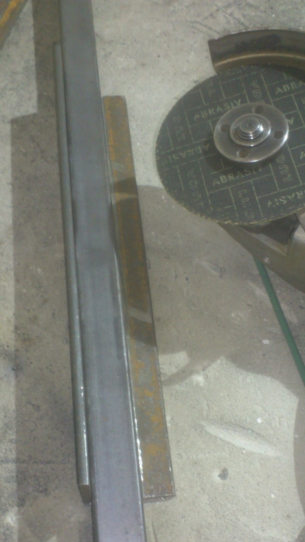
So I made a tall stand for the engine. First, "for trying on" I decided to weld it "fast" from the scraps of profile pipes 50 to 50.
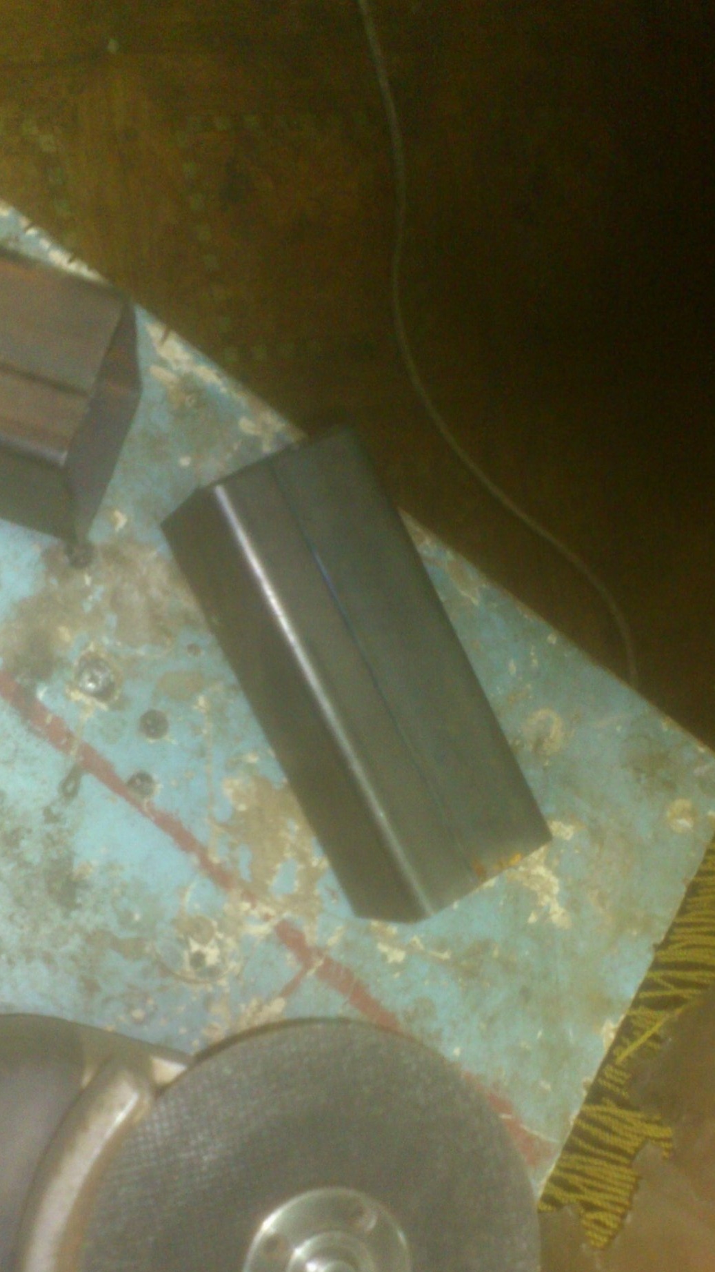
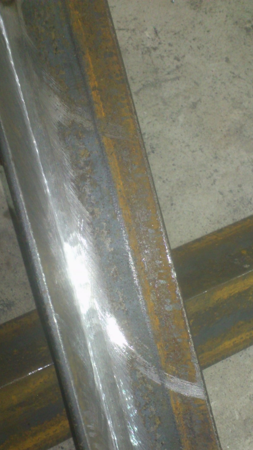
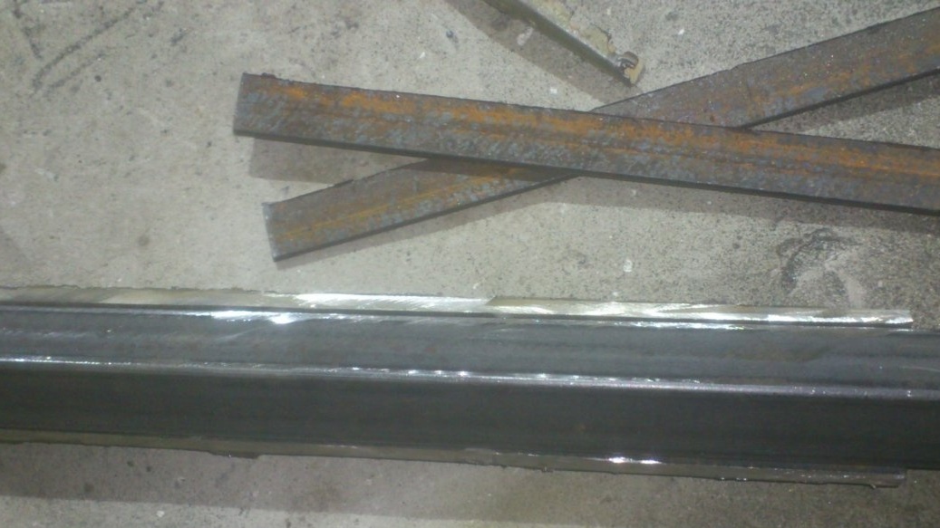
I cut them along:
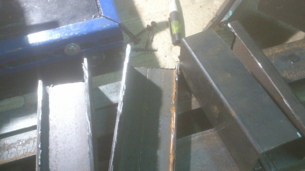
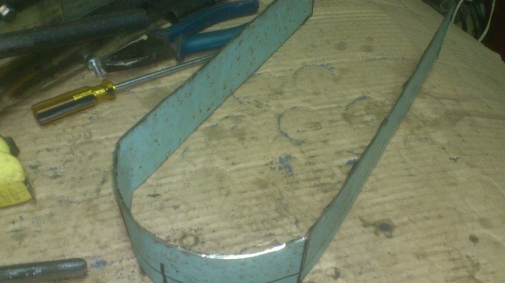
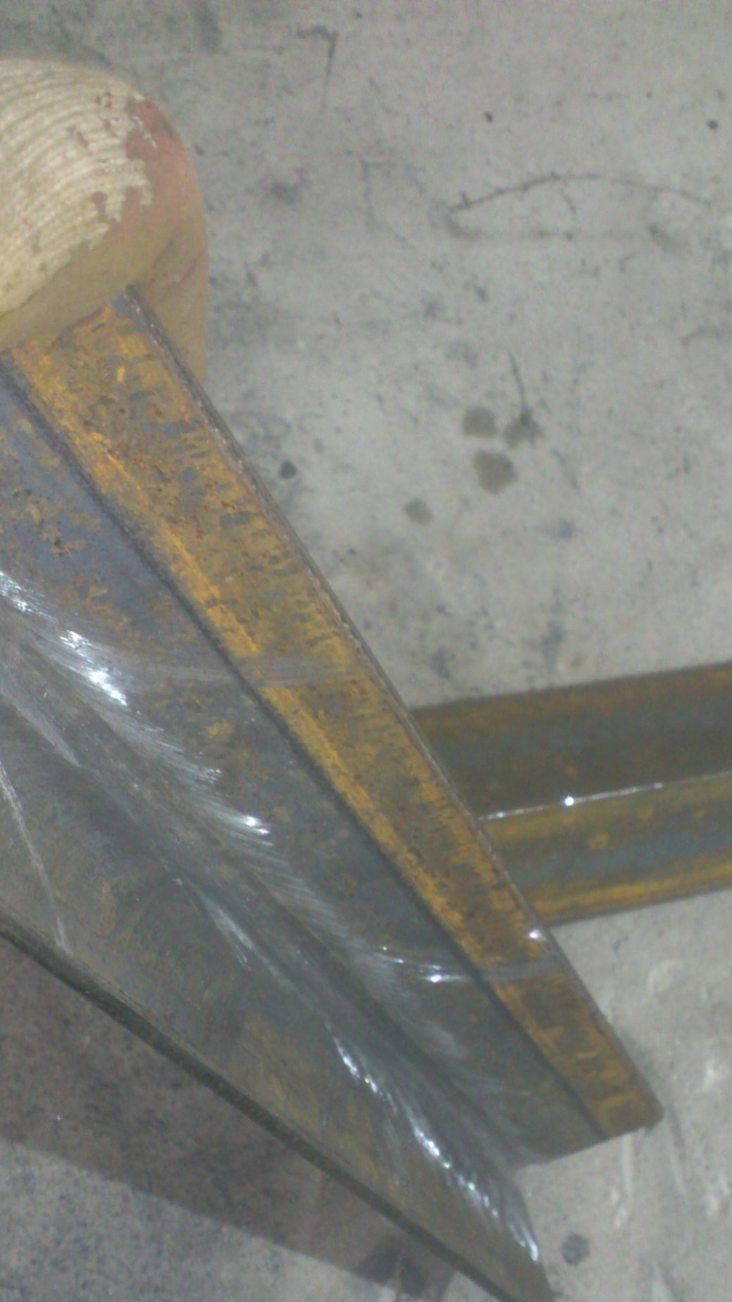
Then he cooked in pairs, and made the front and back walls of the stand out of them:
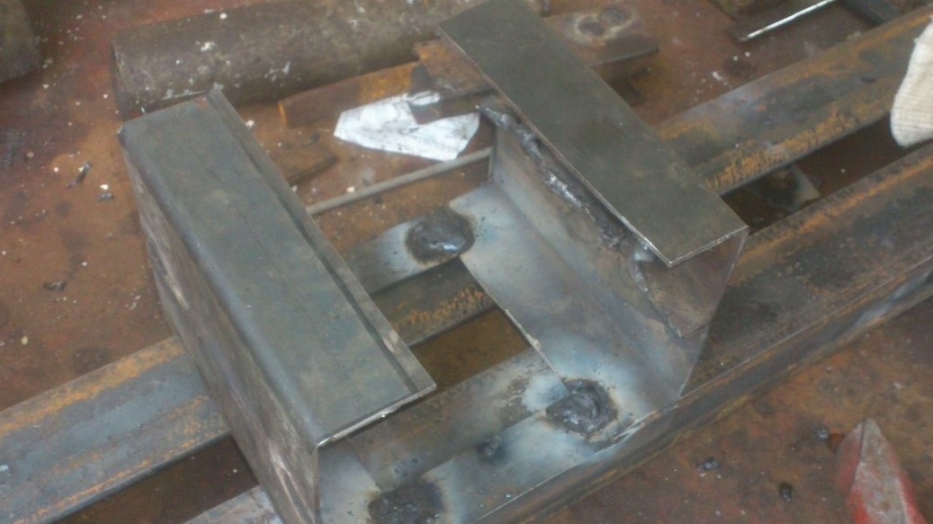
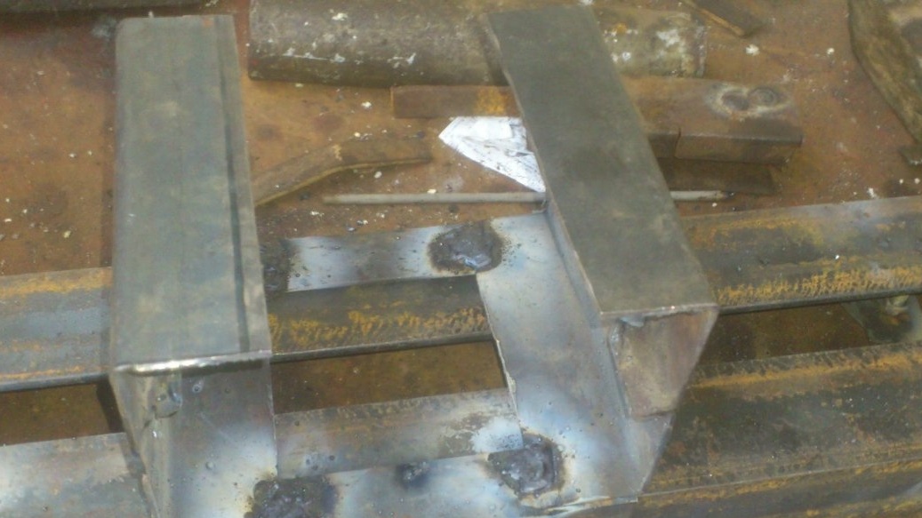
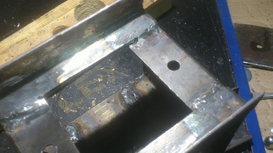
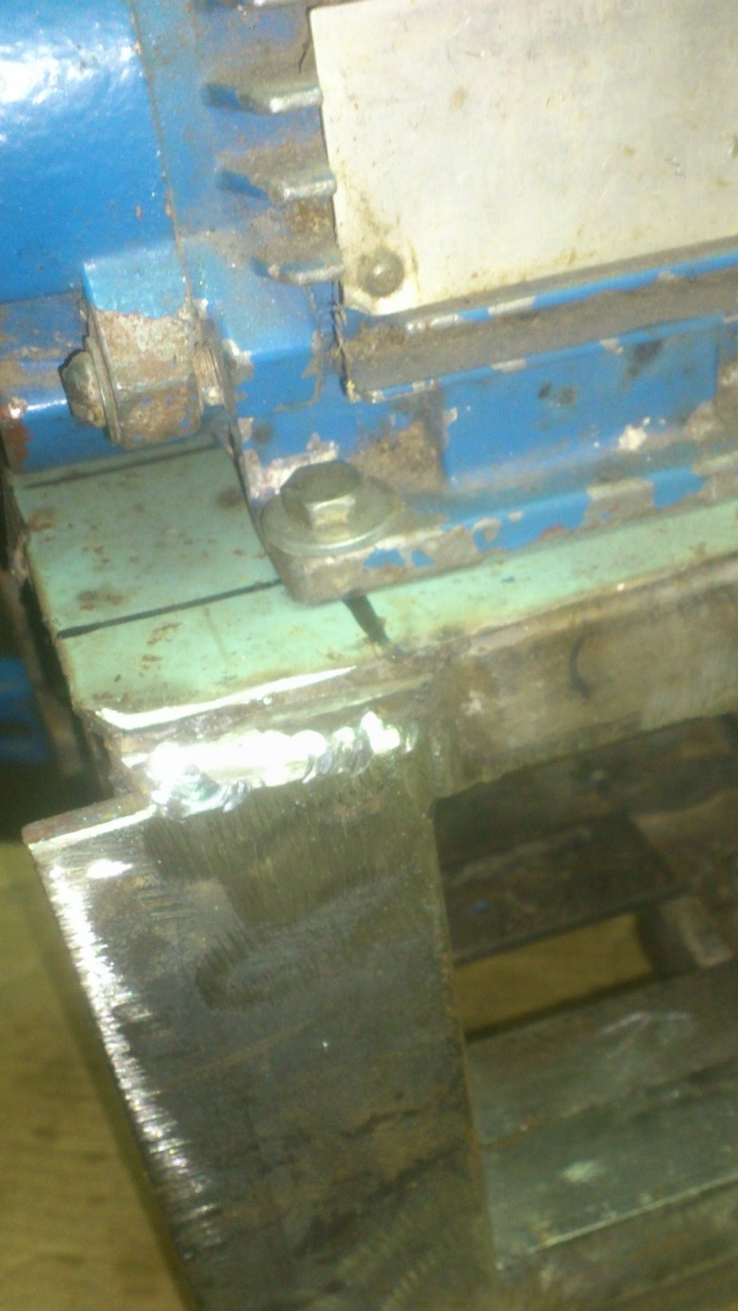
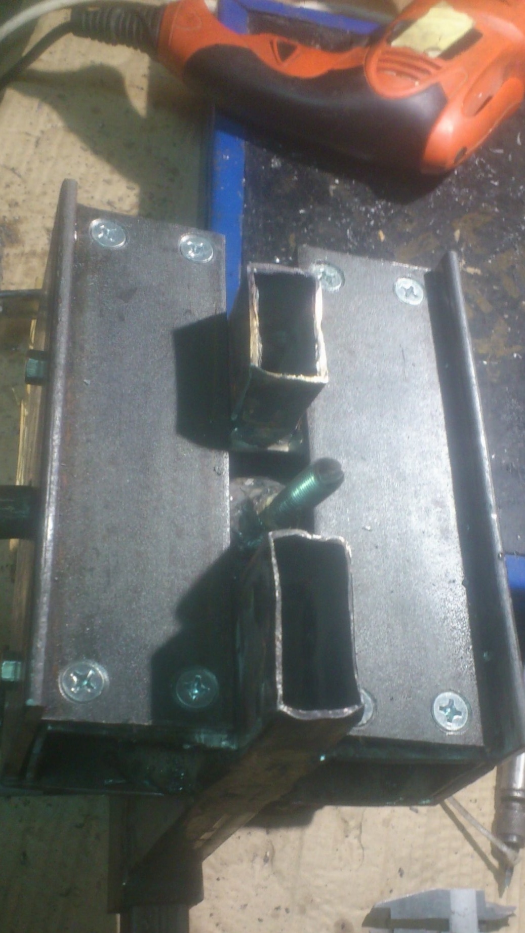
I decided to make the headstock removable. therefore, I did not weld the racks to the bed, but placed them on the “slide” from the corner 25 to 25, using the bed as a template:

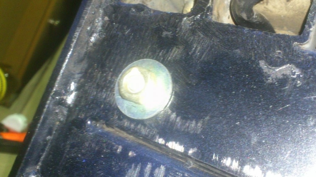
For mounting, I drilled two holes in the bottom. M10 bolts will be inserted and welded into them later. With their help, wearing wide washers from below, the entire headstock can be tightly drawn to the bed.
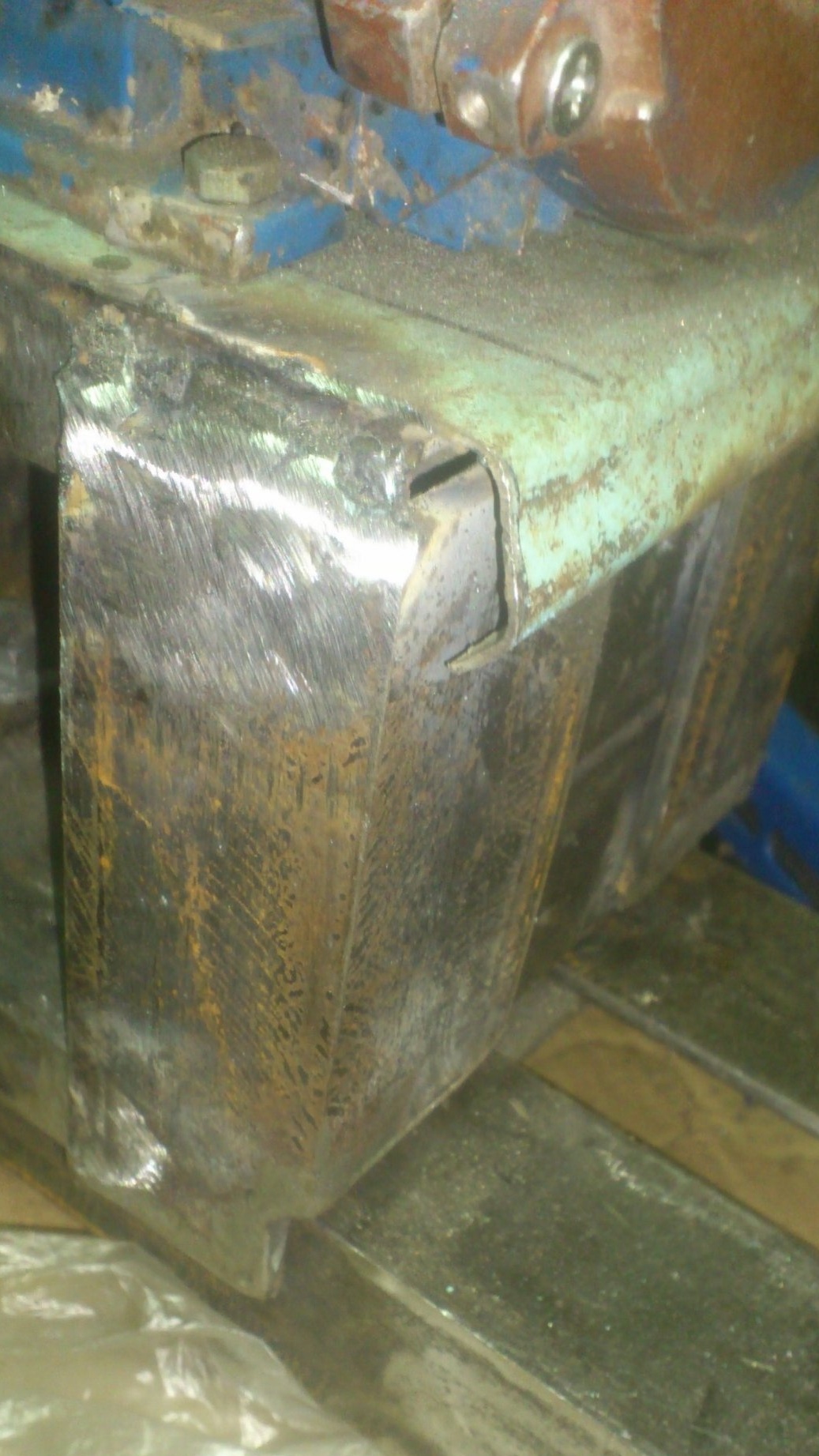
And in the upper part, I welded two longitudinal segments of the profile pipe 40 by 25 and drilled four holes for M6 threaded rivets in them.
Through their engine will be mounted on a stand:
Now let's deal directly with the spindle. For wood turning, various methods of fastening workpieces are used. The most common is the trident. The workpiece is clamped between it and the rotating center of the tailstock. In this case, the trident deeply "eats" into the end face of the workpiece and can rotate it. But this method is acceptable only when working with the tailstock. If the product involves the processing of the end (plate, glass, etc.), then the workpiece is mounted exclusively on the spindle. In this case, usually, the trident is removed, and, instead of it, a chuck or faceplate is installed, to which the workpiece is screwed.
Since I use direct drive, I initially decided to make the faceplate non-removable. And so, what is the reason ....
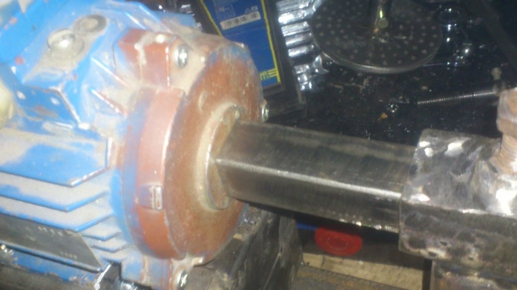
With direct drive, as already mentioned, the motor shaft is a spindle. When clamping a workpiece with the tailstock quill, a very large axial force will be applied to it !! Typically, electric motors are not designed for these loads, so conventional radial bearings are installed there.
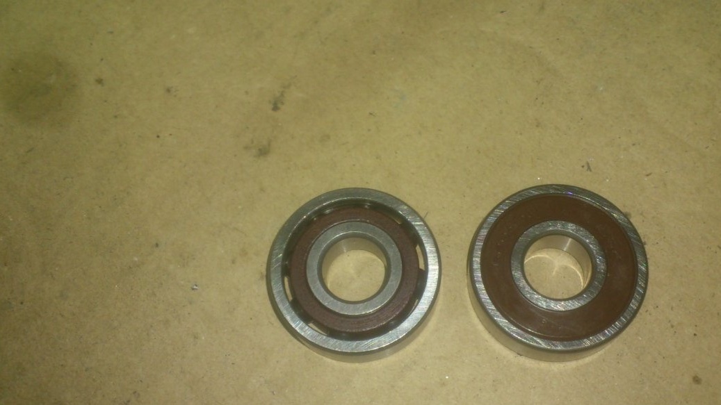
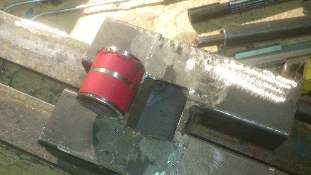
When I disassembled the motor, I found that it uses the usual "two-first" bearings. (According to the current classification - 6201).
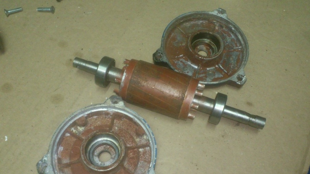
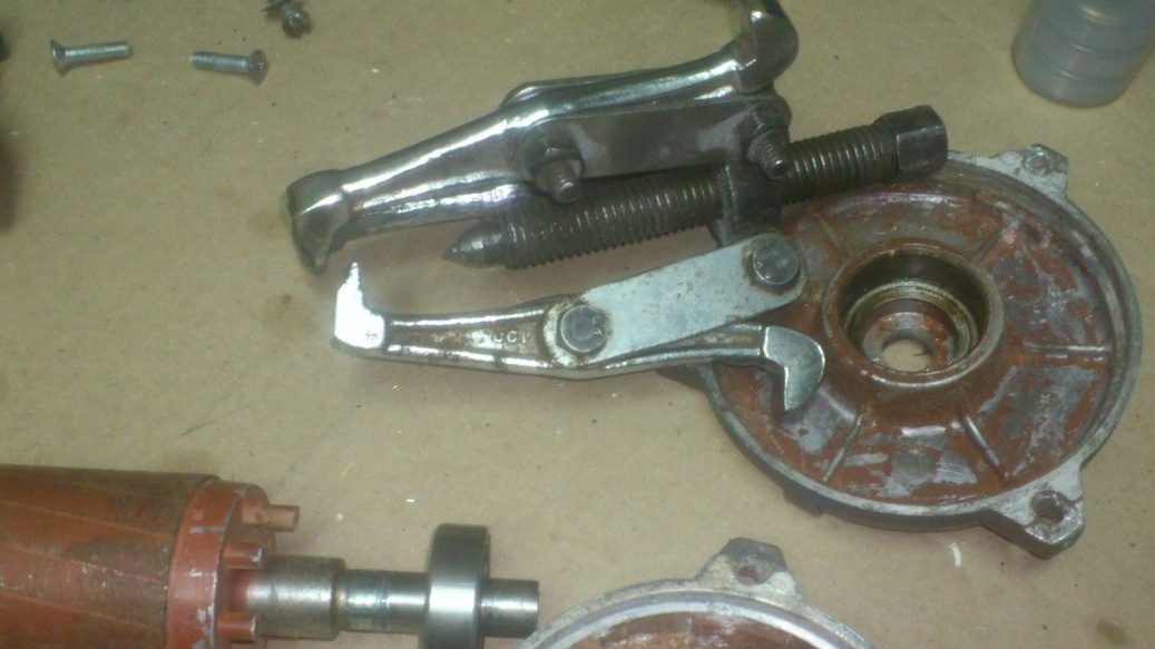
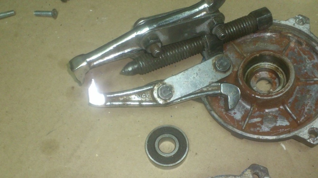
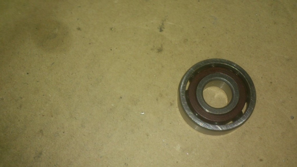
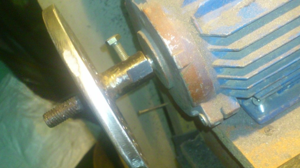
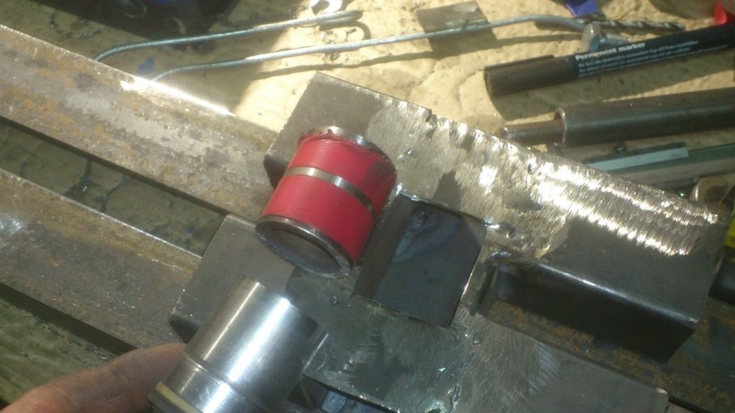
I dismantled them with a puller. And the rear one was replaced with a bearing of the same size (201), but in a radial-bearing design:
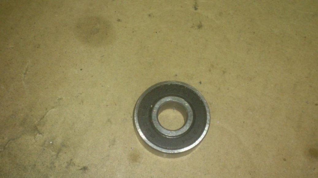
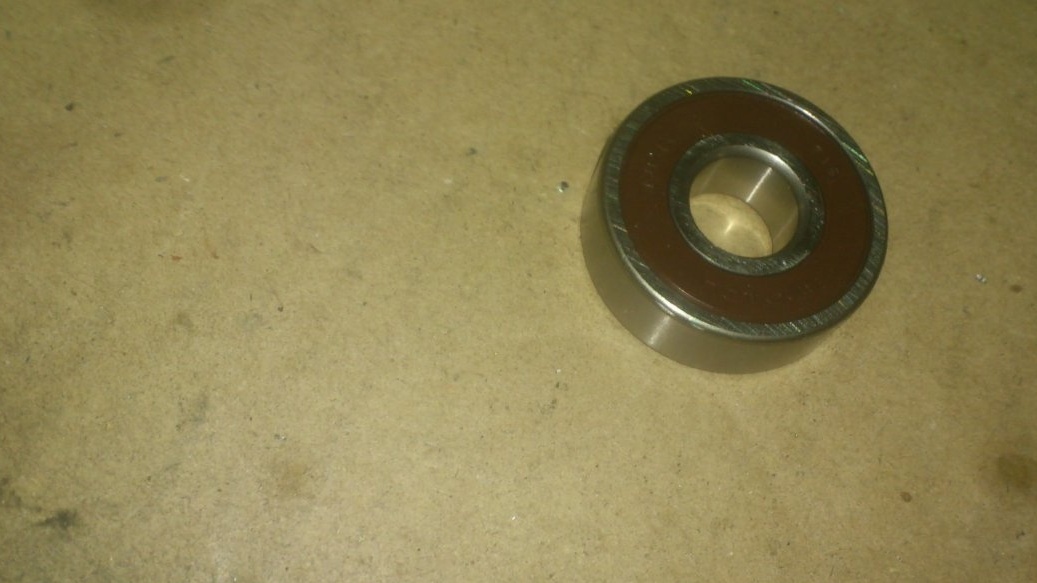
Putting the same in the front cover makes no sense - he has nothing to rest on. Therefore, forward I bought a radial one, only from a more eminent world manufacturer with the declared qualities, many times higher than those of the old one (I will not deal with advertising))))):
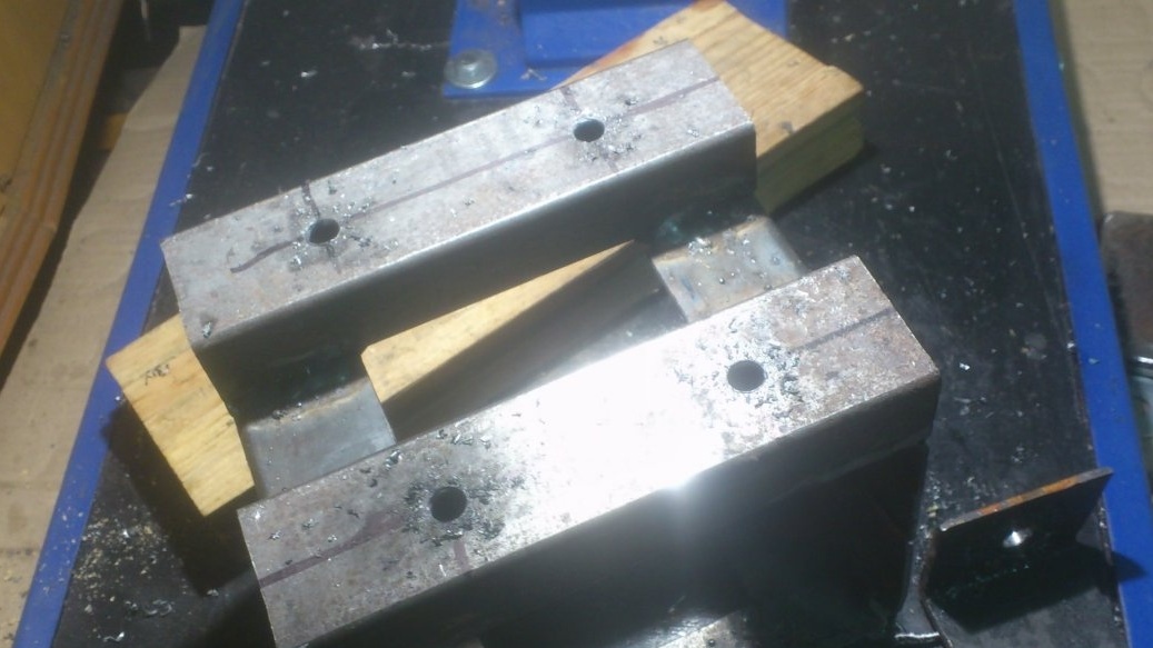
Motor covers also turned out to be different, albeit interchangeably. One - more "powerful" I installed it on the back:
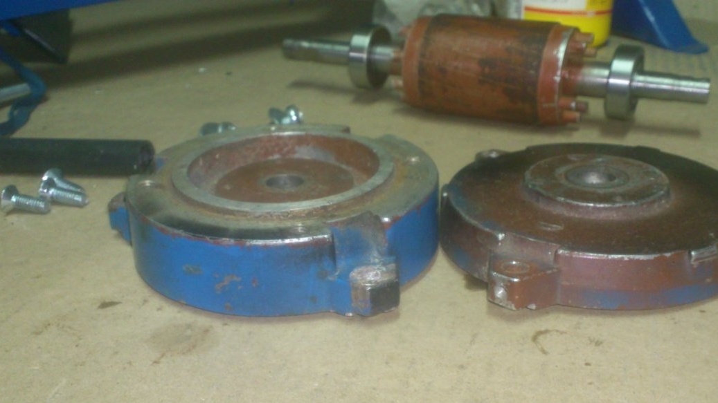
Since the compact (for its power and torque) dimensions of the motor are due to a rather "flimsy" housing, I decided to install yet another thrust bearing. As they say, God saves the safe. After all, there is a possibility that otherwise the back cover may not withstand and burst. Or, more likely, it can tear out the threads of the screws that secure it. In this model, the covers are not pulled together by studs, but are fastened separately by screws. The screws are screwed into the aluminum (!!!) thread.
Only place the thrust bearing in front of the front cover. That is, between her and the faceplate. That is why I would not want the faceplate to be removable.
As I mentioned, on this engine I had felt polishing wheels. On the one hand - a wide drum, on the other - a regular circle. That is, there were couplings for attaching a circle to it. (Over the past years, I don’t remember whether I made them myself, using the access to the lathe at work, or bought ready-made ones. Here I decided to use one of them to attach the faceplate.
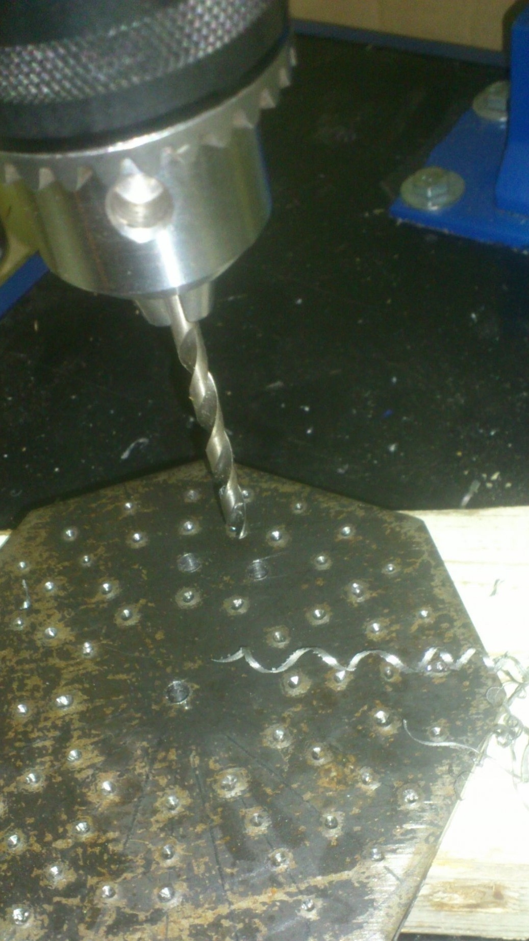
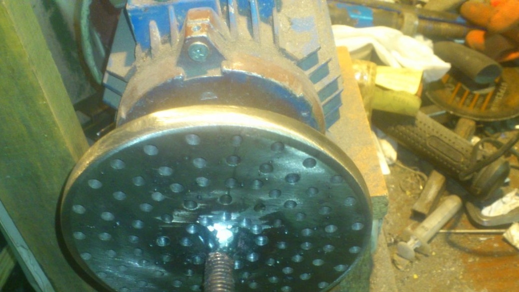
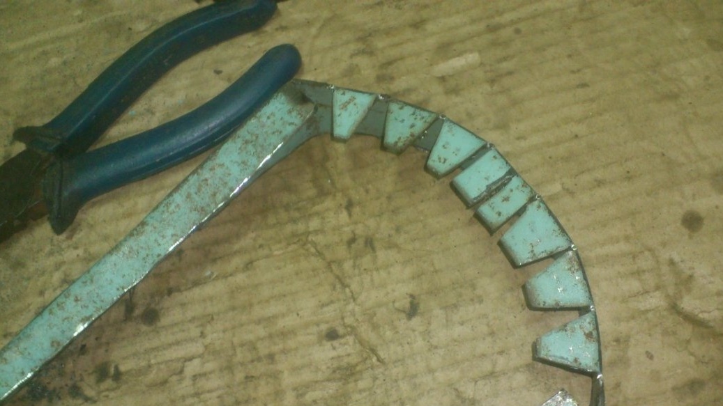
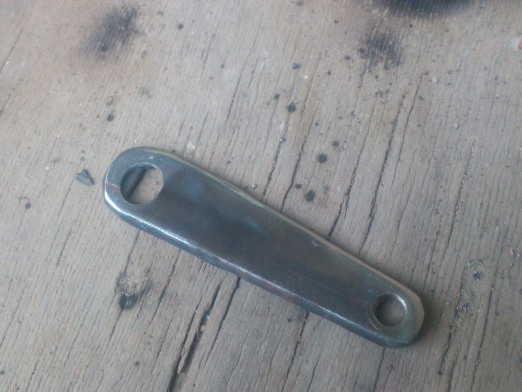
I decided to make the faceplate itself out of a piece of sheet metal - “tens”, which I found in my “necessary scrap metal”. Here is such a strange form of trim I found there:
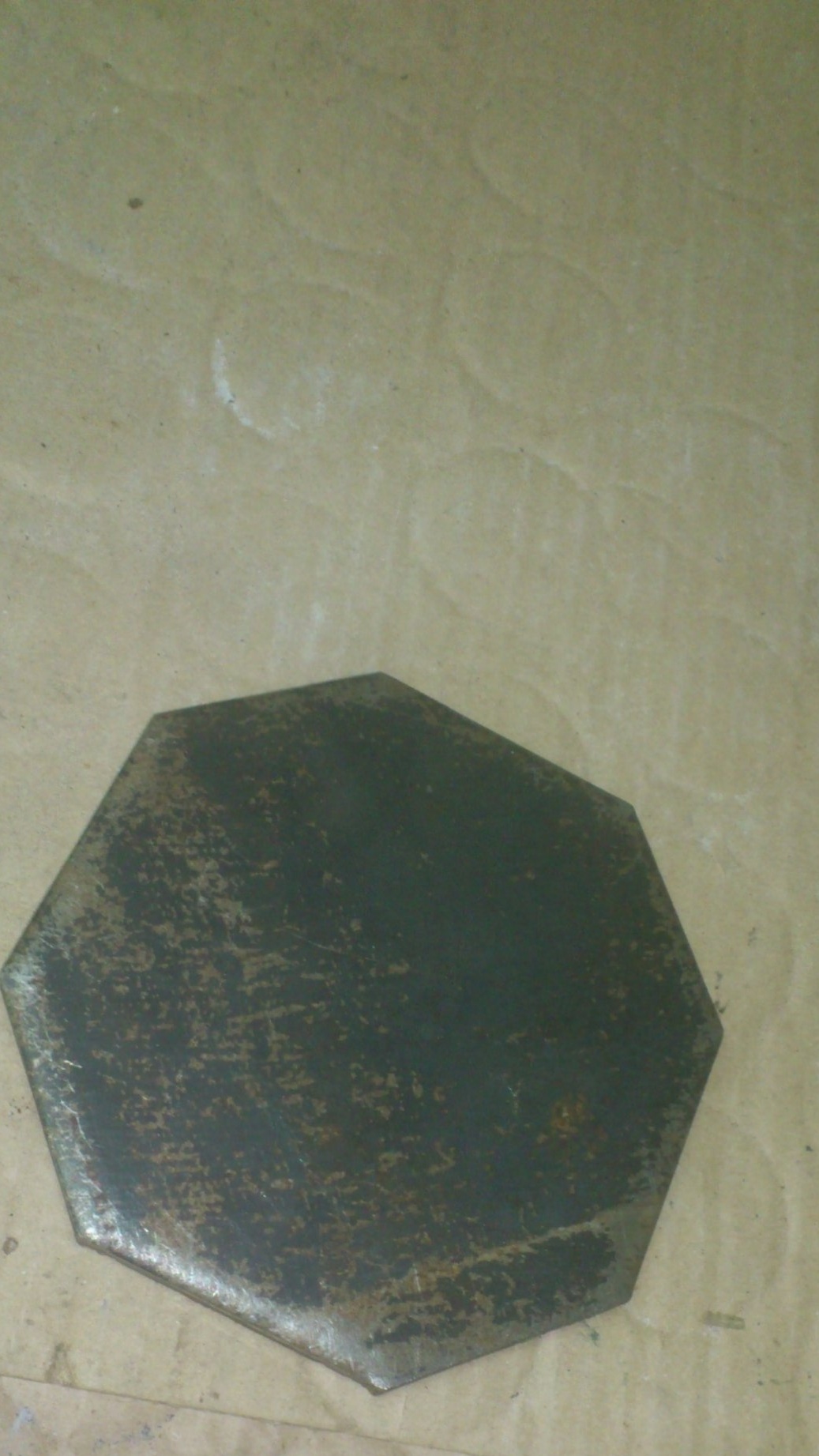
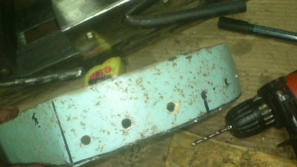
Having marked it, I drilled a lot of holes in it with a drill, 5 mm in diameter:
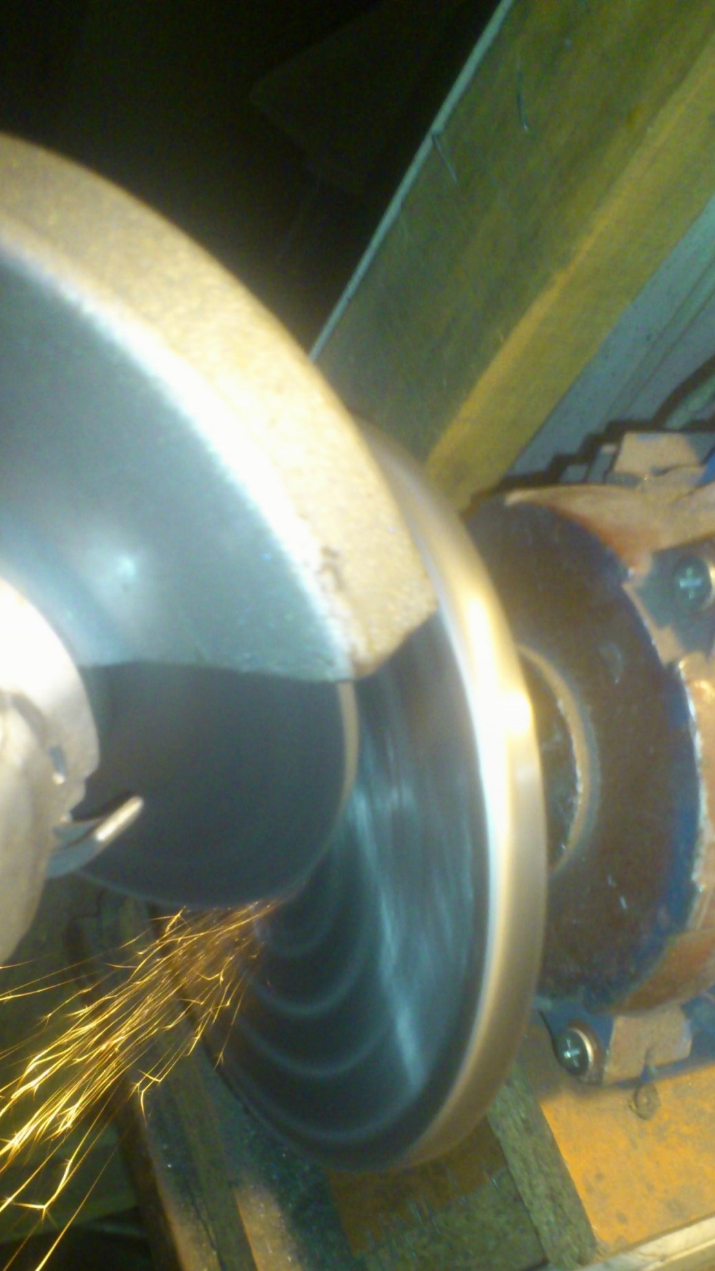
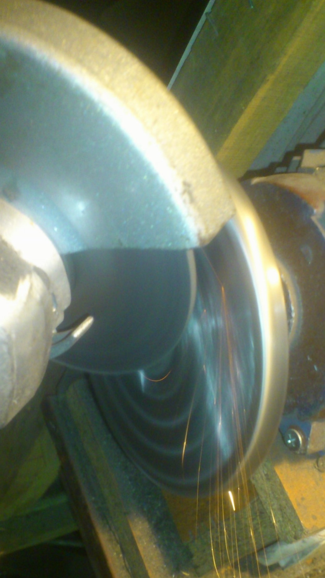
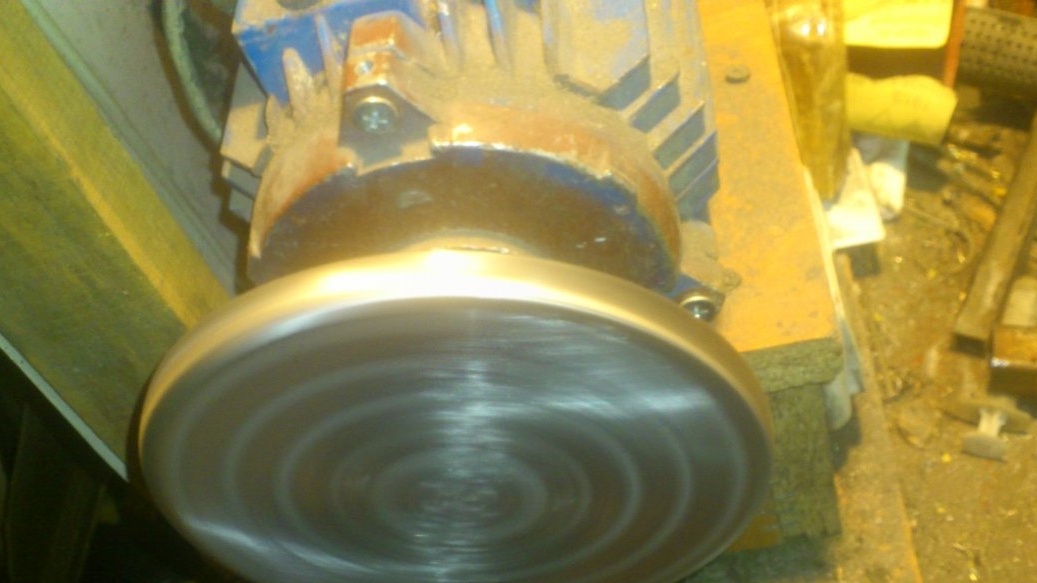
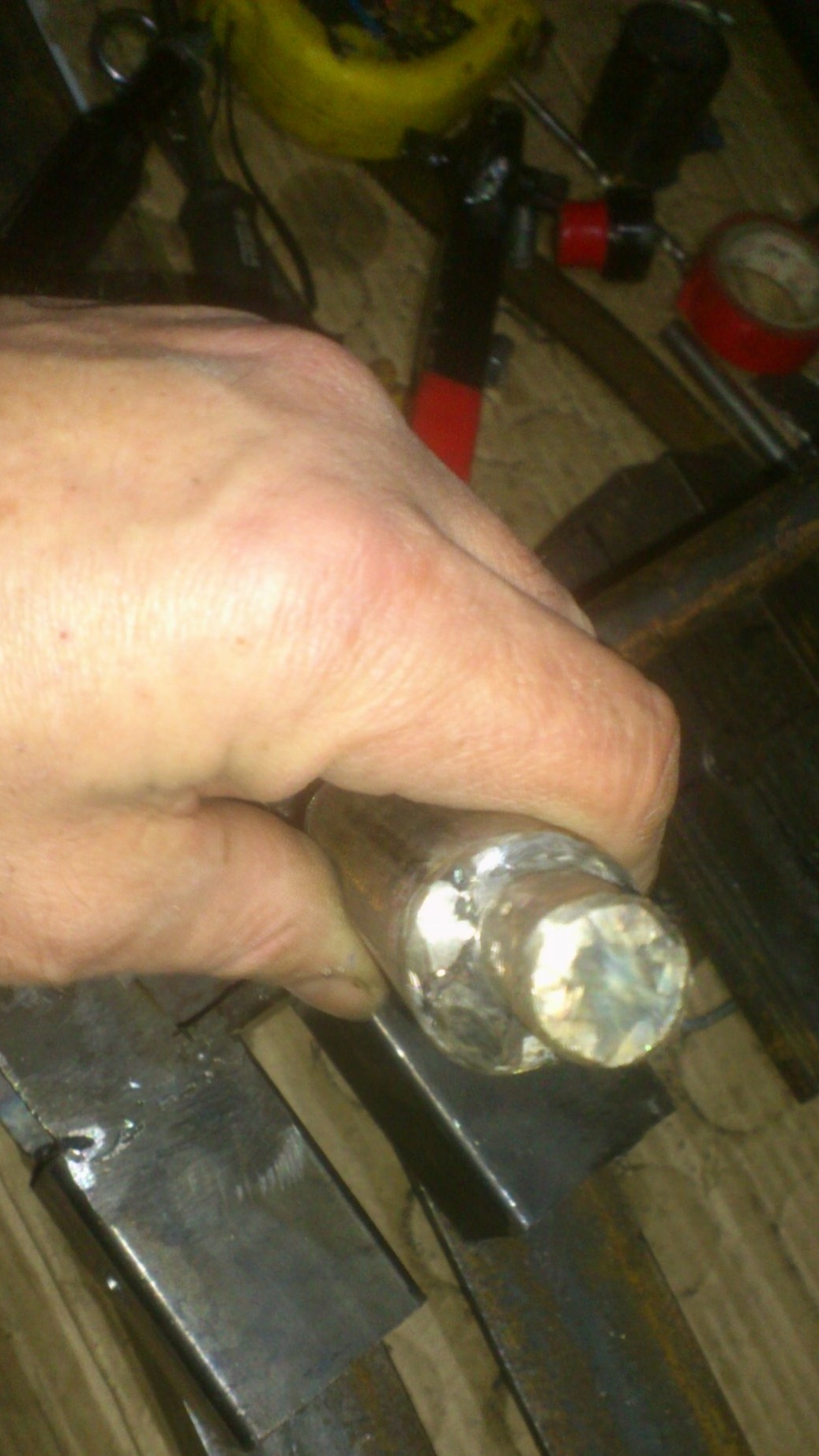
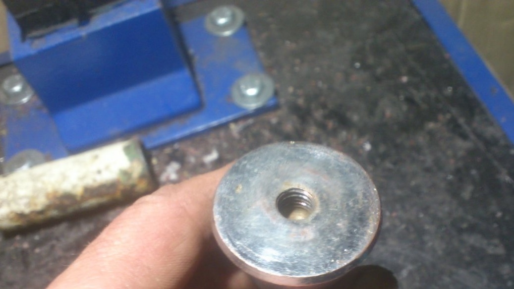
Then, having drilled an internal hole up to 12 millimeters, put it on the coupling, clamped it with a nut and .... welded the plate to the hub !!!! And then, having installed it on the motor shaft, he worked it with a grinding wheel using angle grinders:
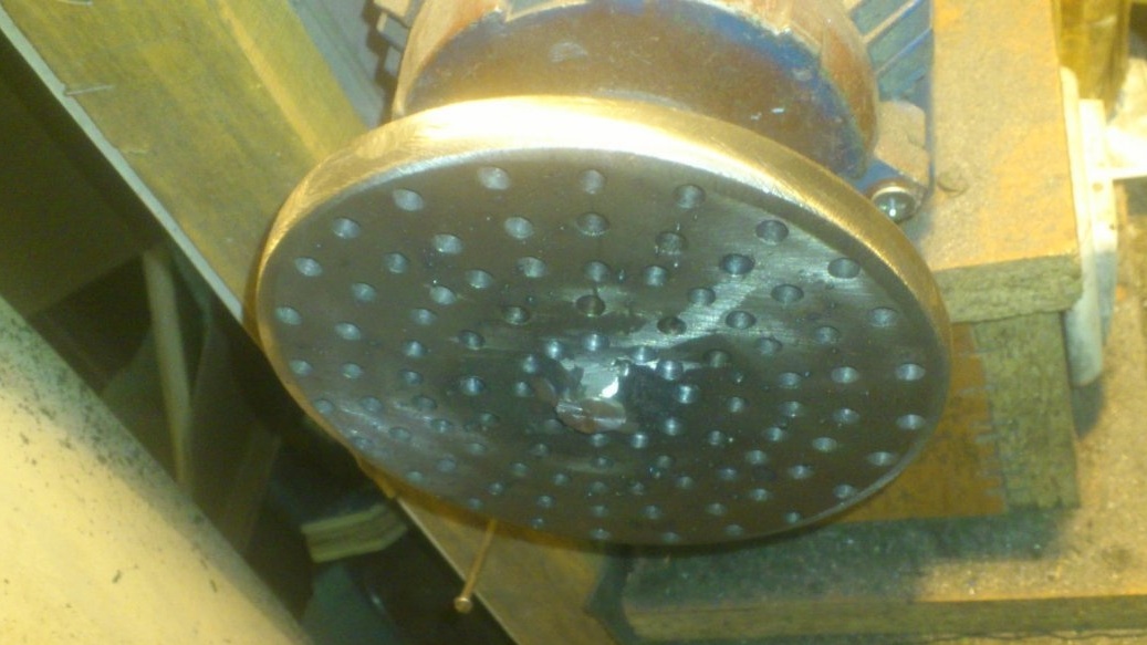
Now in the holes you need to cut the M6 thread:
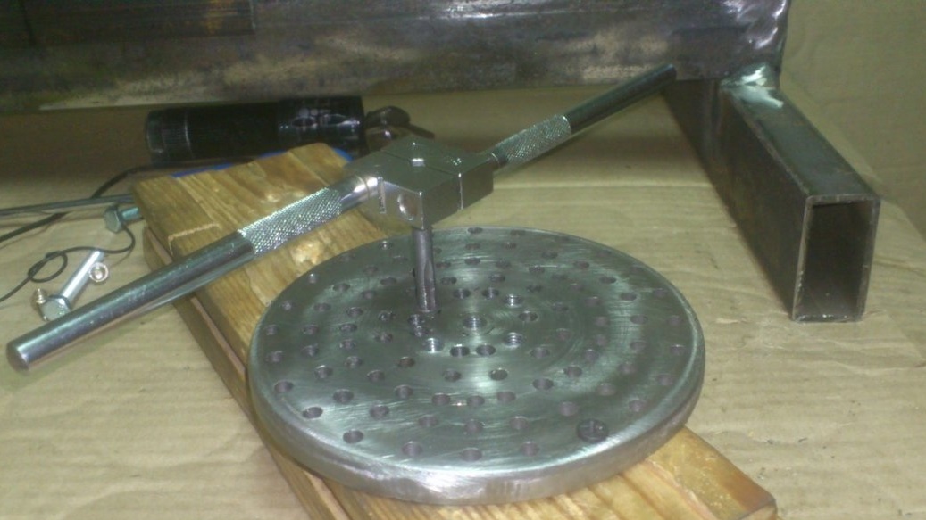
For a long time I had a pack of interchangeable spikes for sports shoes lying around (In common people - “spikes”) I already forgot when and where they came from .... I only remember that they were already in the 89th year)) )). Because, it was then that my friend, an athlete, explained to me what it was lying around with me! )))). On these spikes, the thread was exactly M6. And in the bag was the key to screw them in. That came in handy ...
If necessary, you can screw three, or five, or even more spikes, and they, digging in, will reliably hold the workpiece.
On this, I have finished work with the faceplate. Although, over time, I want to make a powerful trident that can be installed instead of spikes to fix crookedly cut workpieces. So there are also thoughts to make removable "clamps", which, fastening on the edge of the disk, will form a cartridge, clamping the workpiece mounted on the spikes from four (or six) sides. This is in order to remove after that the tailstock and process the end face of the workpiece ...
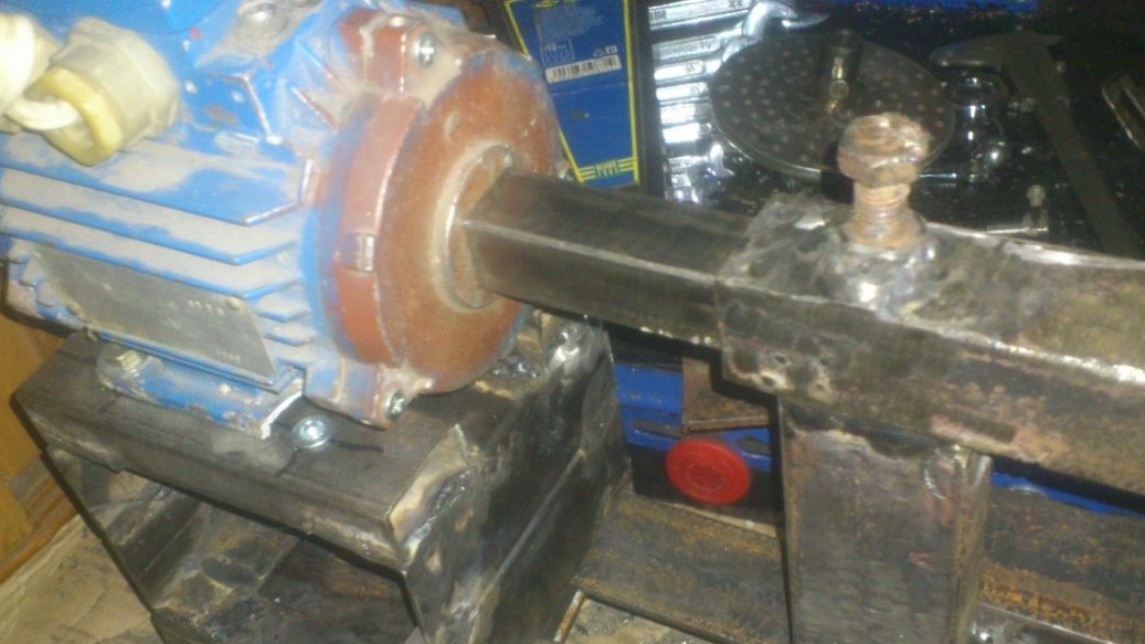
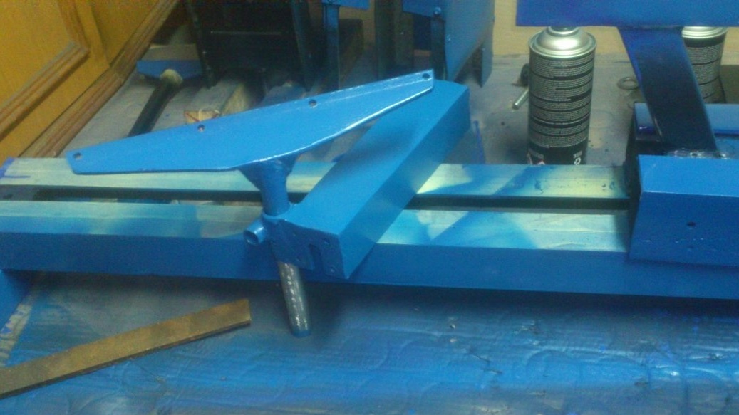
In the meantime, continue with the front headstock:
I reinforced the stand with angles of 50 by 50 and a strip of 50 by 5:
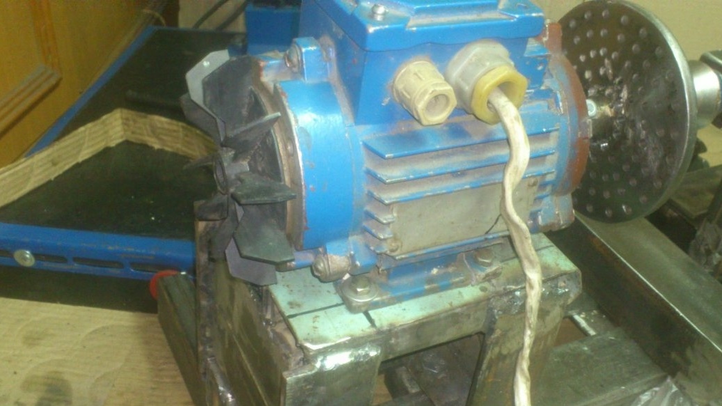
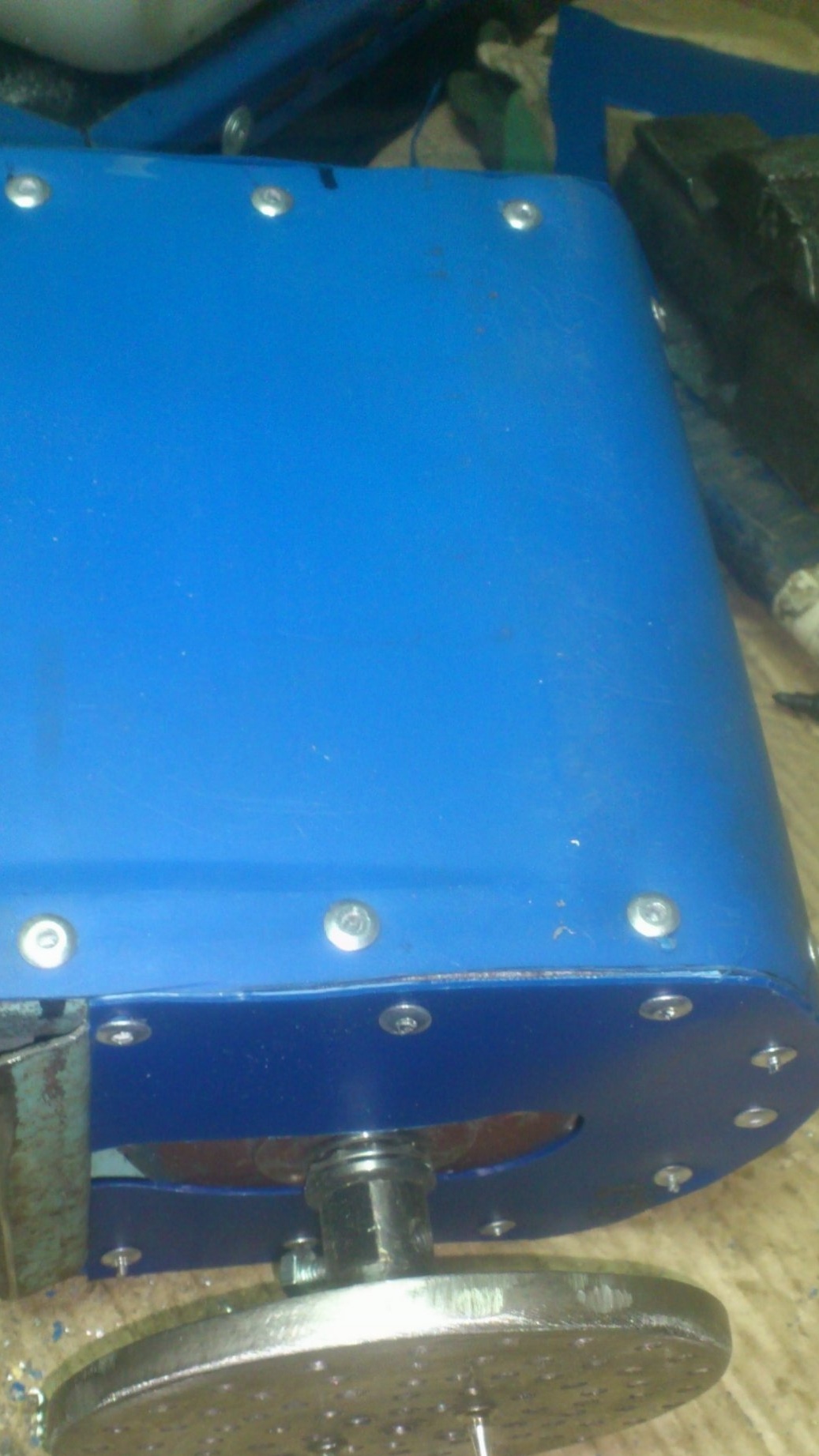
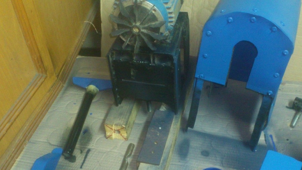
Then he took up the corps. I decided to hide the motor in the case for a simple reason. Since long ago, two polishing wheels stood on it, the impeller with the cover was lost. I picked up the impeller according to the diameter of the shaft, but I did not find the cover. Yes, and the new impeller was more than regular. Without a cover, air flow will not be directed along the edges of the housing. And I decided to make a body for the entire motor. Inside it, the impeller will drive the flow forward. And nowhere else)))).
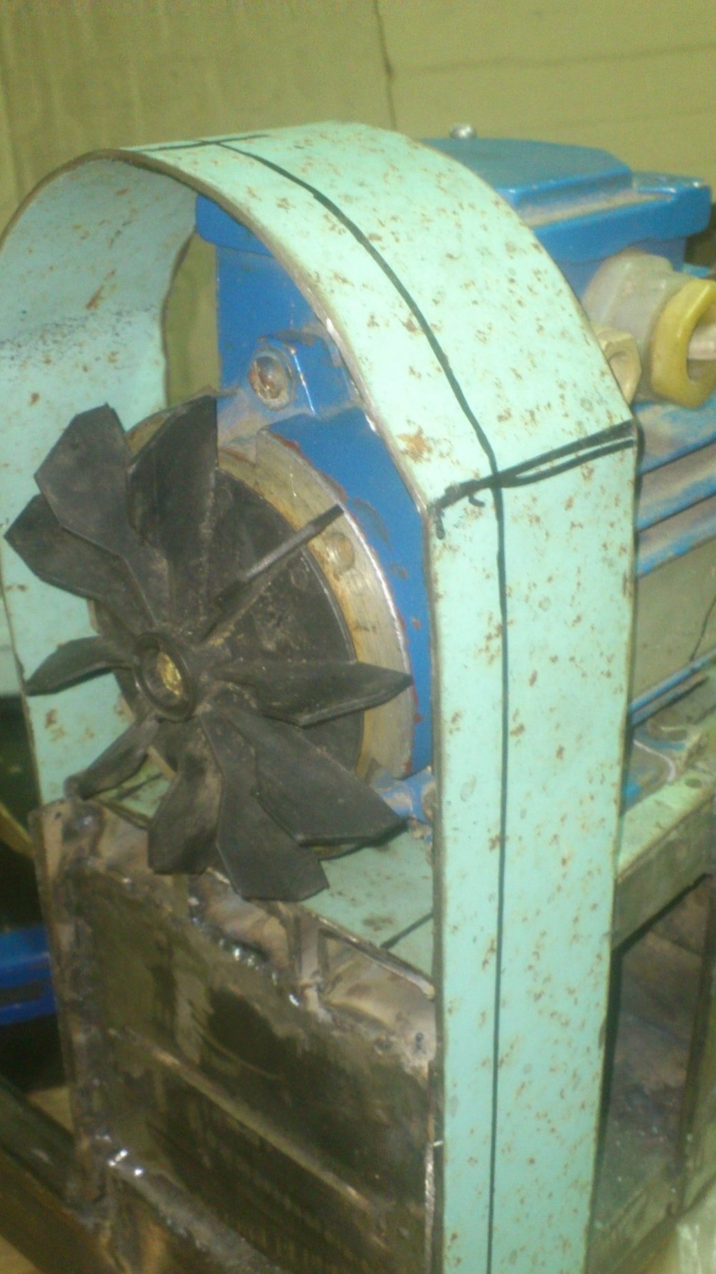
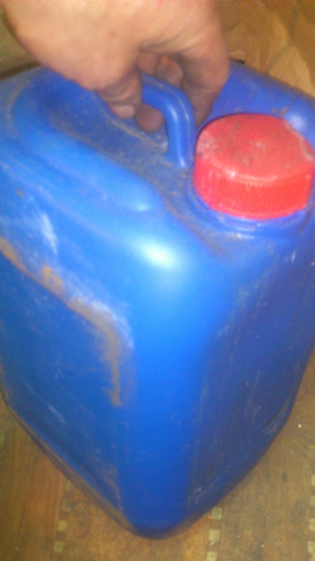
The frame is ready.I decided to make the walls plastic (so as not to resonate). To do this, cut the canister and used its walls to sheathe the frame. Secured with rivets:
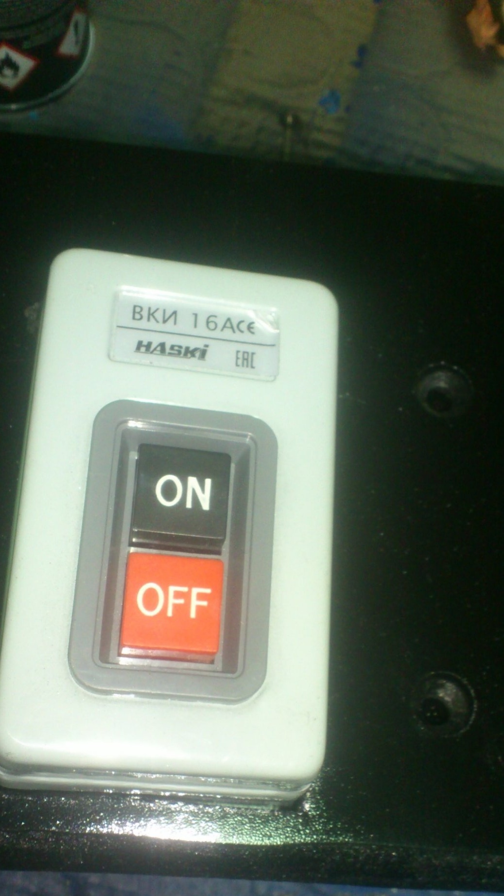
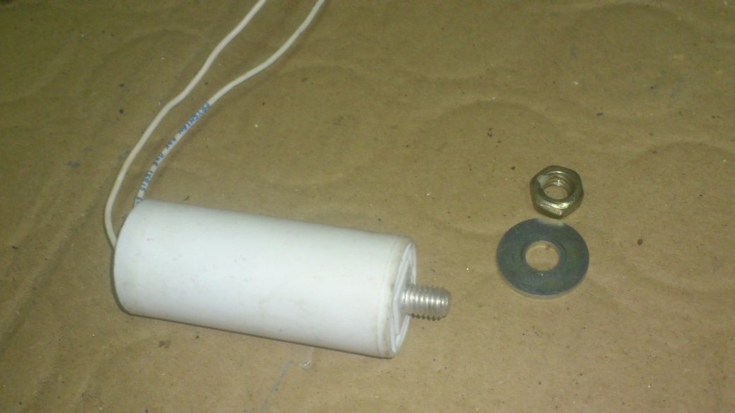
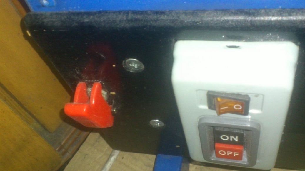
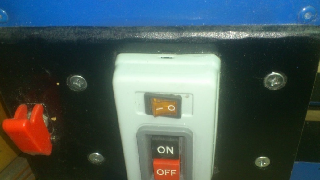
To turn on the machine, I did not use a contactor (magnetic starter). Since the motor is single-phase and the power is not large, I decided to use this ready-made power-on post:
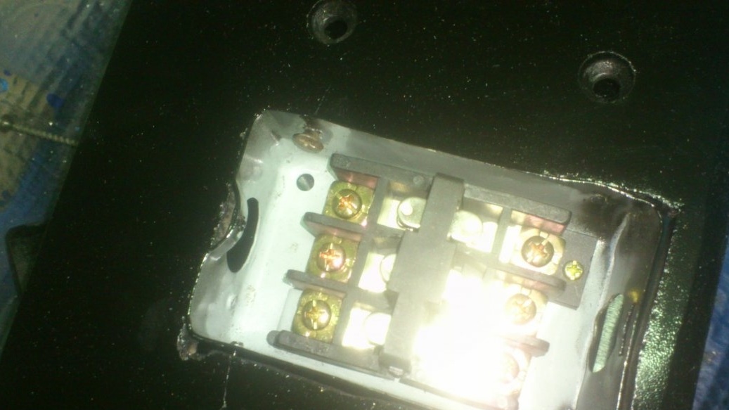
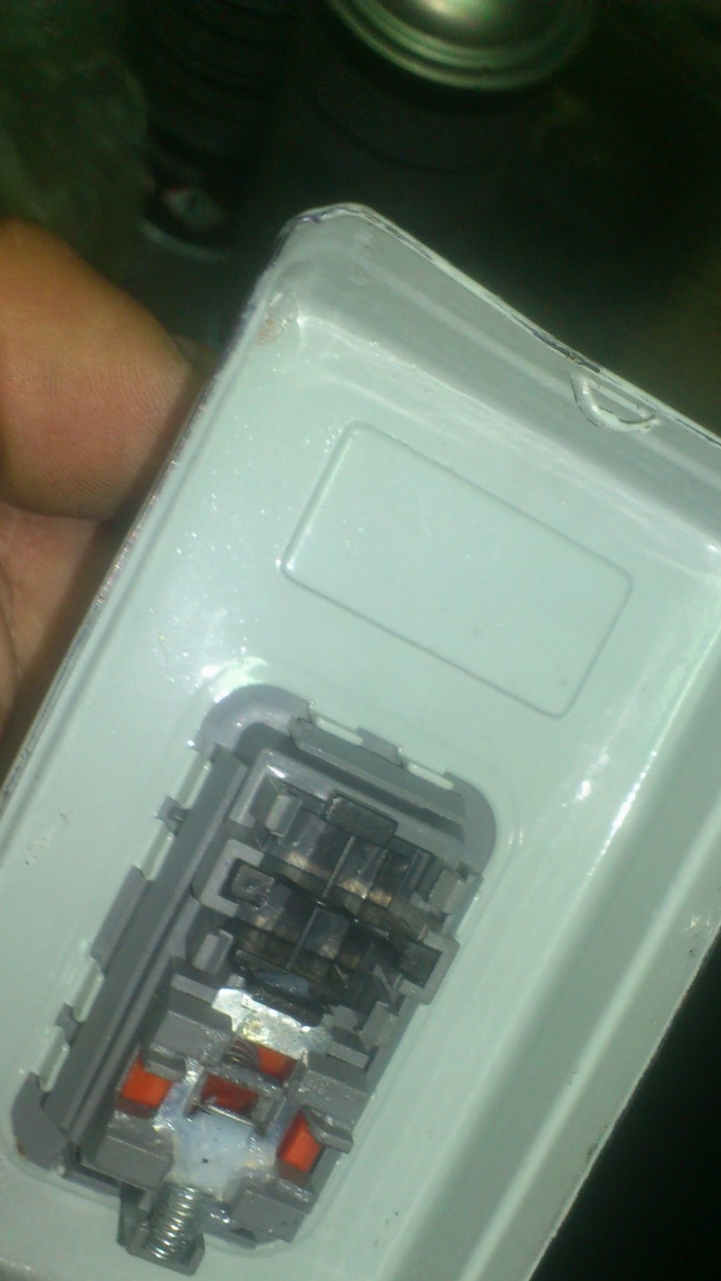
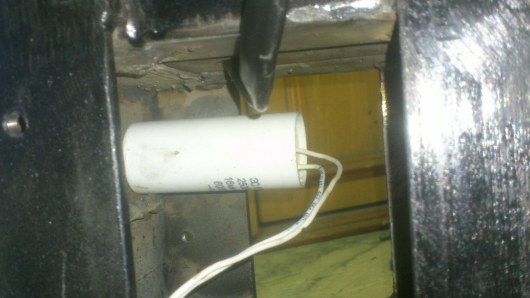
After measuring the resistance of the windings, I found that the motor is completely reversible - the resistance of both windings is the same. There is no difference which one is working and which one will play the role of a launcher, being fed through a bias capacitor. (By the way, I fixed the capacitor itself inside the headstock):
I connected the engine according to such a scheme, providing this with a reverse:
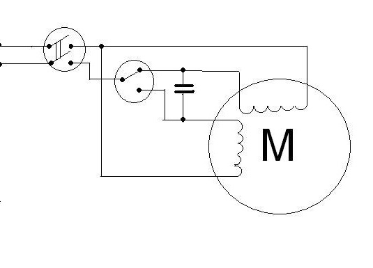
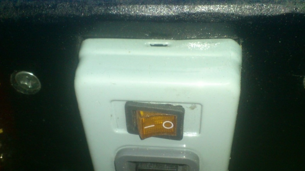
As a reversing switch, I used a conventional toggle switch, protecting it with such a cover:
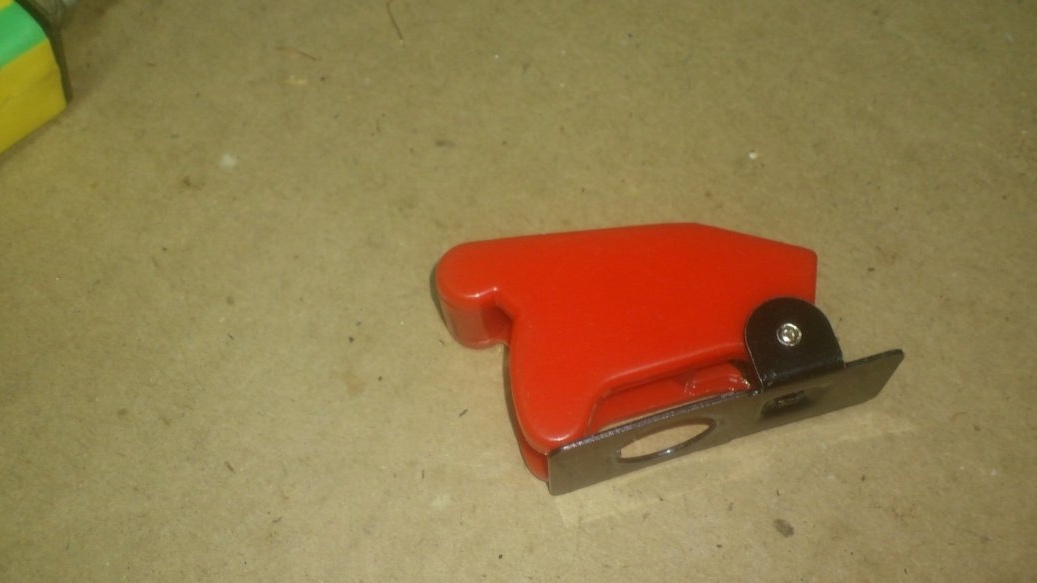
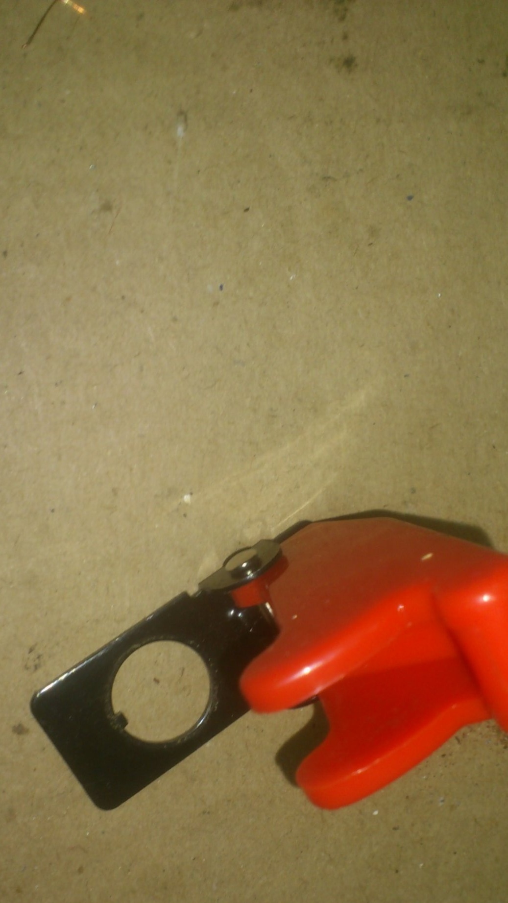
Protection against accidental inclusion is needed so as not to cause trouble by switching the windings during operation, or until the rotor stops completely (after all, while the rotor rotates, the engine, in essence, is a fairly powerful generator!).
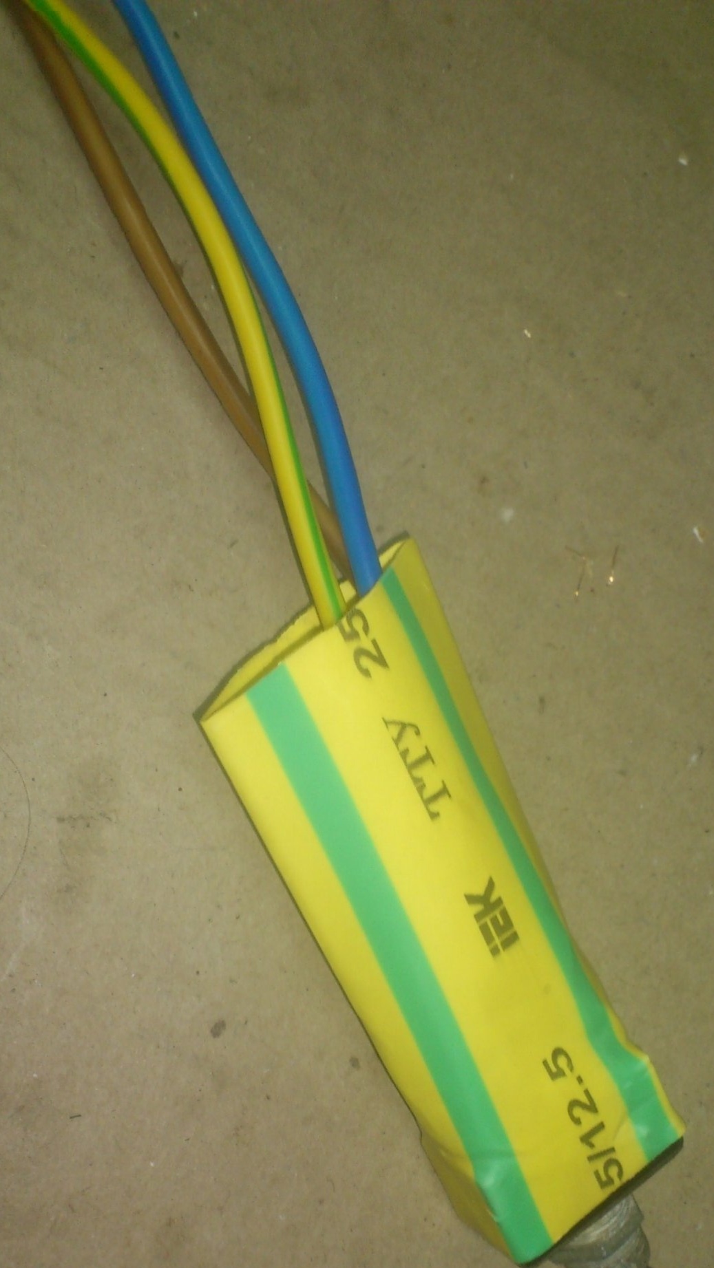
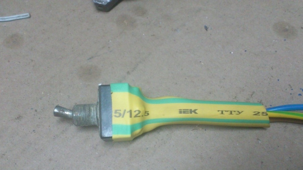
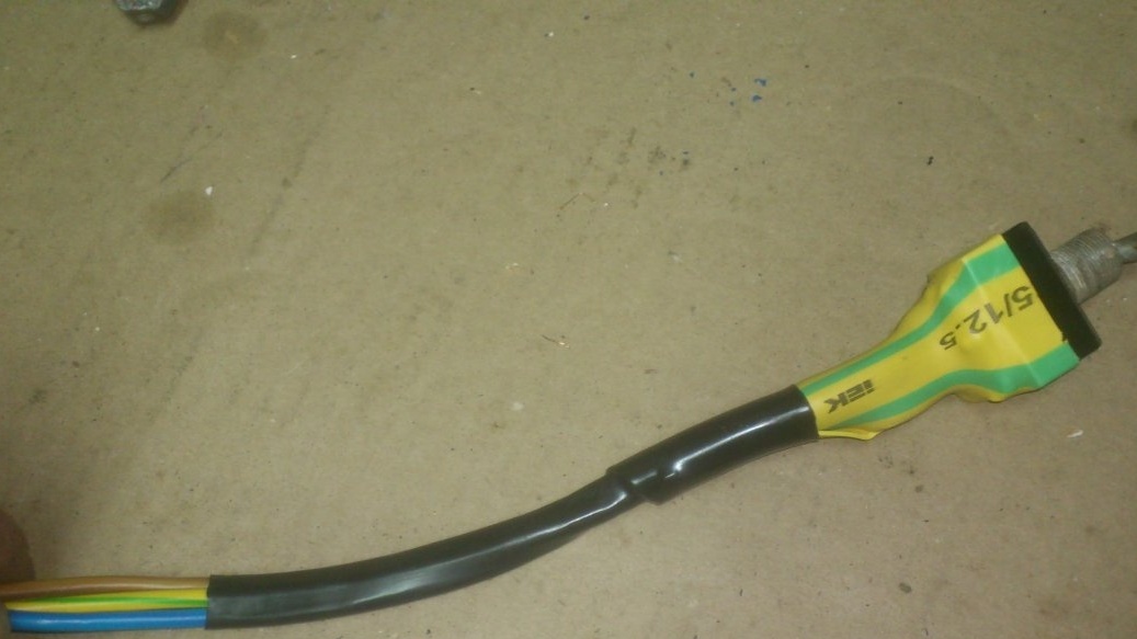
He protected the electrical connections on the toggle switch with a heat shrink tube:
Now we need to somehow install all this in the engine housing. I drilled holes in the uprights of the headstock and cut the M6 thread into them:
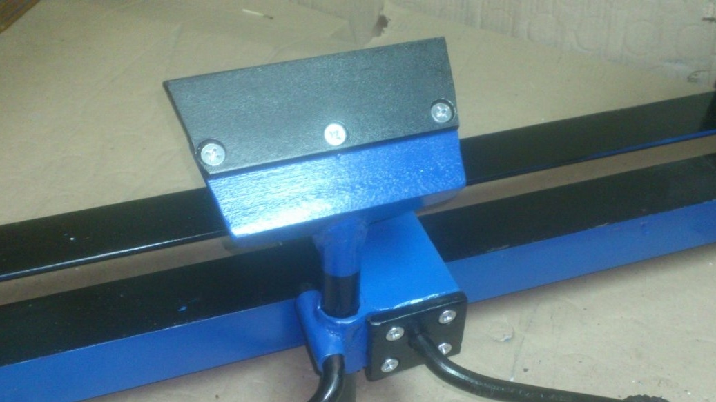
Using them, I fastened the housing to the headstock with screws. With the same screws, I decided to fix the panel with the switches. I made the panel itself from the trim of the laminate, which had been lying in my “necessary rubbish” for a long time:
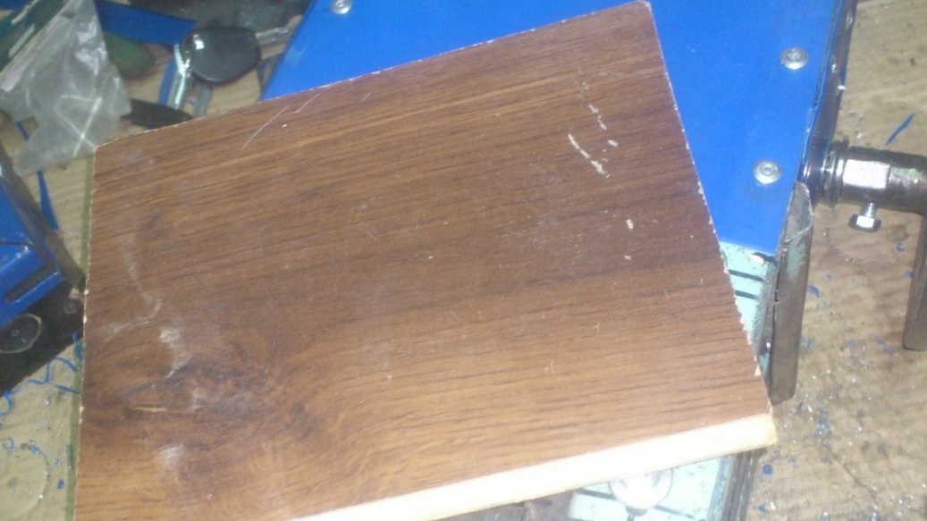
I screwed the screws back into place, laid the scrap of laminate in the way it should be fixed, and tapped the screws above the screws. The pattern of the hats was imprinted on the laminate, and I drilled the holes exactly where they should be:
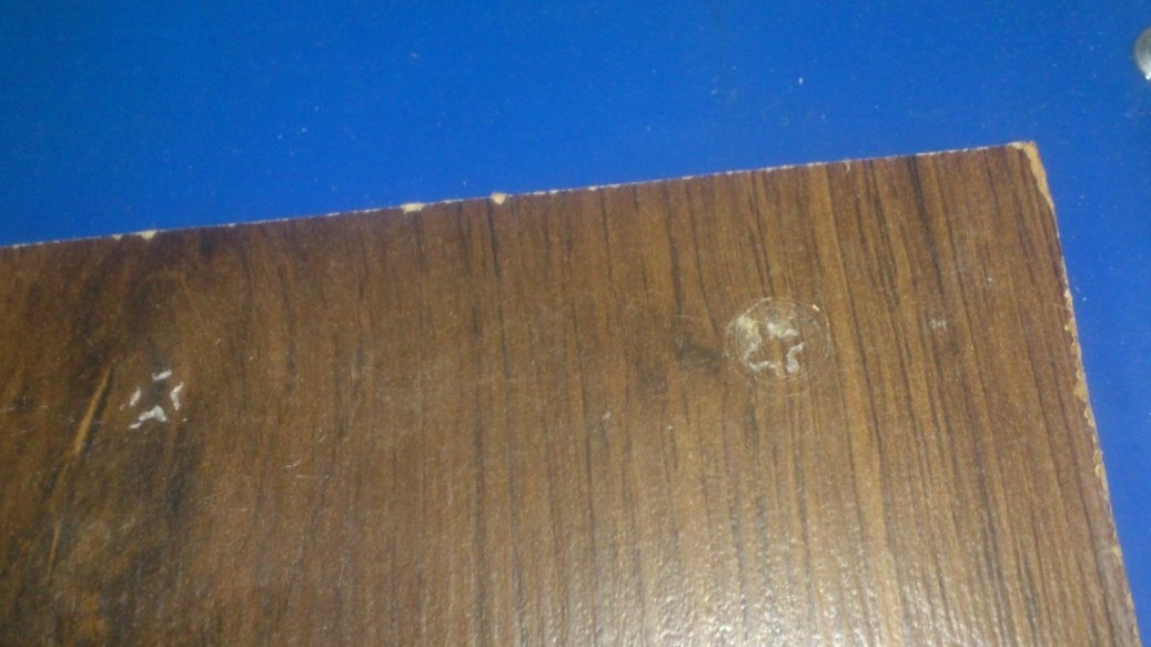
This is the kind of control panel I got for the machine. I inserted a small switch for the backlight into the main switch housing. (there was a place).
Now I will describe how I made the tailstock.
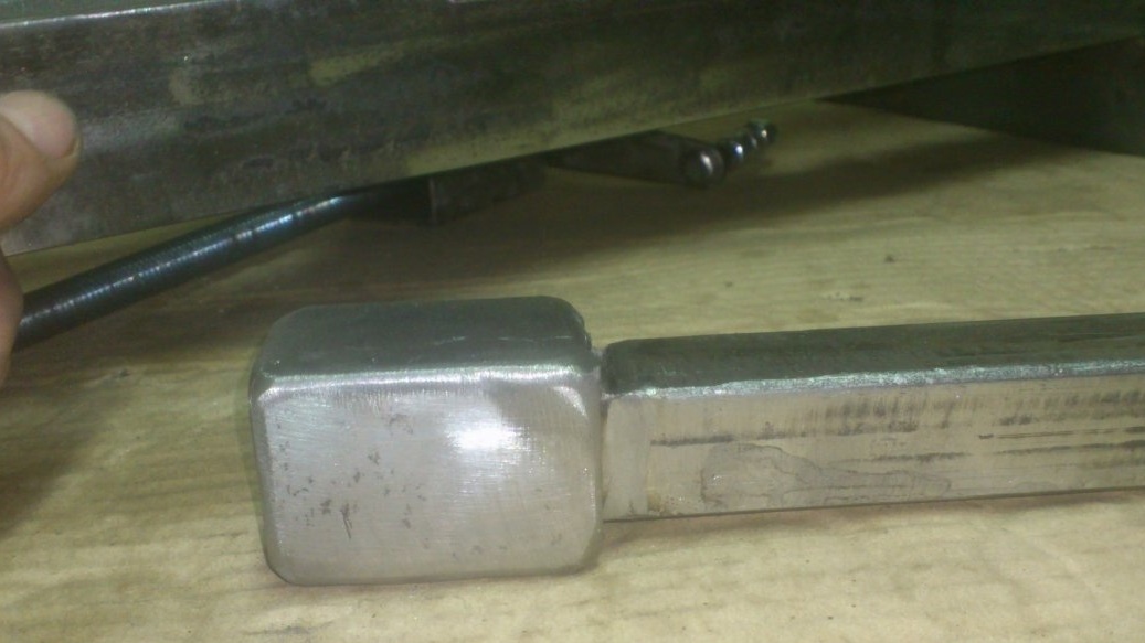
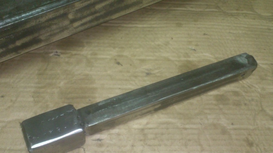
I welded the bed of the tailstock from the scraps of profile pipes 50 to 50 mm:
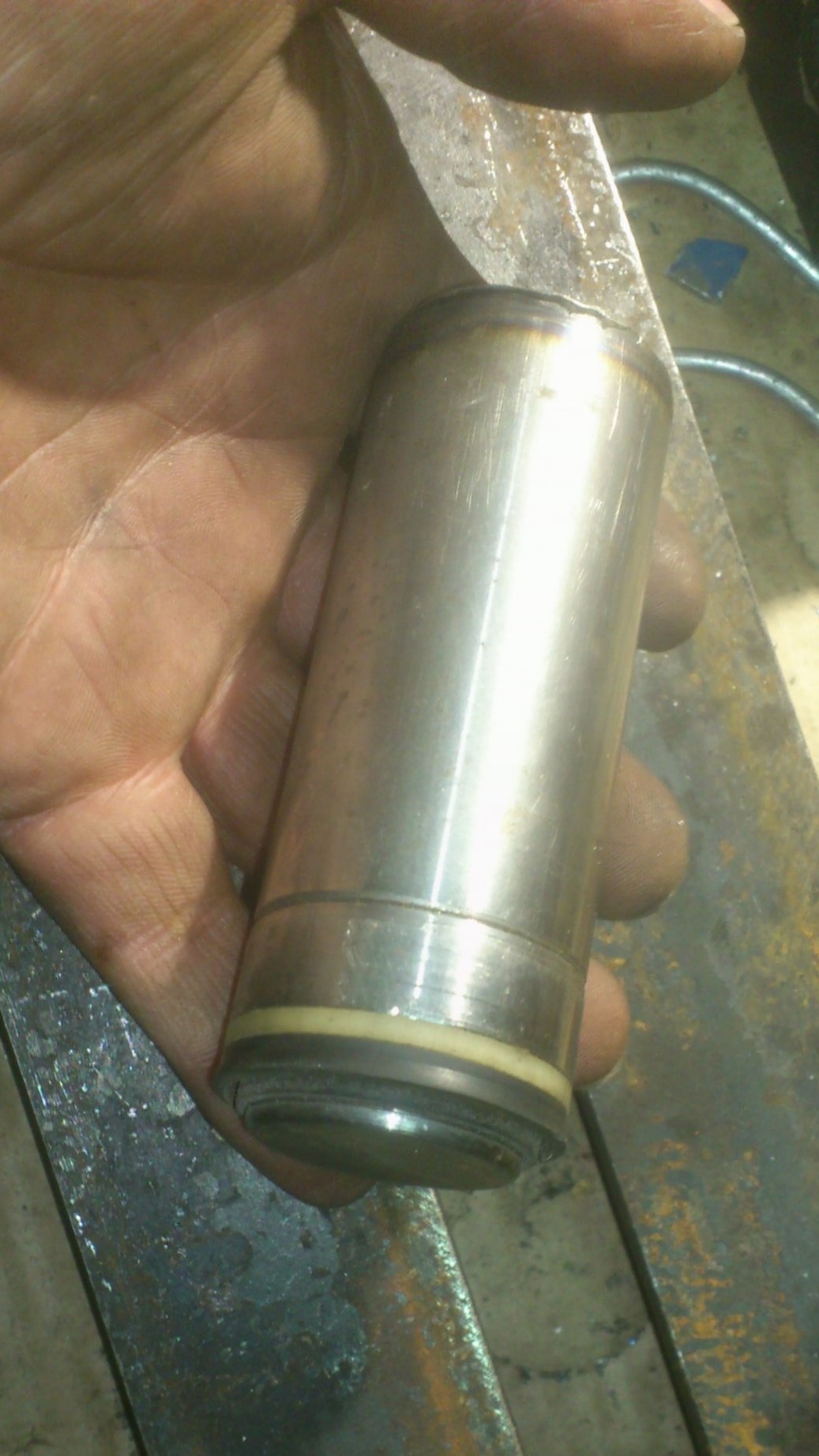
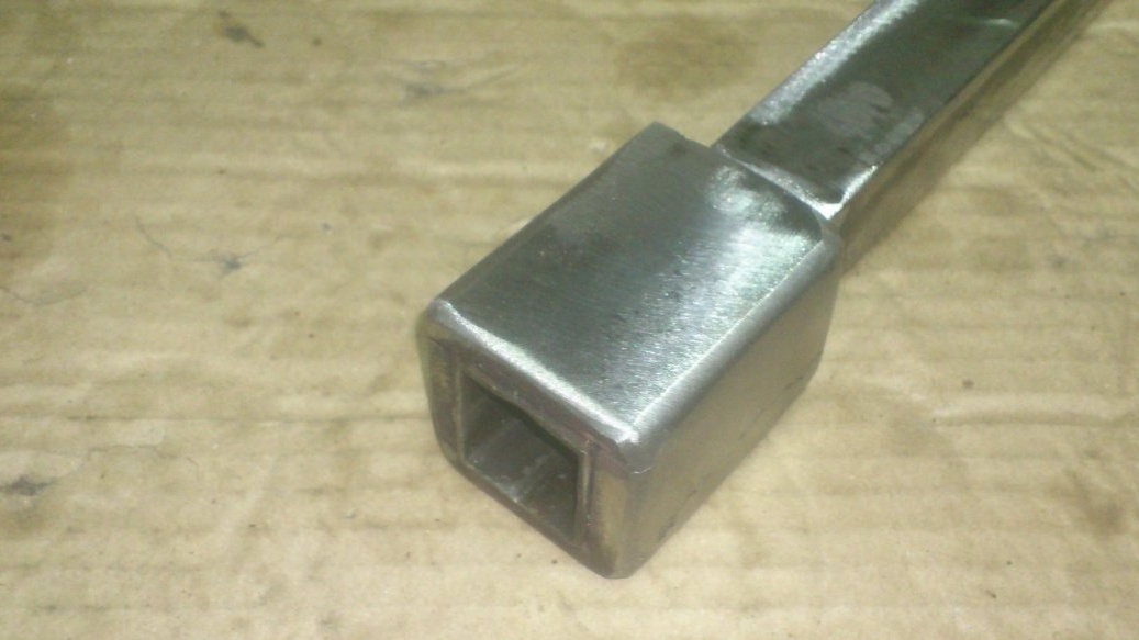
Inside the transverse section of the pipe, I placed the shaft of the eccentric mechanism. Made it the same method as the eccentric shaft a handyman. That is, he put a piece of water pipe on the round, stuffed the wires between them on one side, scalded and cleaned it. Only this time the shaft was made more powerful - the DU-20 pipe, a round log with a diameter of 16 mm:
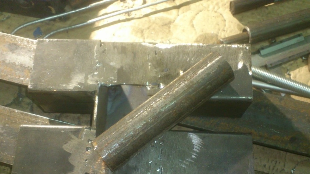
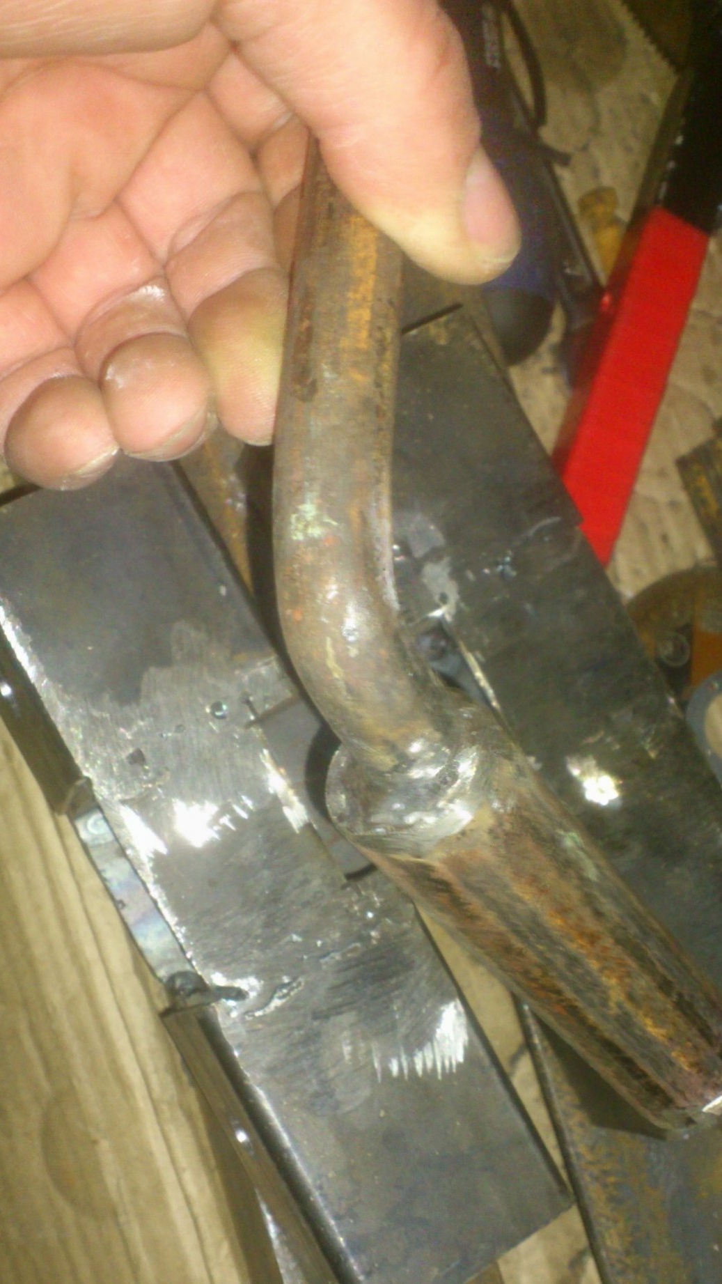
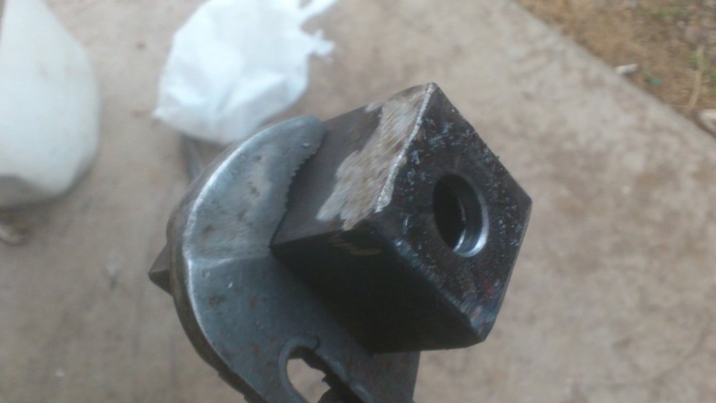
For a leash, I used an M12 bolt for 100 and a piece of the thick-walled pipe that remained after I, when making a pipe bender, sawed the hydraulic cylinder of an old jack:
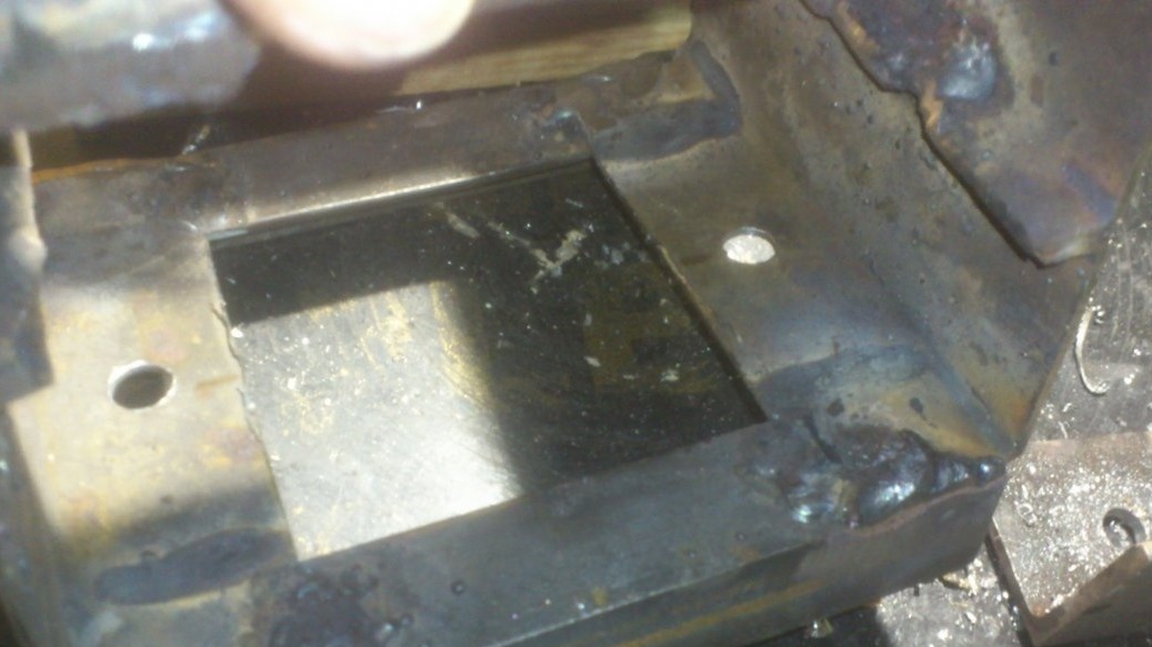
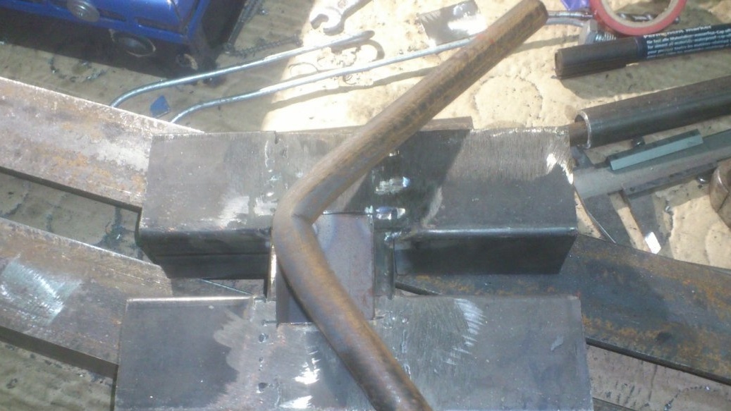
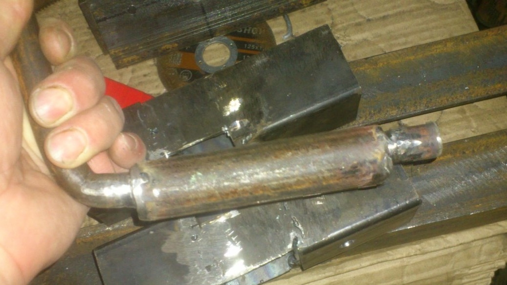
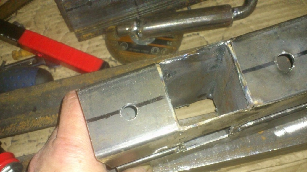
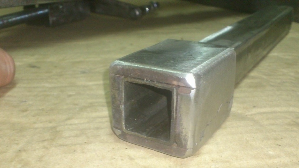
To withdraw the leash, I cut a square hole at the bottom:
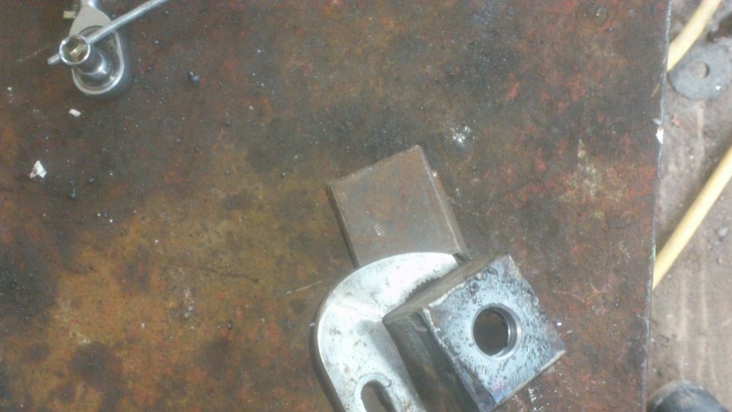
And I decided to fix the axis of the shaft by screwing it to the side planes on both sides at an angle of 50 to 50 with a hole in it. (I didn’t take a picture, sorry. But later you will understand everything in the photographs of a ready-made mechanism)
To fix these "side covers, I drilled two holes for threaded rivets:
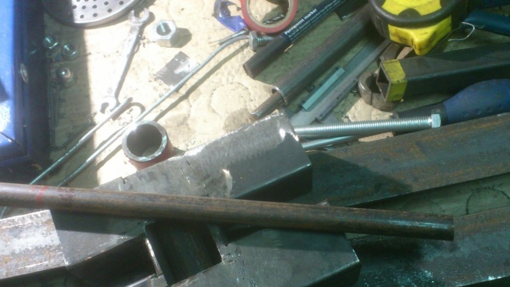
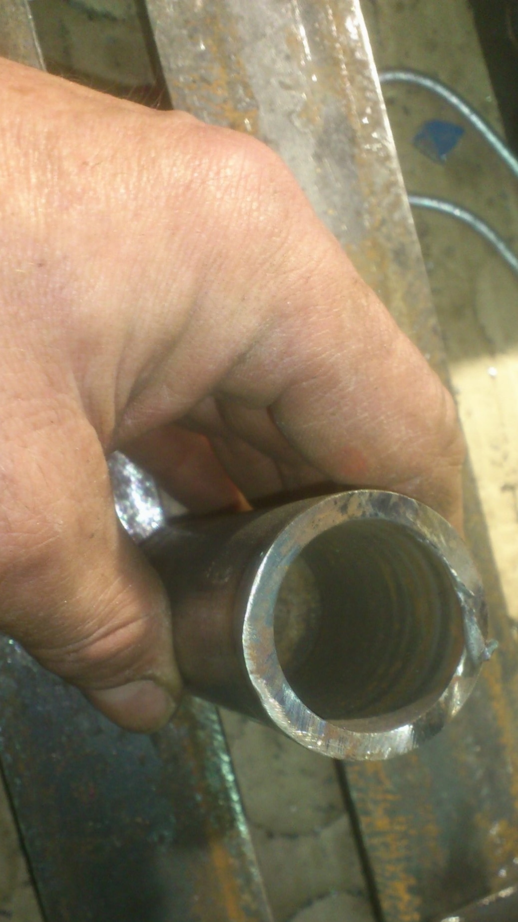
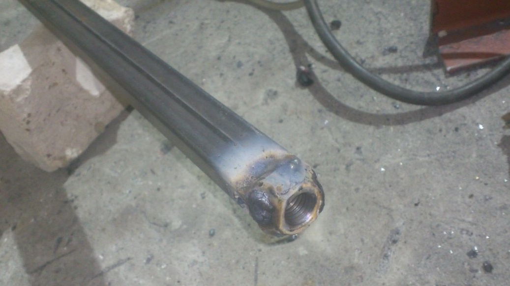
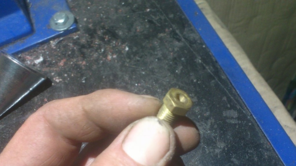
Now about the pinol. I decided to make it from a profile pipe 25 by 25 mm. From the back, I welded an M14 union nut to it.
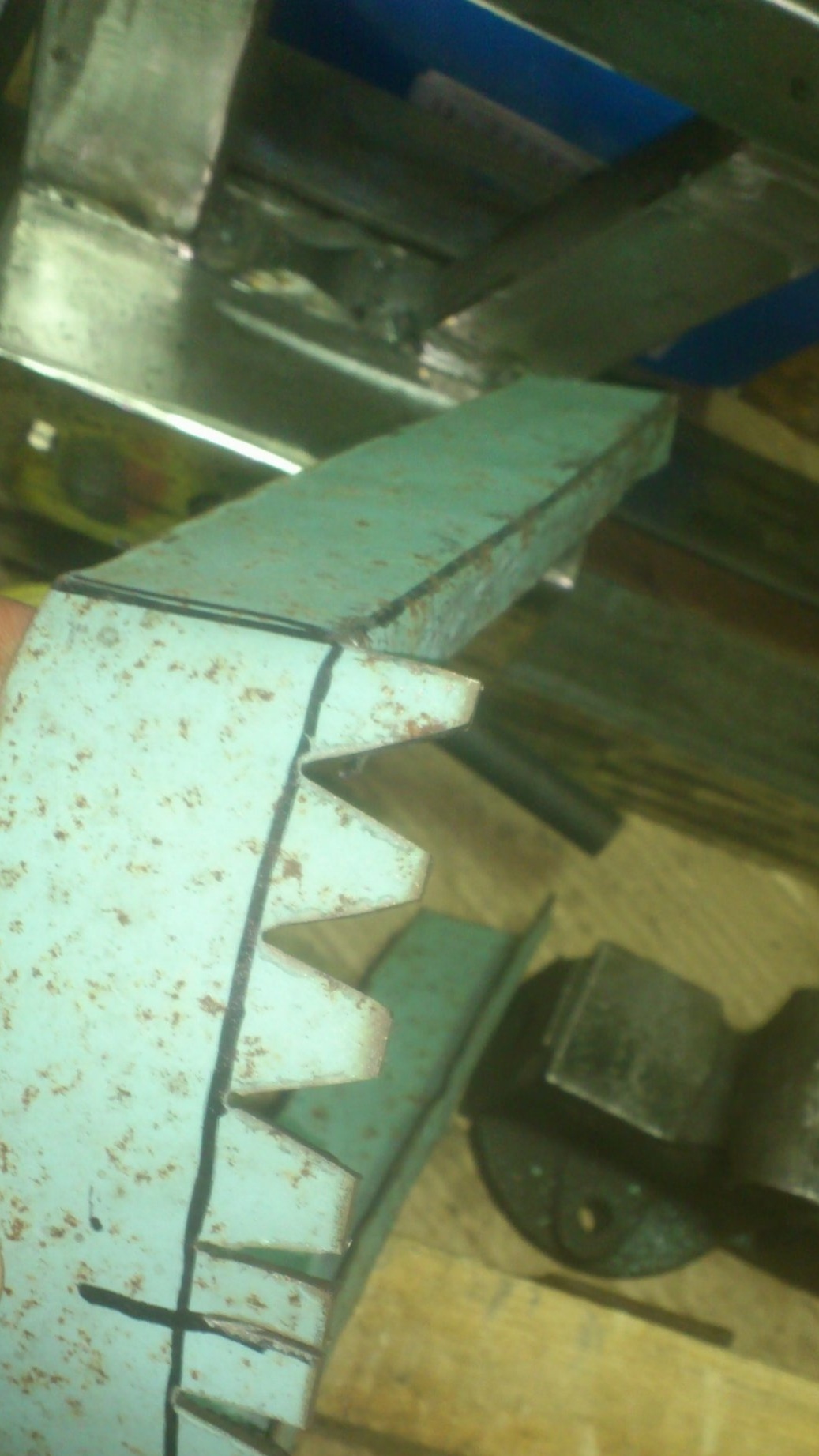
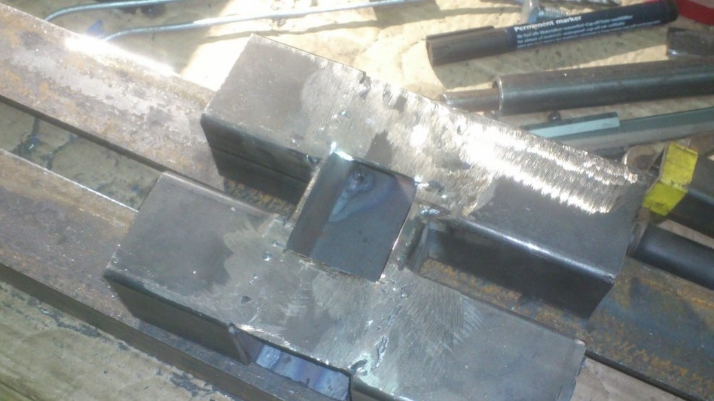
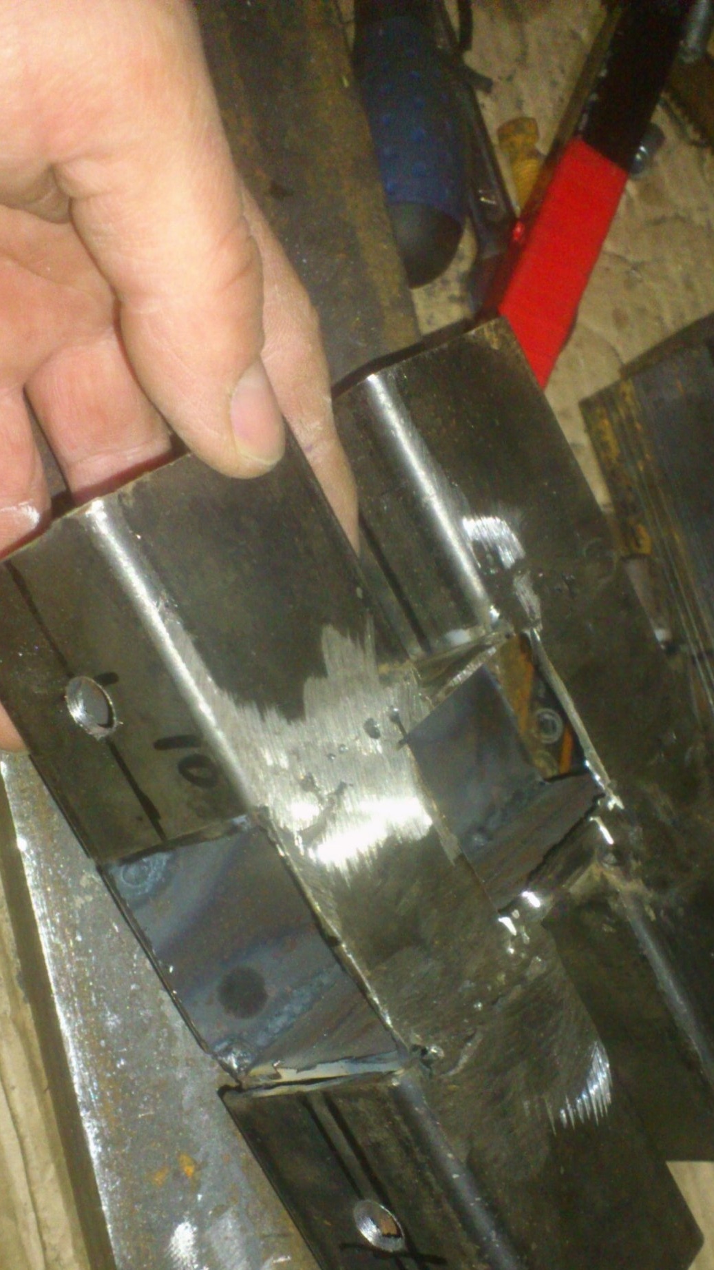
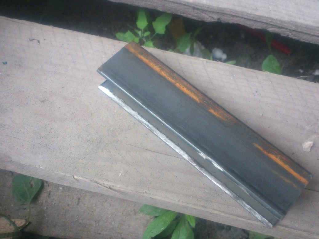
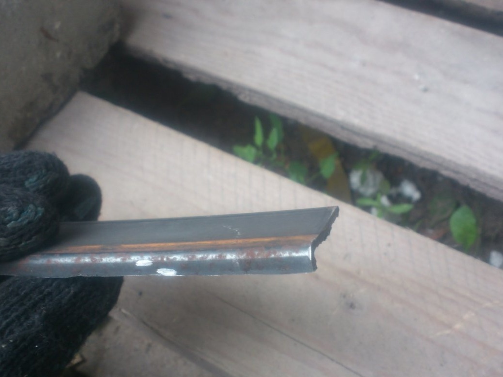
For the manufacture of the pinoli case, I needed two pieces of the corner. First I removed the rounding in from the inner corners:
This is necessary so that the profile pipe can be tightly enclosed in the corner:
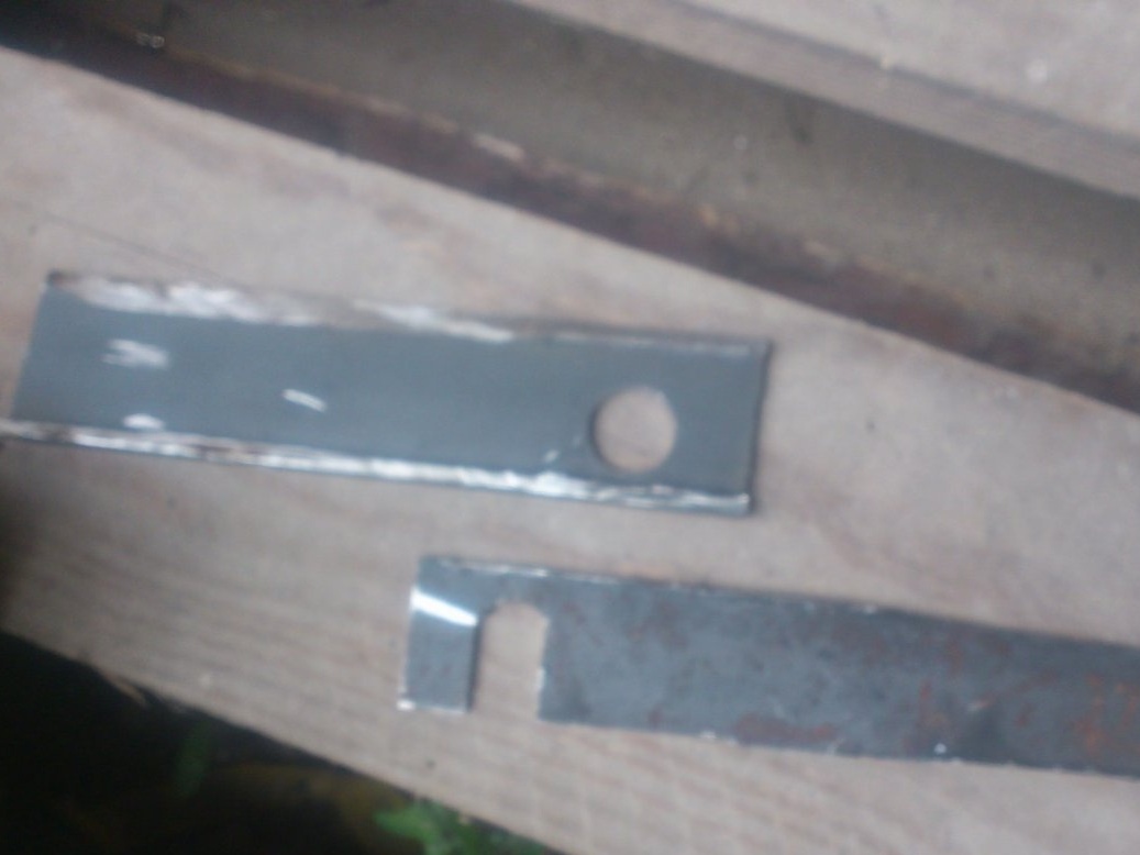
After that, I marked the dimensions with a marker and cut off the excess:
Now you can fold the corners "around the pintles", tighten with clamps and weld:
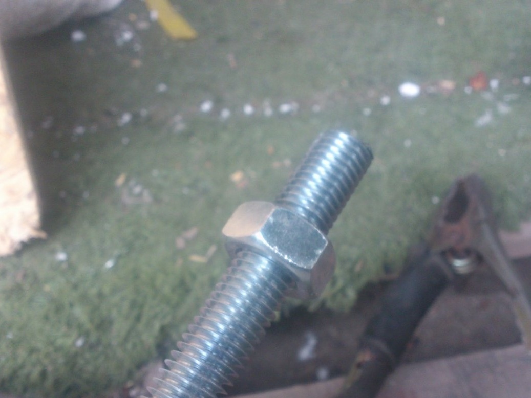
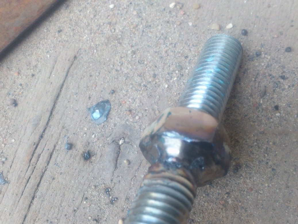
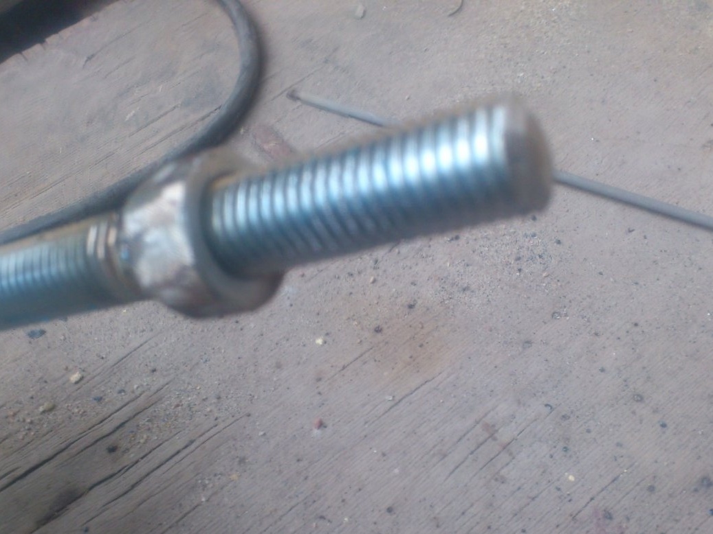
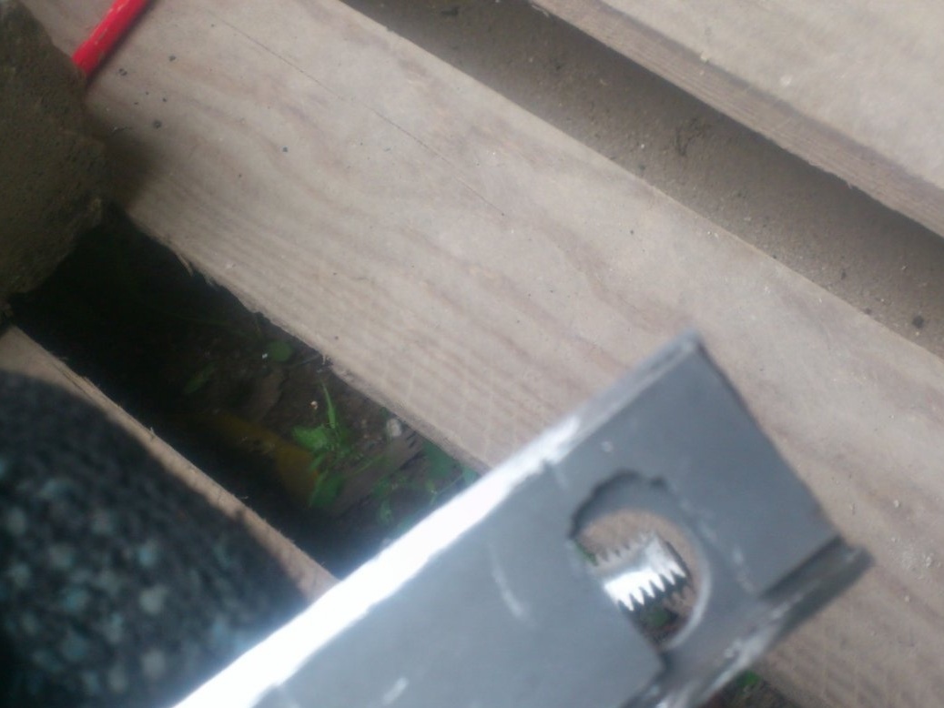
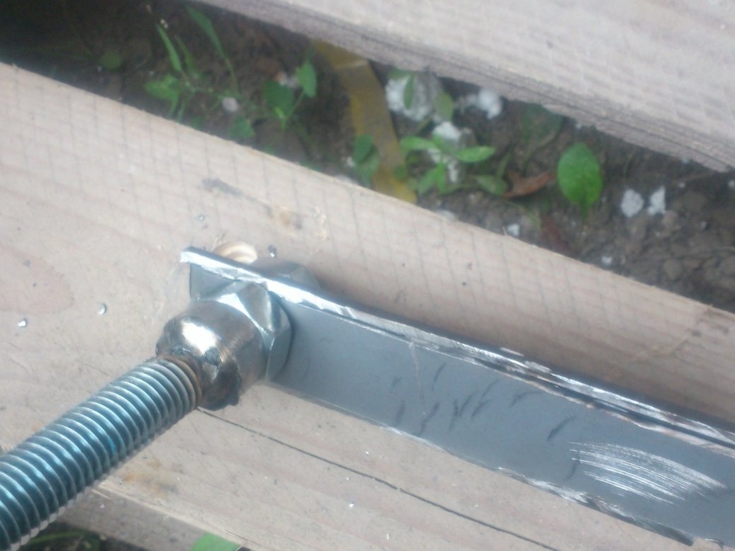
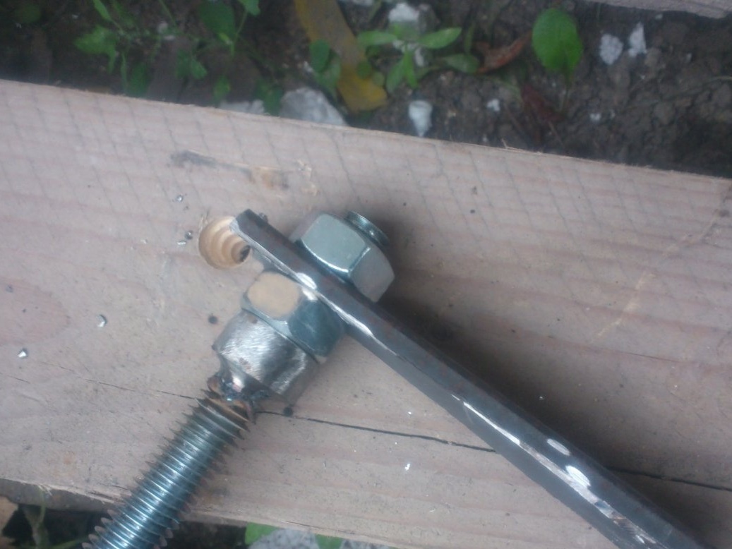
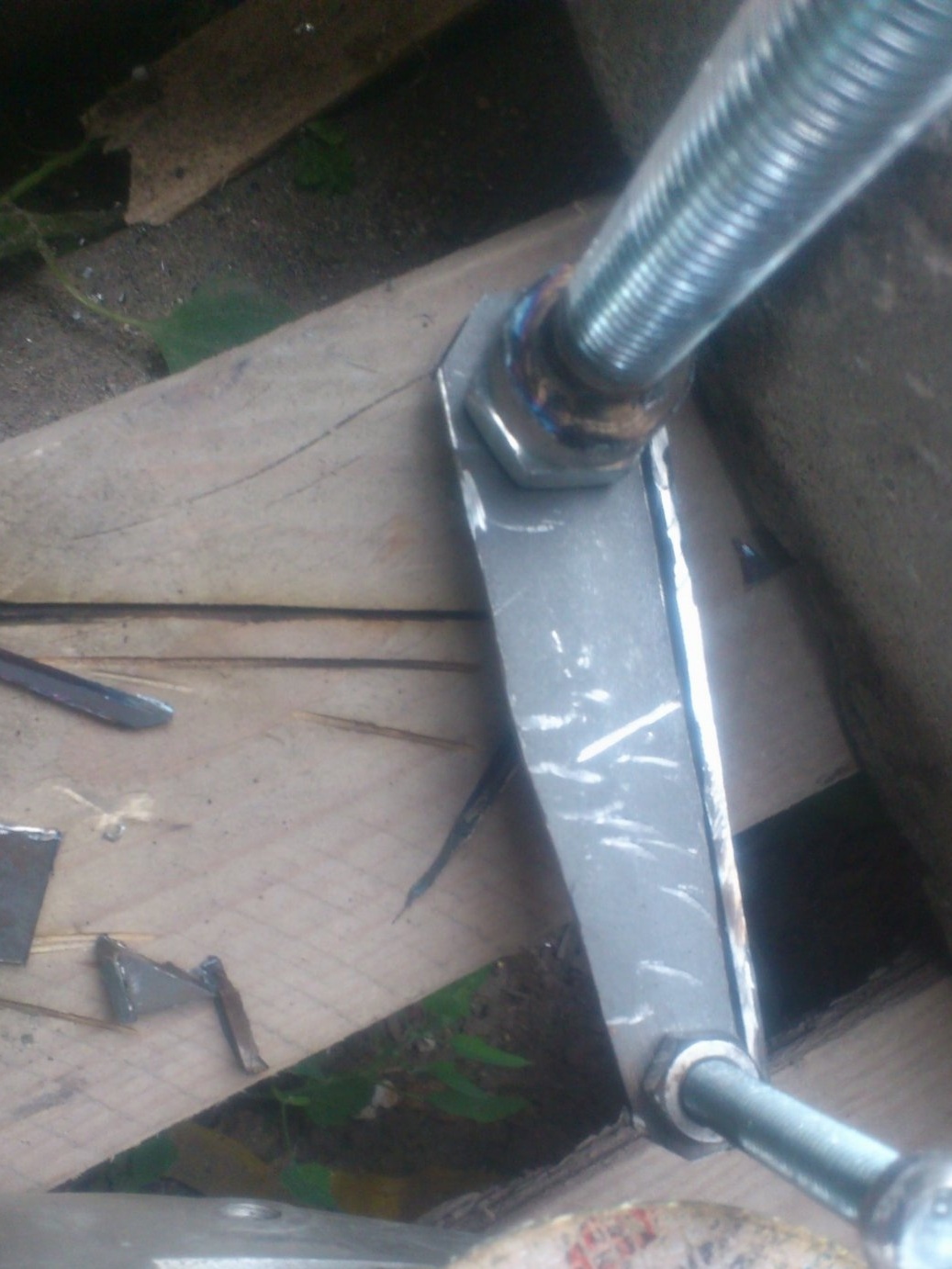
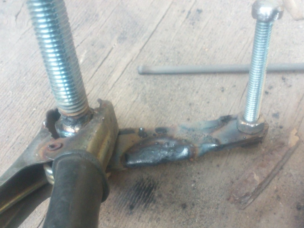
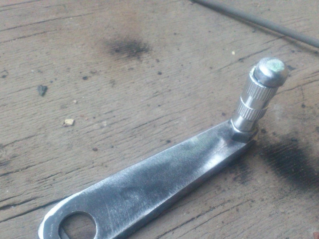
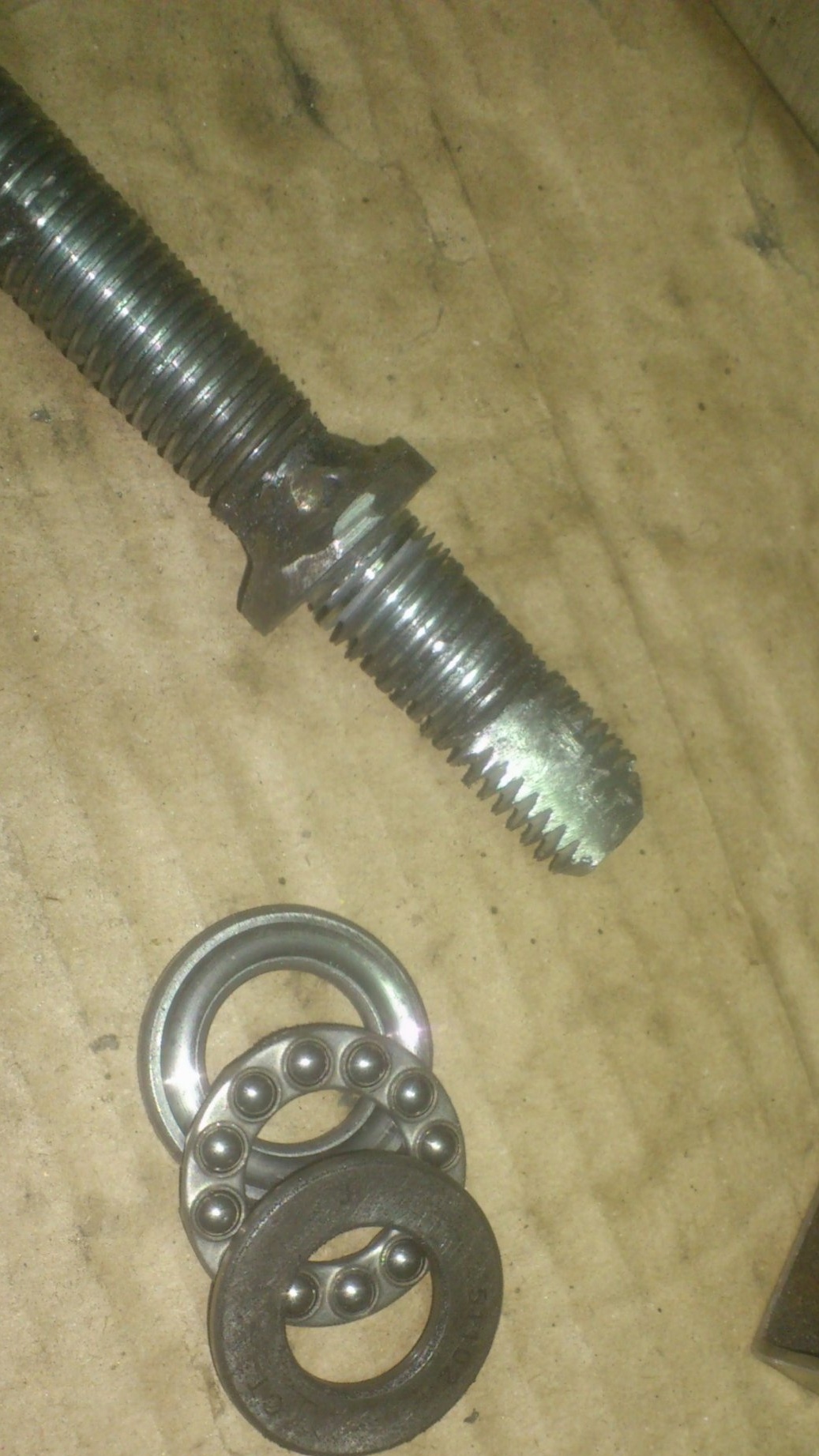
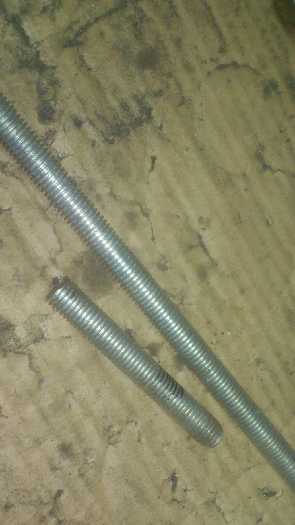
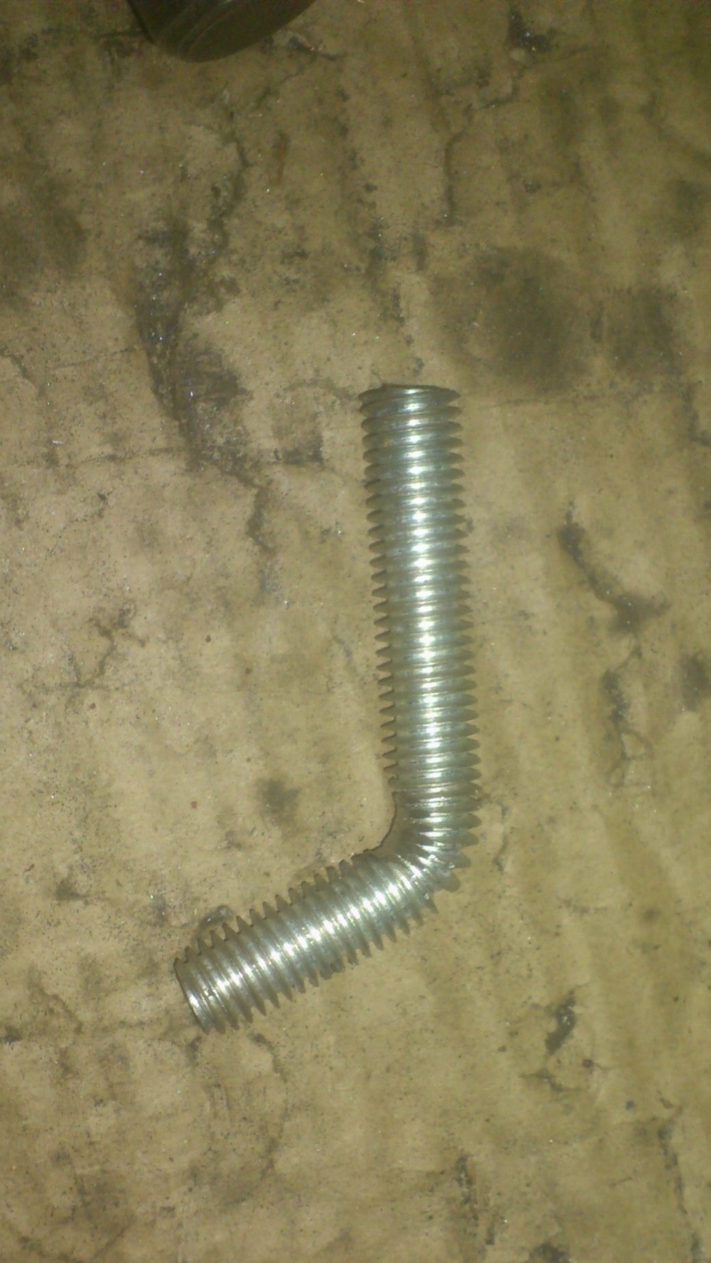
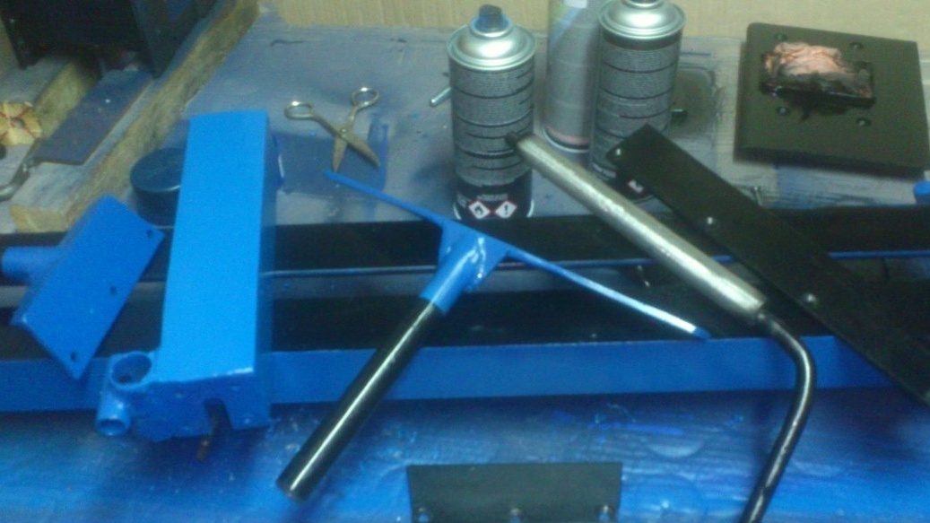
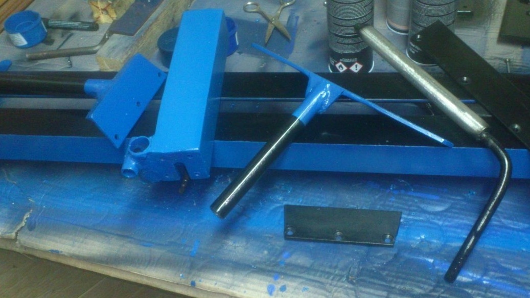
The housing is ready. Now the working (clamping) screw. I made it from the M14 hairpin:
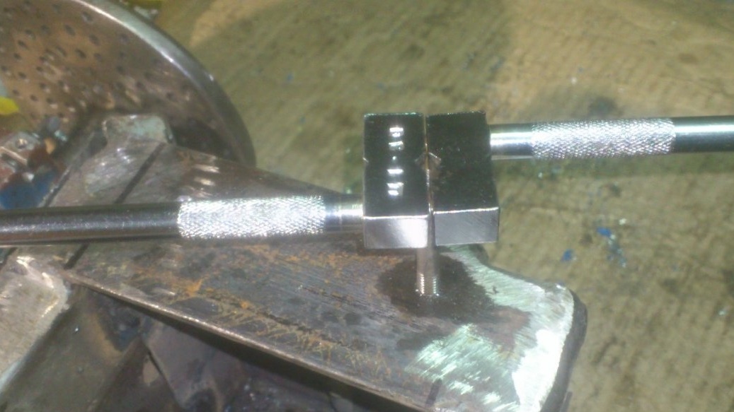
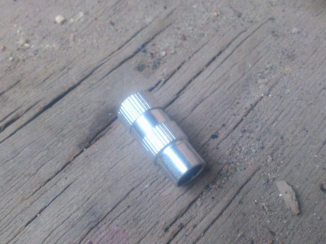
I will rotate it with the help of a handle, which I made of scraps of iron and ... some kind of shiny tube.)))). I don’t know what it is from and how it came to me. Lies about a long time. Metal.
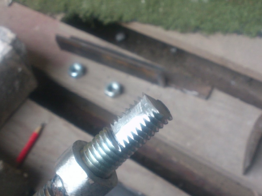
To stop the screw, I made a cover for the back of the casing from the pipe trim 40 to 40, drowning the end in it and drilling holes:
Between it and the support ring of the screw will be placed support bearing:
The principle, I think, is understandable ... When the screw rotates by the handle, it will be screwed in and out of the nut, pushing, or retracting the pin.
For a smooth ride, I placed inside the pintles a piece of sewn polyethylene water pipe:
Then he scored pieces of thick steel wire in the corners for the entire length:
They "dented" the pipe into the threads of the studs, pre-lubricated with silicone grease.After that, with the help of a screwdriver, I drove the hairpin back and forth several times, finally forming a thread of durable cross-linked polyethylene inside the quill for its entire length. This to some extent contributes to a decrease in backlash and the course of the pintles has become significantly smoother.
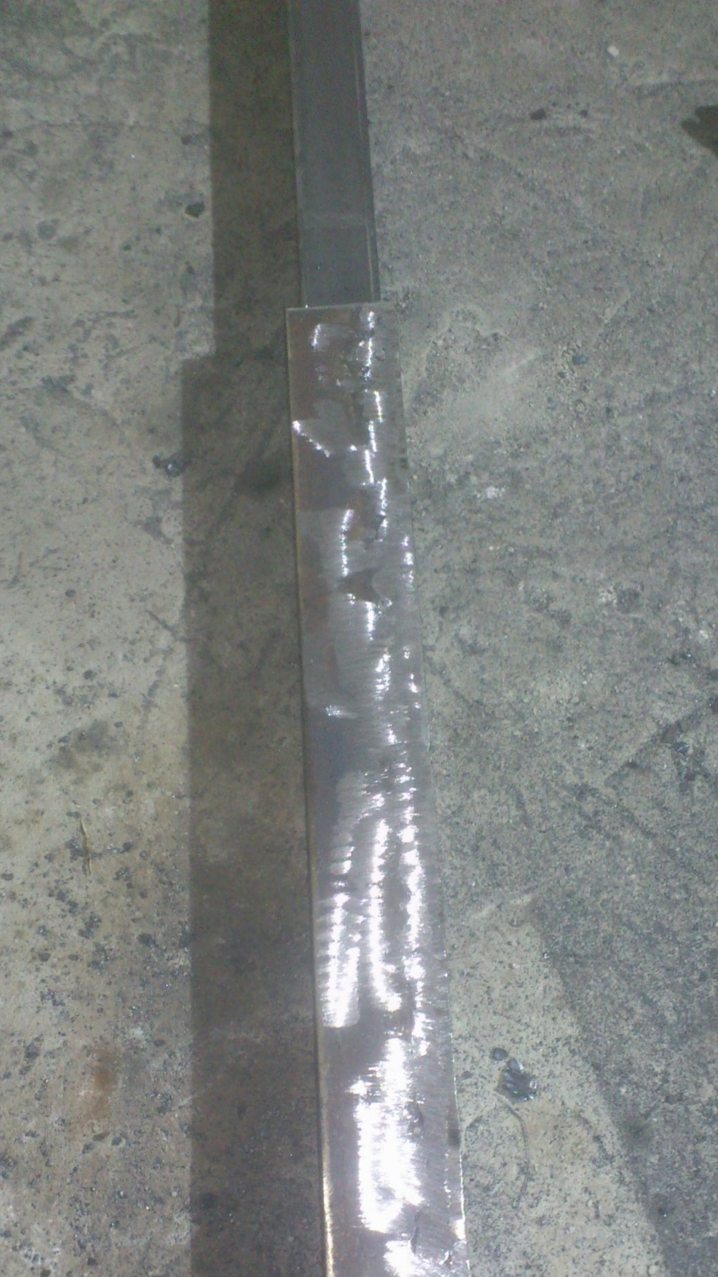
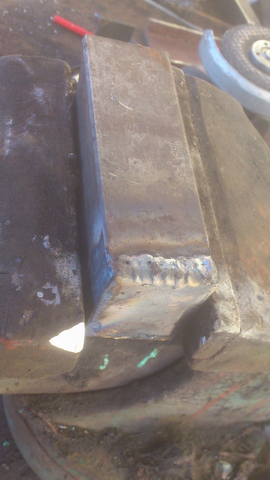
In the front part (where the rotating center will be installed, I strengthened the quill, scald the outside with 5 mm thick steel strips:
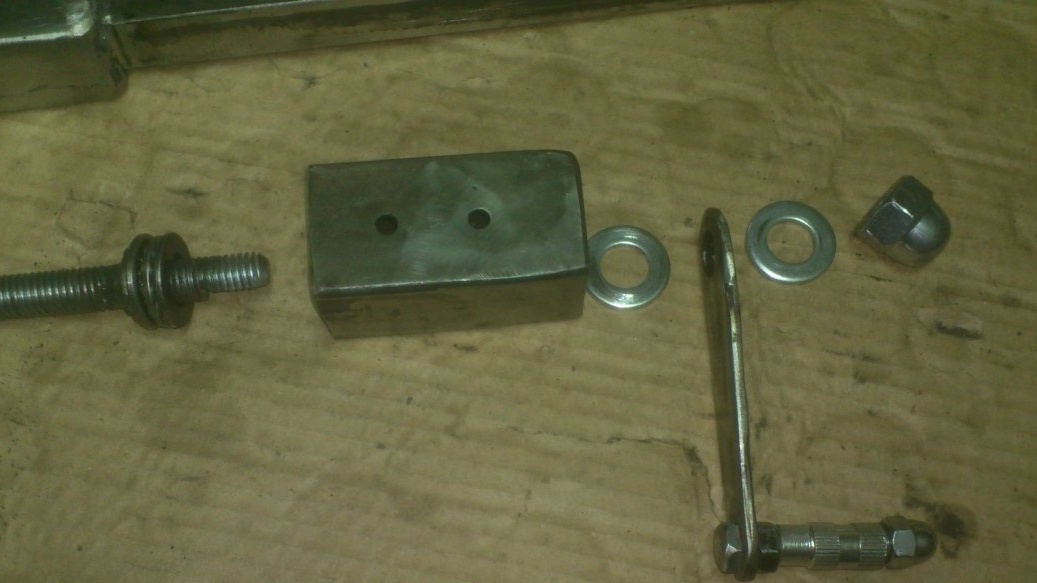
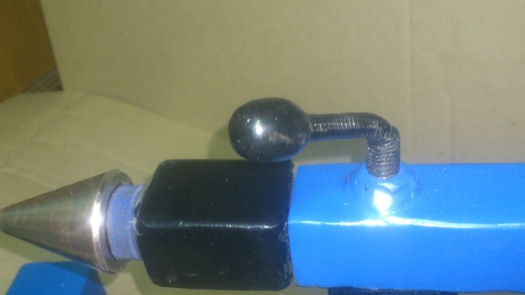
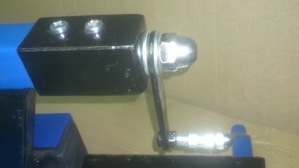
I decided to fix the pinol from spontaneous loosening in the "classical" way - the clamping screw located on top. I drilled a hole in the body and welded a nut. And the screw itself was made from a piece of an M10 pin and a cap nut.
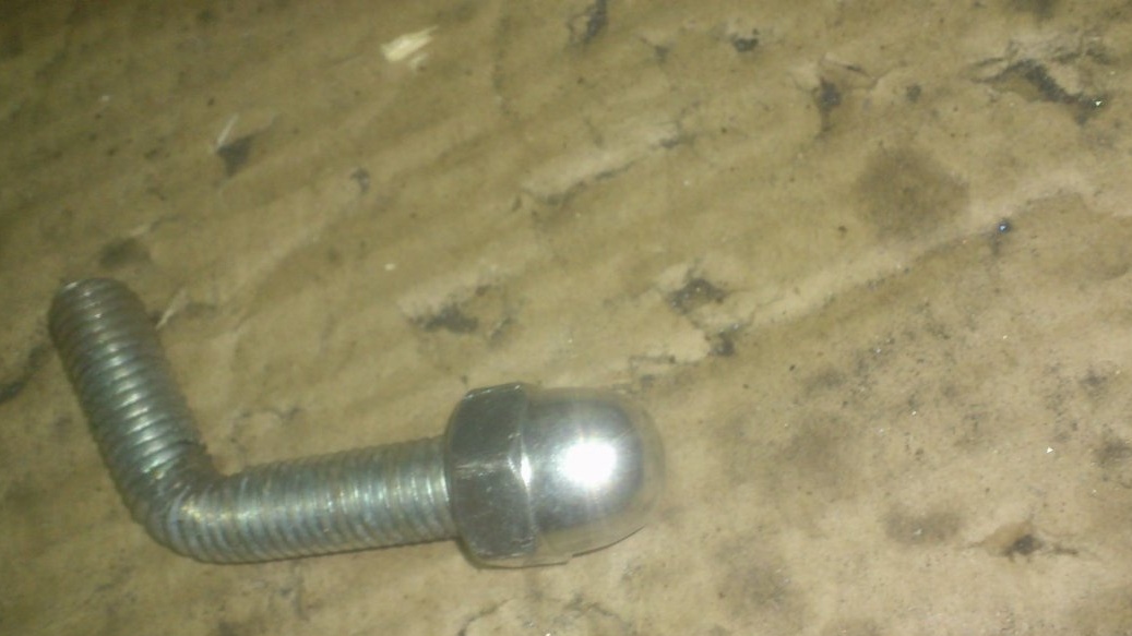
Later I turned the nut into an egg shape. (Will be visible in the final photo).
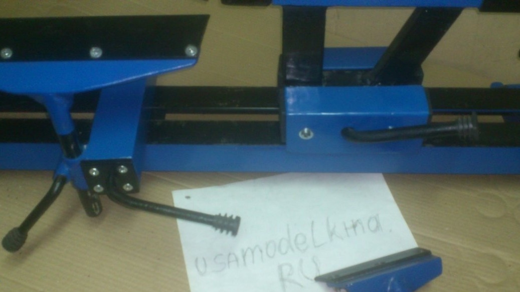
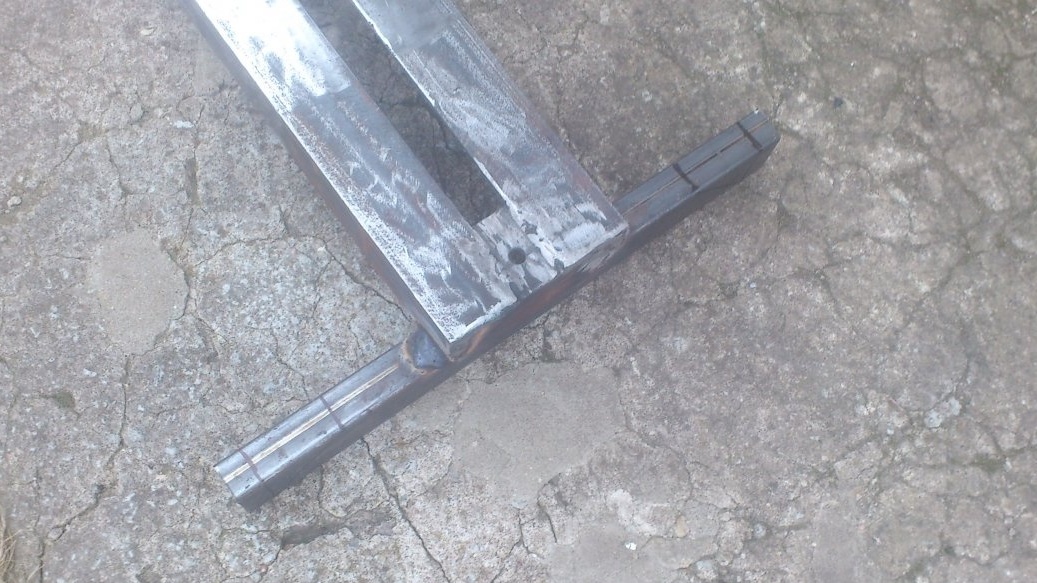
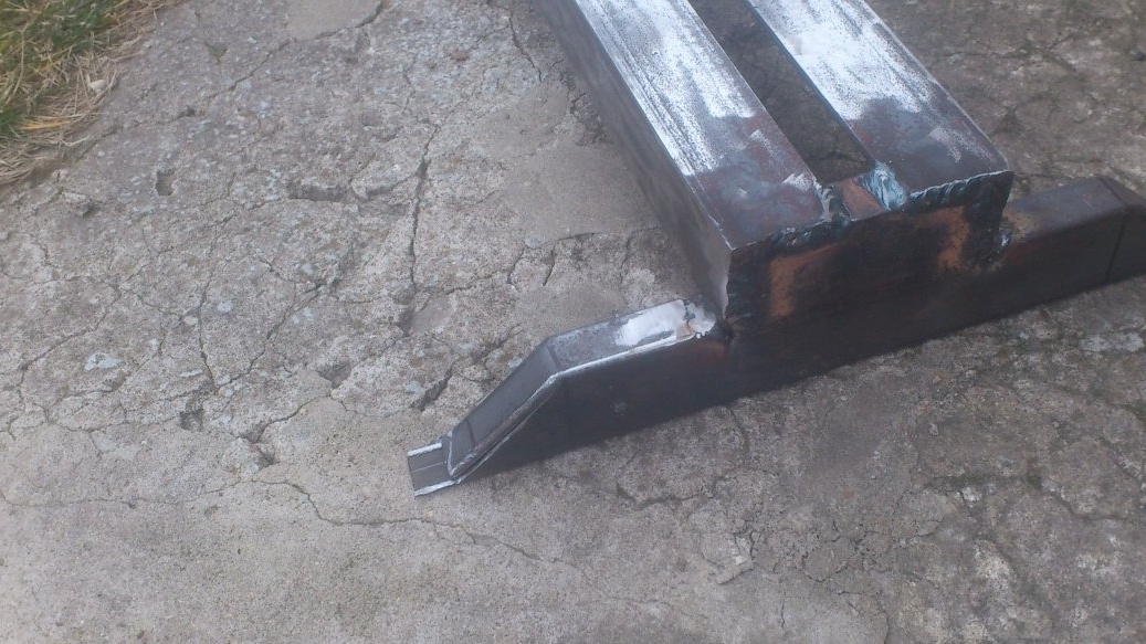
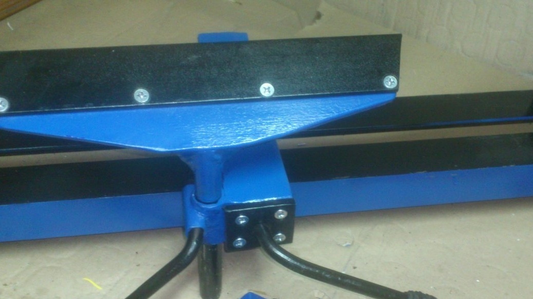
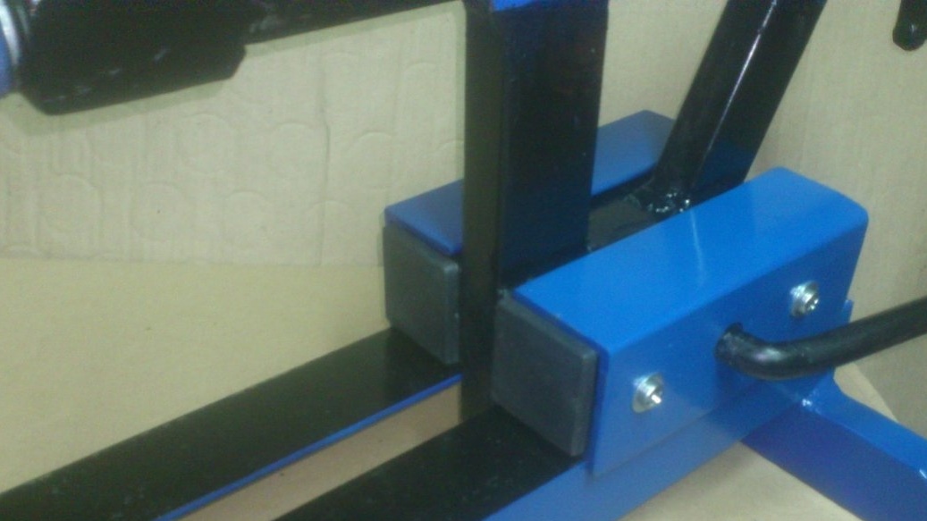
I fixed the pin with the help of two “legs” from the profile pipe 25 to 40 mm. At the same time, the front one was welded at a right angle, and the rear one was tilted. This will give additional rigidity, and will allow for a full rollback of the tailstock to get more working space:
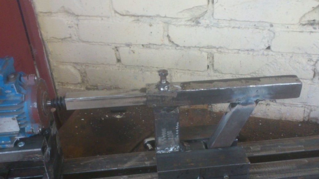
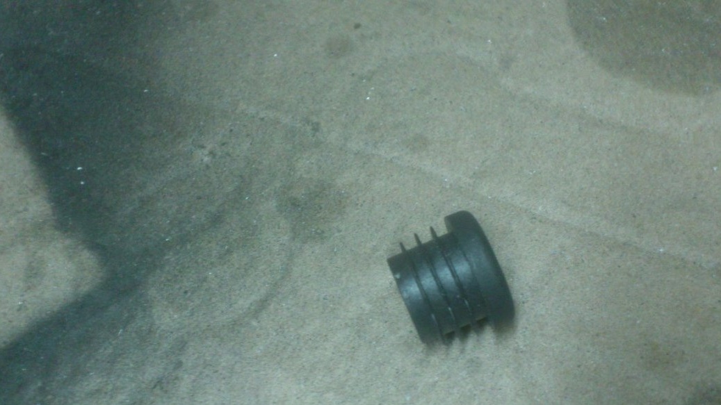
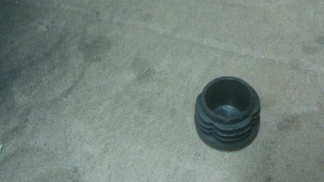
I noticed that the plastic plug for the ДУ15 pipe fits very tightly on the motor shaft, and its cap fits tightly into the pinoli pipe. He put it on the shaft, pulled a pin on it, and setting as far as possible, alignment, welded the “legs” to the “sole”.
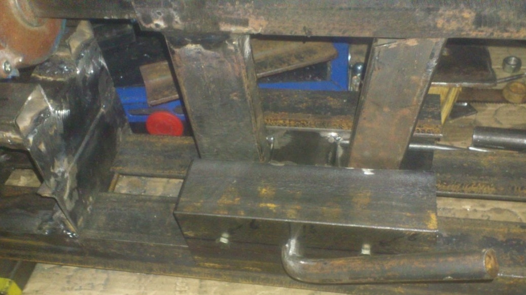
At the same time, while making the machine bed, it was not for nothing that I inserted a profile pipe with a side of 25 mm between the supporting corners. Now the ends of the “legs” of the tailstock protruding from its lower plane fit tightly into this slot and ensure its parallelism to the bed.
I forgot to mention earlier ... The photo above shows that on the bottom of the "sole" I, using M6 bolts with countersunk hats, secured two steel strips of 50 by 5 mm. This is to fine-tune the position of the pintles, since it is not possible to achieve the required accuracy during welding operations of sufficiently massive structures. Putting the washers under the bolts of one "ski", I first achieved an exact horizontal match, and then, operating with the front ones, "pulled up the nails in the correct height, and then put the whole structure in alignment.
(Do not think, there wasn’t much need for the washers there))) Some bolts - without them at all, but under one - three.))))
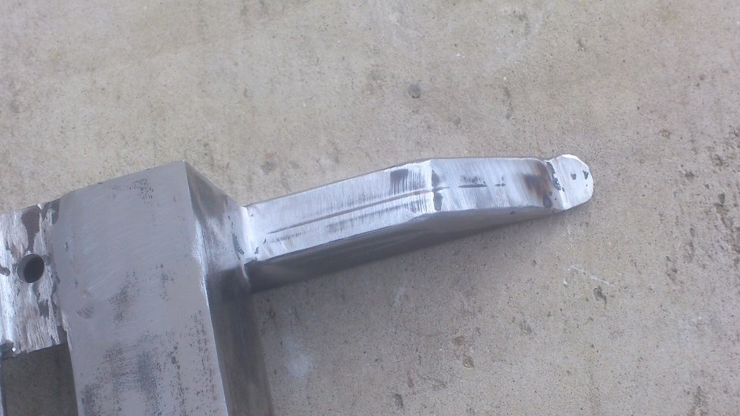
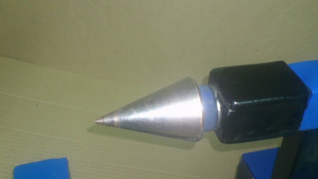
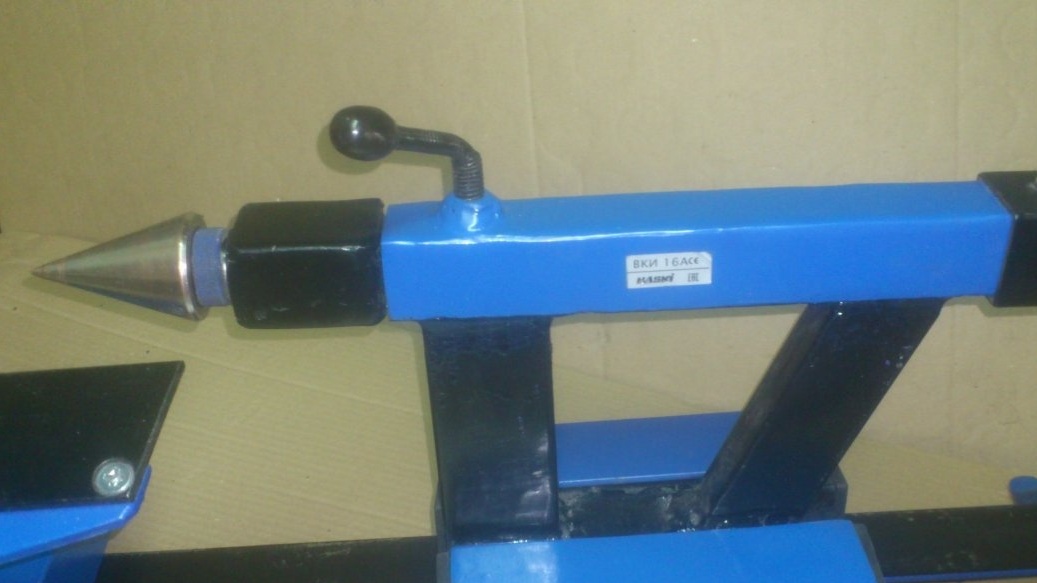
But that was later. After I equipped the quill with a rotating center.
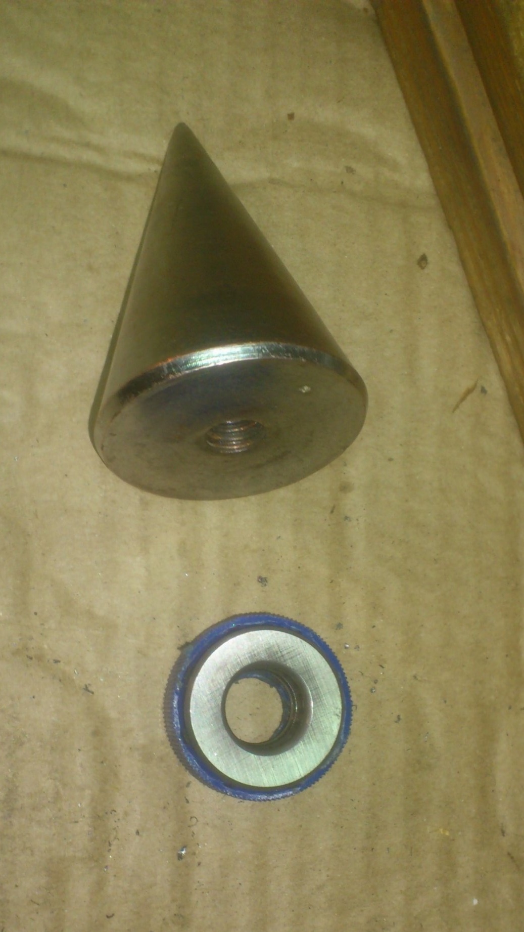
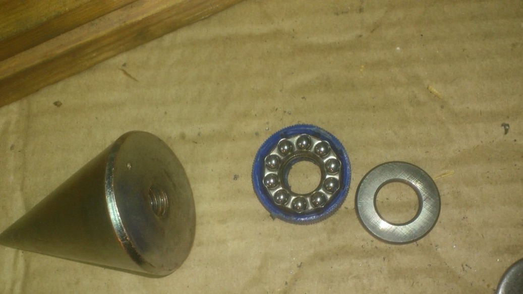
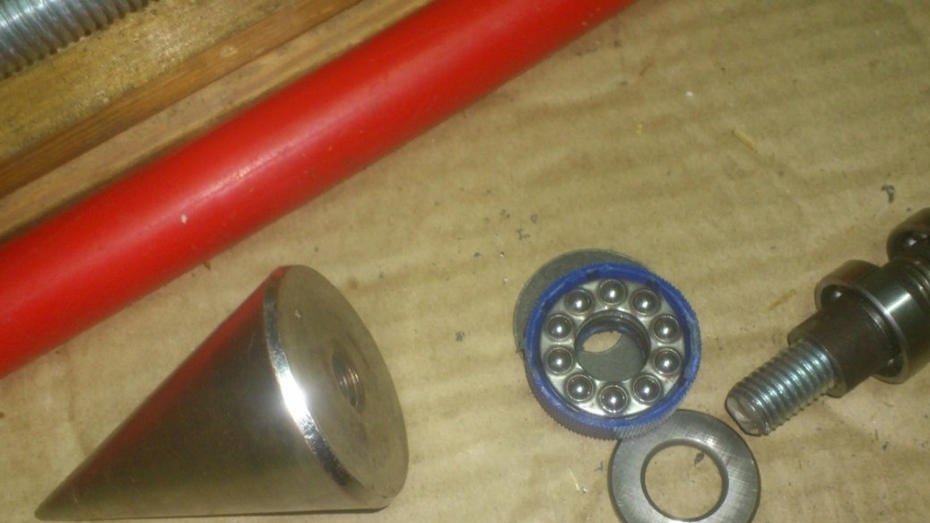
As a working cone of the center, I used a construction plumb. A cork with a hole for the thread was screwed into it. I threw the cork:
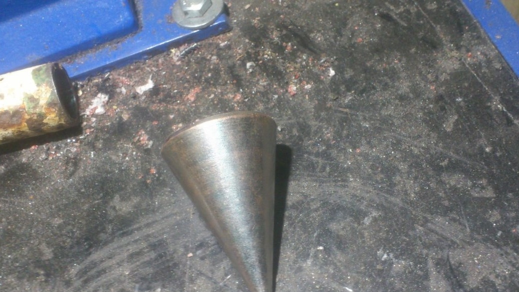
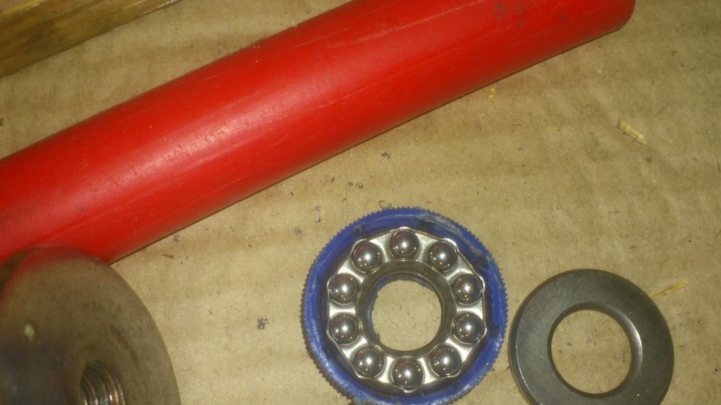
As an axis, I used an M10 bolt, on which I put on sized bearings (Inner - 10 mm, outer - 22 mm), dividing from pieces of tube ДУ8:
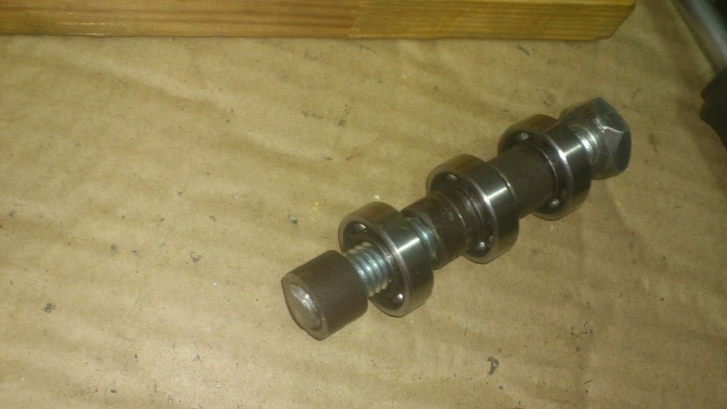
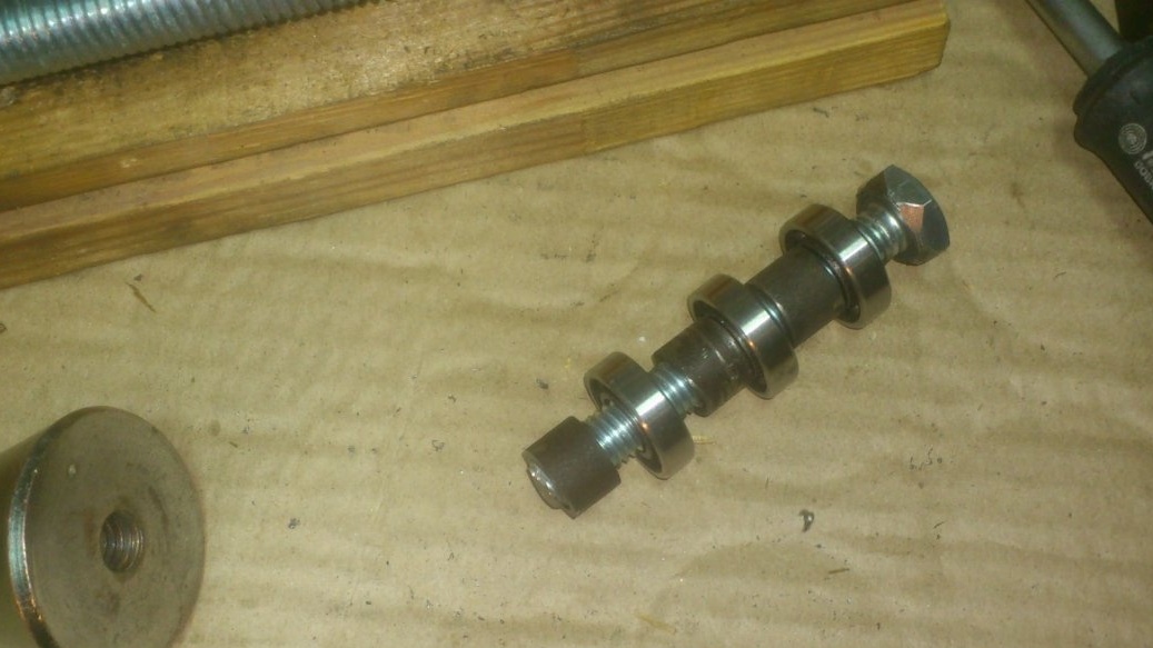
Having placed a support bearing between them and the cone (I used a plug from a PET bottle as a body for it), I screwed the bolt into the cone, coated the thread with glue (so that it could not be twisted on the reverse):
The bearings, as I already seem to have written, are selected in such a way that they fit very tightly into the pins of the profile pipe. Rolling the tailstock forward, inserted the resulting center, and, rotating the handle, pressed the bearings into place.
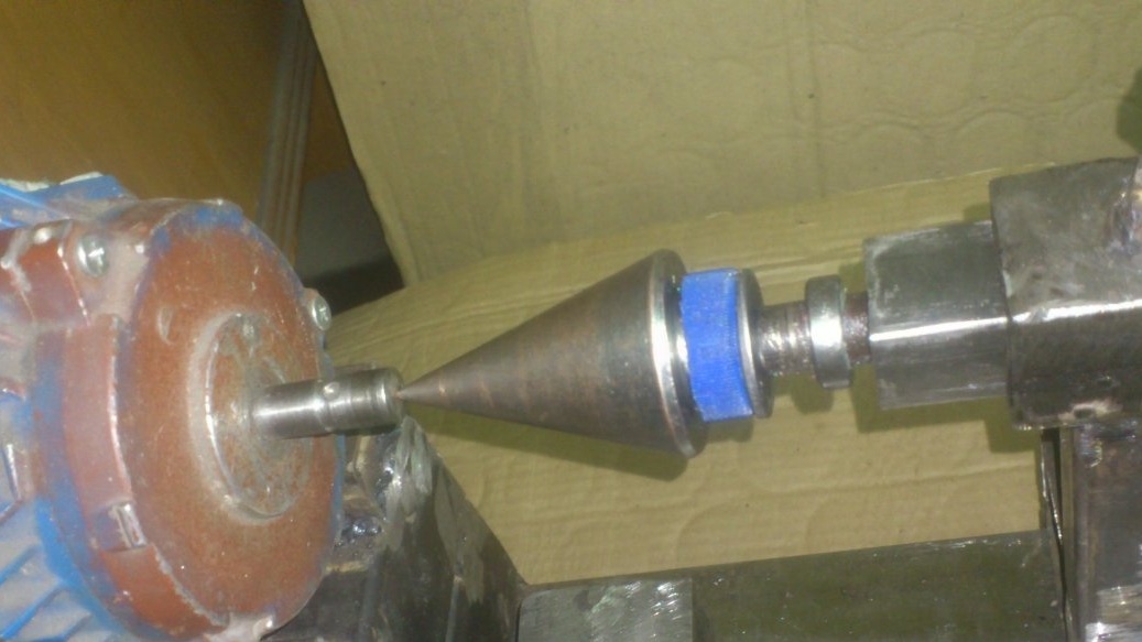
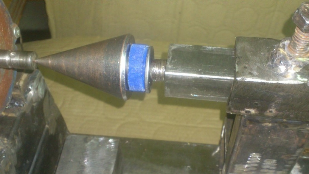
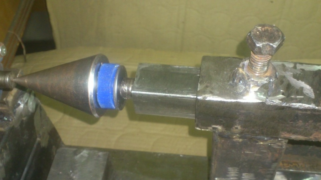
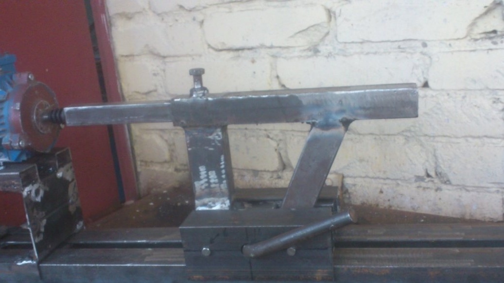
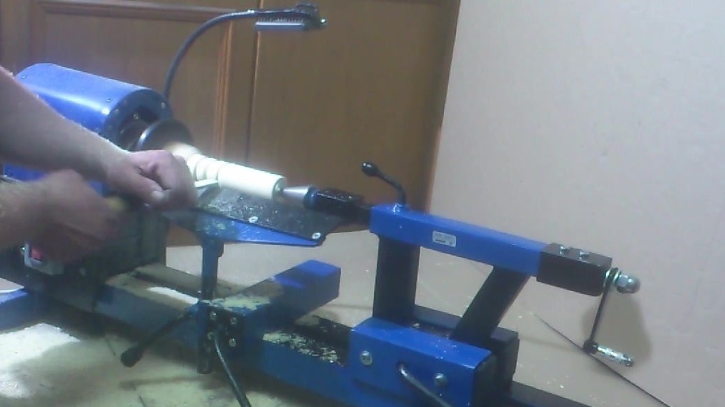
Well then ... Almost done. I tried to sharpen, using the grandfather chisel instead of incisors:
Sharpen normally.)))
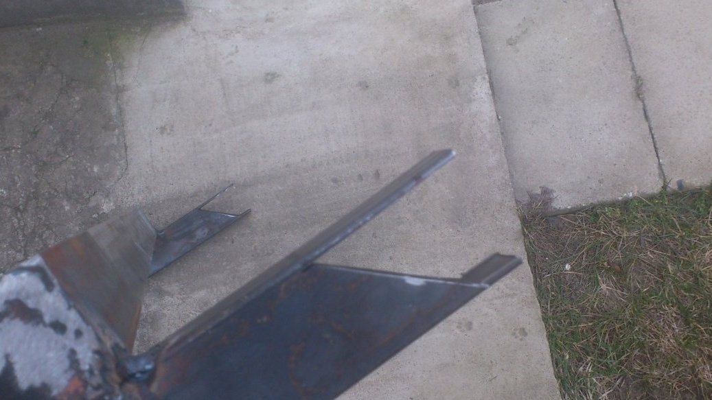
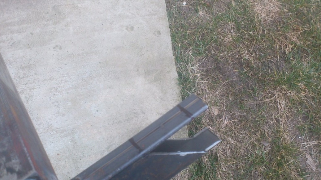
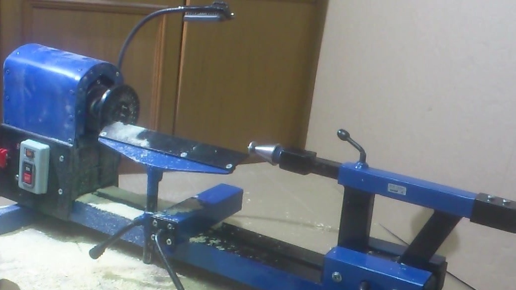
All! It remains to "comb"! )))). We weld the transverse "legs" -pads made of a profile pipe to the bed:
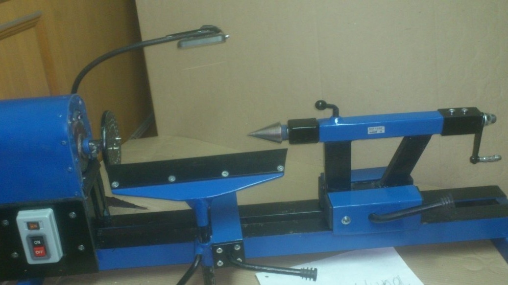
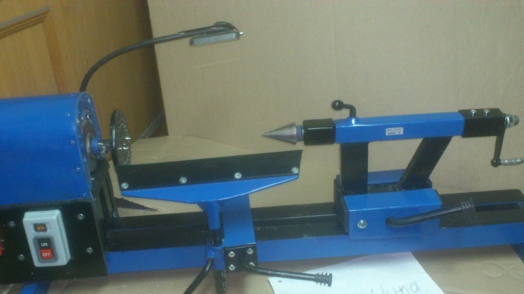
We disassemble. We clean it! We paint!
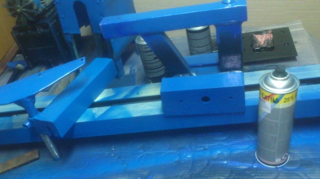
Putting it back:
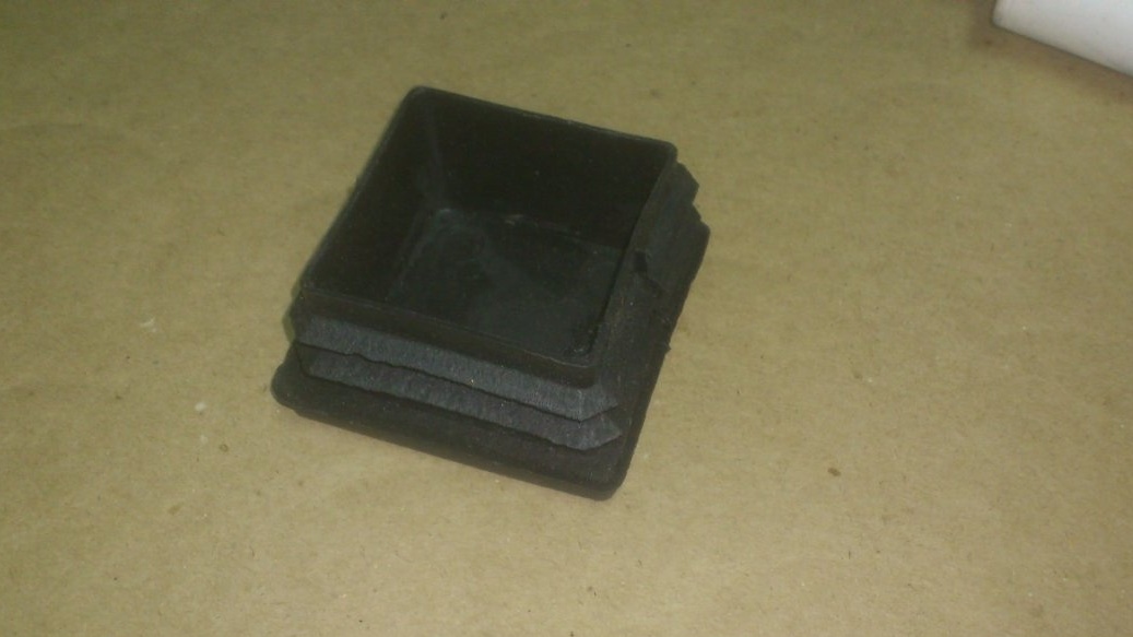
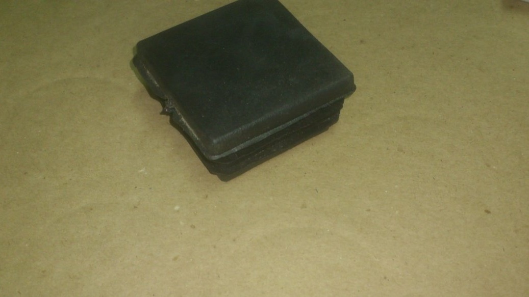
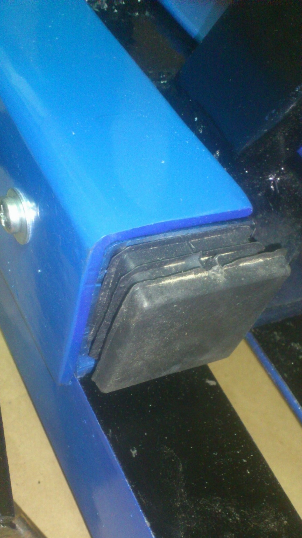
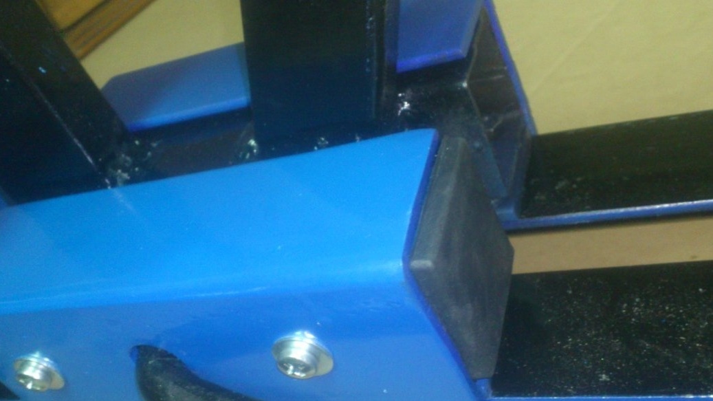
In the open ends of the pipes we hammer in plastic plugs:
When assembling, we use only new hardware:
I made the backlight on a flexible bracket, according to the technology by which I did lamp. Fortunately, I found another piece of the casing from the parking brake cable.
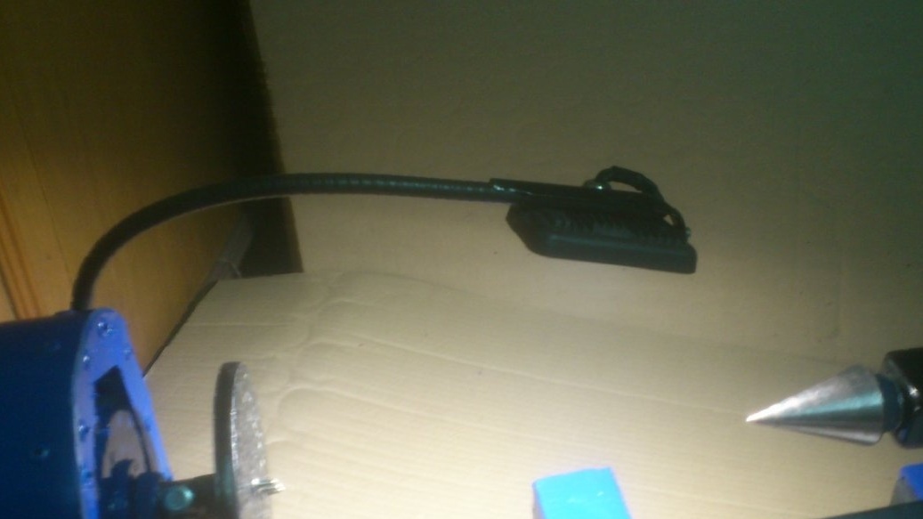
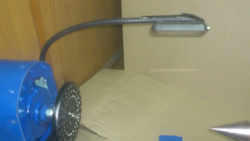
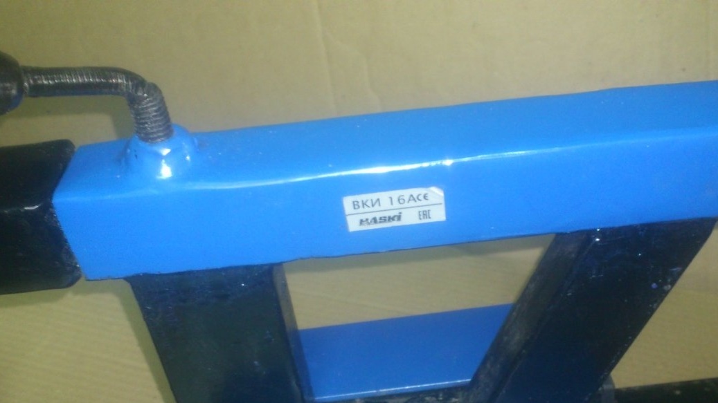
By the way, when I cut the backlight switch into the main switch case, I chose the place where the sticker was. Having removed it, I glued it to the tailstock .... Now, you must admit, it is there to the place!

I could not resist ...))) I immediately tried to sharpen something:
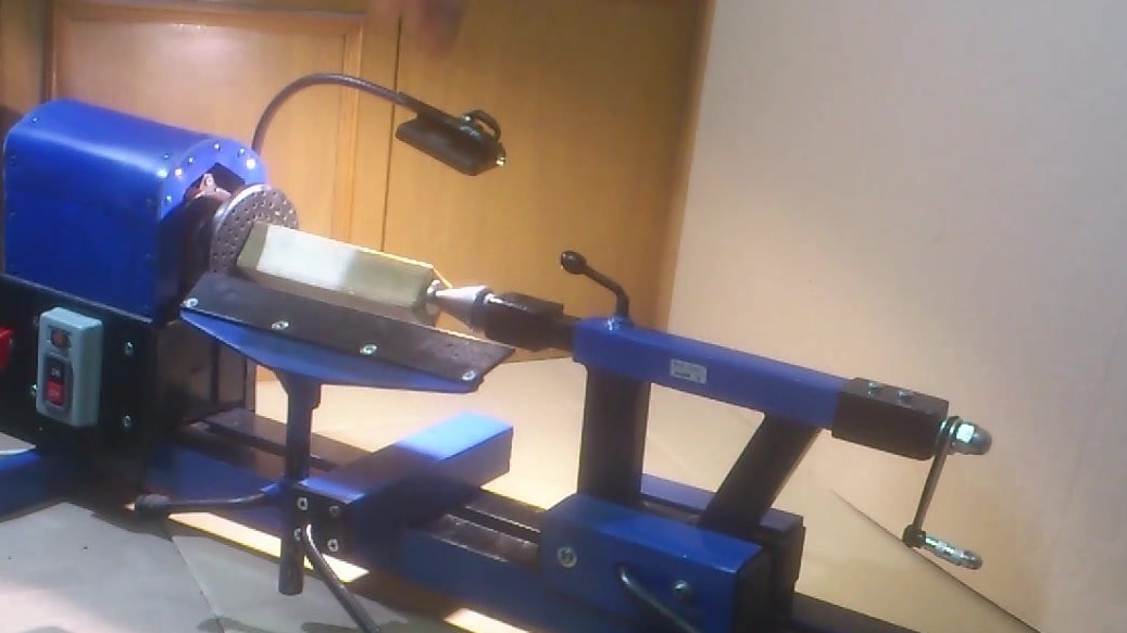
"Something" made! )))):
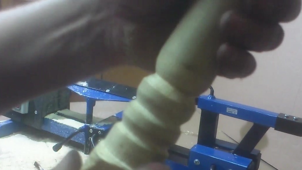
Although there are no incisors yet. I used my grandfather's chisel so far:
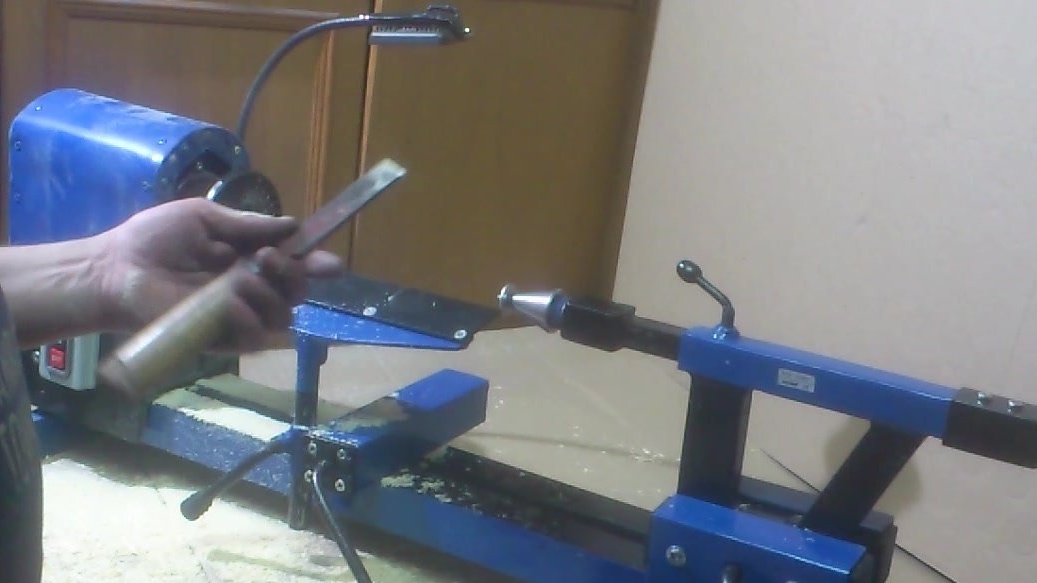
Here's the little stitch I got: