» Electronics » Arduino »Spot Welder on Arduino

Arduino Spot Welder


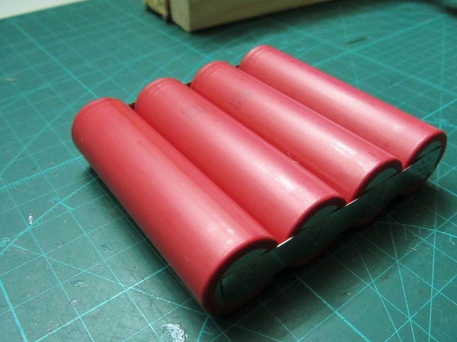
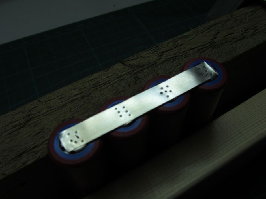
This spot welder can be used to weld 18650 Li-ion batteries. To do this, you need a 7-12V power supply (12V recommended), which is used as a battery from a 12V car. Typically, one 45A \ hour battery is enough to provide enough current to get good welds. Nickel strips 0.15mm thick are welded. For thicker nickel strips, you may need a more powerful battery or you can connect two in parallel.


How the device works

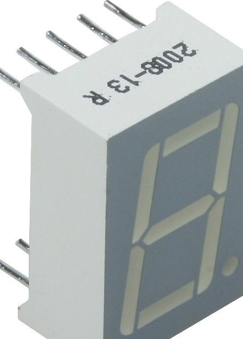
The device generates a double pulse. The first impulse is 1/8 of the time of the second. The duration of the second pulse is adjusted using a potentiometer and displayed on the screen in milliseconds, so that you can fine tune the time. Its duration is adjustable in the range from 1 ... 20 milliseconds. The video shows a more detailed assembly process of the welding device.


All printed circuit boards in the archive in the format of the program “Eagle”.


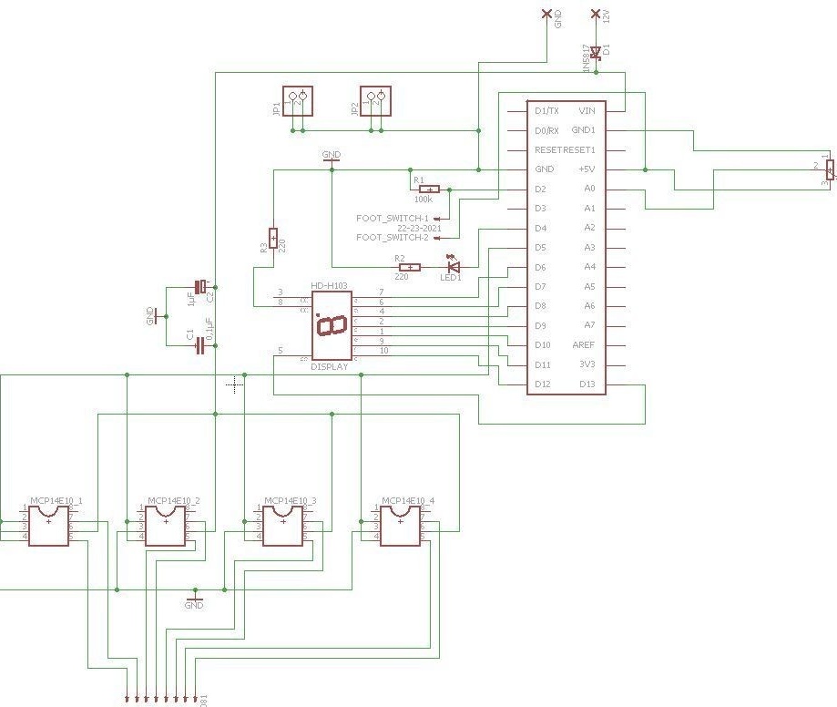
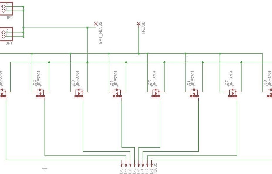
Schematic diagram of the device


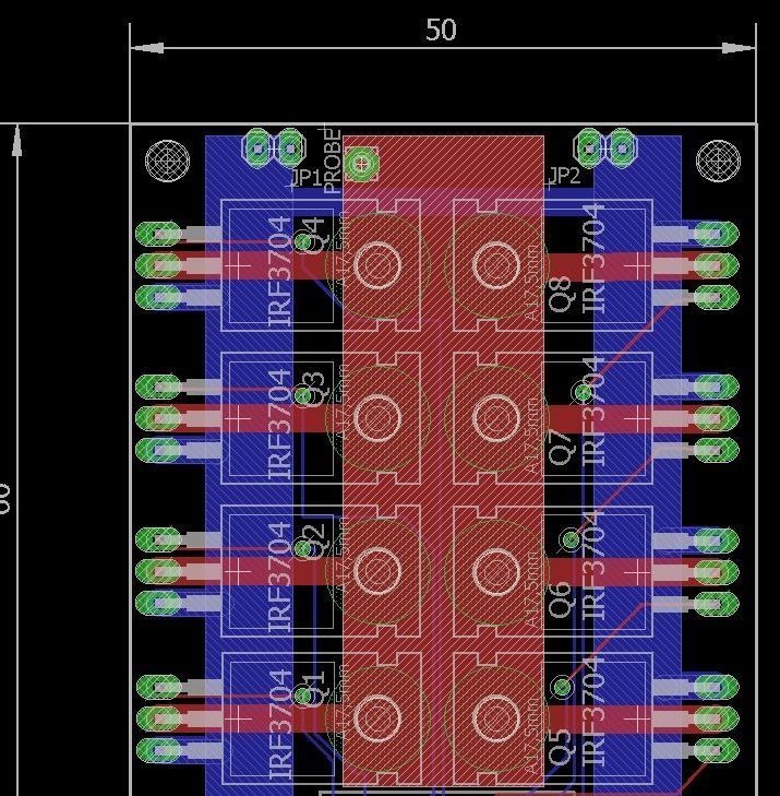
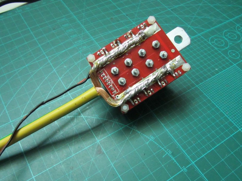
Power Key Circuit Board


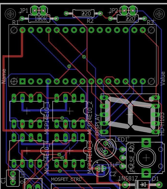
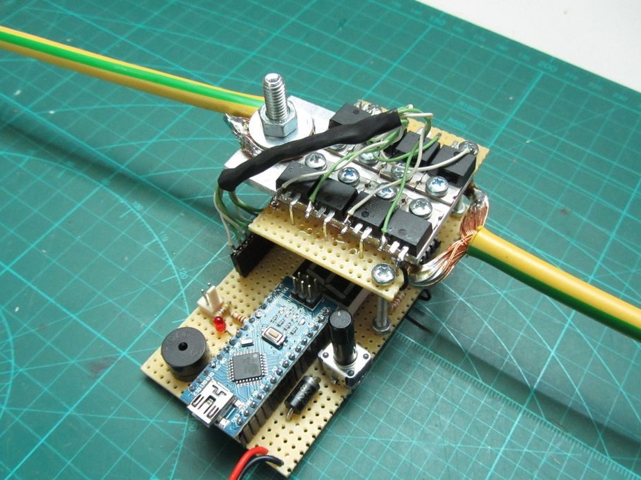
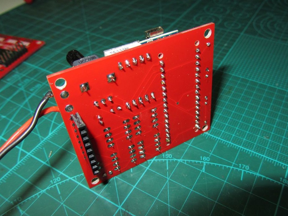
The circuit board of the device itself
You can download the program
In the device, to facilitate assembly, the author does not use parts in SMD cases. Start assembling with small parts.

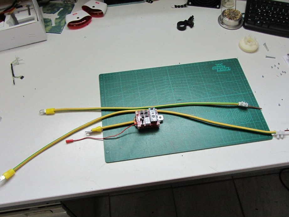
Welding nozzles are made of a copper core with a cross section of 10 sq. Mm,

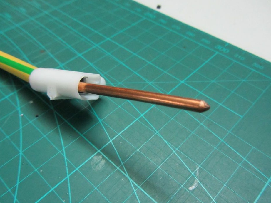
Connecting cable - copper, stranded cross-section of 16 sq.cm.

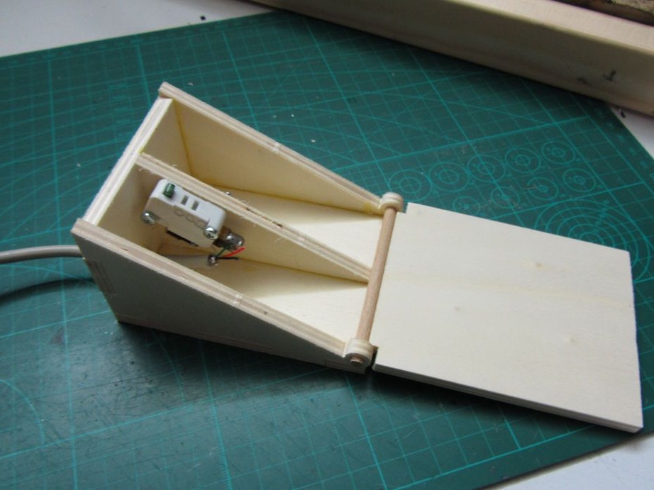
To work with the welding machine, two hands are needed to hold the parts to be welded together. It is necessary to make a foot switch. The author made it from a small wooden box.


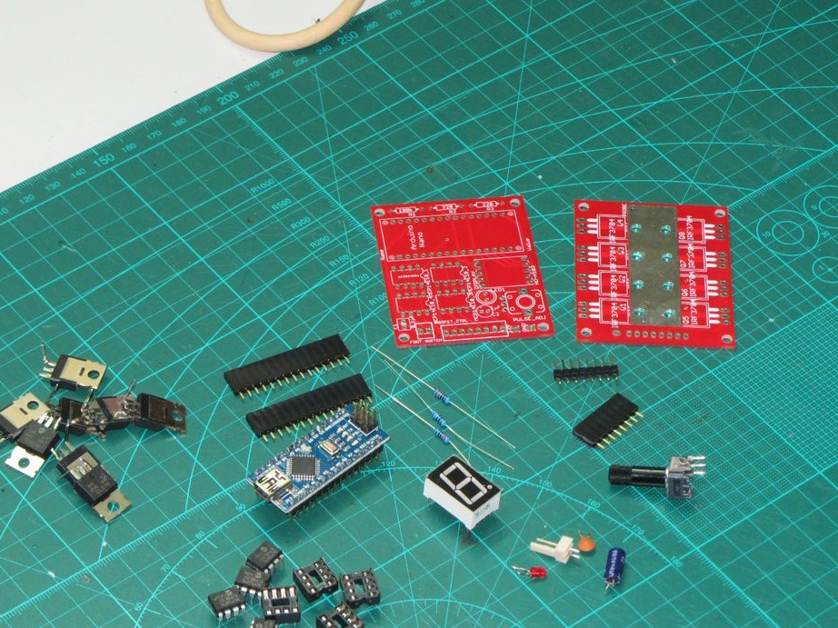
What is needed for assembly:

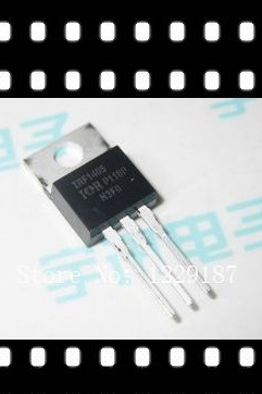
Transistors -, on Aliexpress for $ 6 for 5 pcs
Arduino Spot Welder


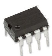
Drivers for these transistors - MCP 14E10-E / P (4 pcs) on Aliexpress did not find,


Vertical Variable Resistor RK09K113-LIN50K (50K 1pc)

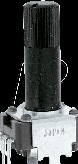
Not necessarily just such a resistor, you can use any 50k variable, but then it will have to be moved outside the printed circuit board.

(1 PC)


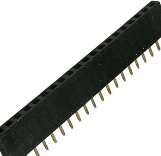
Sockets for drivers (4 pcs)
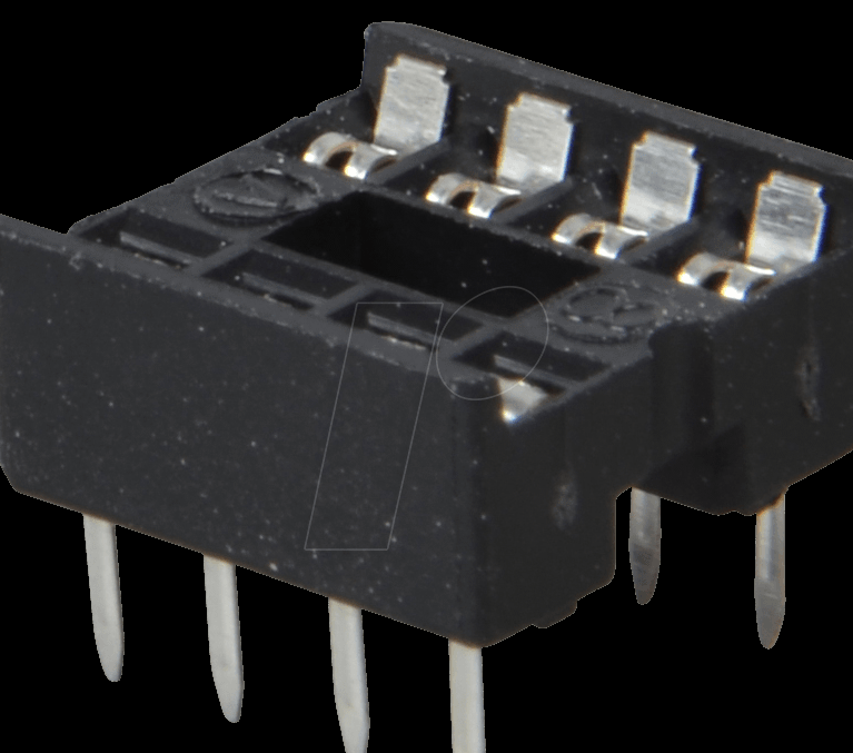


Or such

Single diode 1N5817
One 1mkF / 63v electrolytic capacitor, one 100pF ceramic capacitor, two 221 Ohm and 100K resistors, one 5mm green LED.

Aluminum plate with dimensions 16x70x5 mm

Photos of the finished device in two versions - on the breadboard and on the board ordered on the Internet


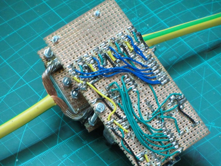
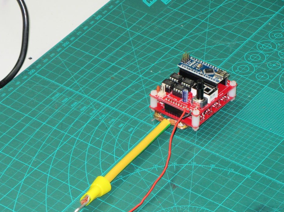
In the archives, printed circuit boards and firmware for the welder
eagle_schematics_and_boards.zip [98.88 Kb] (downloads: 833)
arduino_spot_welder_prowivka.rar [17.29 Kb] (downloads: 944)
10
9.5
9.3

Add a comment

    • smilesmilesxaxaokdontknowyahoonea
      bossscratchfoolyesyes-yesaggressivesecret
      sorrydancedance2dance3pardonhelpdrinks
      stopfriendsgoodgoodgoodwhistleswoontongue
      smokeclappingcraydeclarederisivedon-t_mentiondownload
      heatirefullaugh1mdameetingmoskingnegative
      not_ipopcornpunishreadscarescaressearch
      tauntthank_youthisto_clueumnikacuteagree
      badbeeeblack_eyeblum3blushboastboredom
      censoredpleasantrysecret2threatenvictoryyusun_bespectacled
      shokrespektlolprevedwelcomekrutoyya_za
      ya_dobryihelperne_huliganne_othodifludbanclose
5 comments
In fact, yes, a year has passed .. But I still succeeded:

Moreover, I screwed a very convenient self-timer on a custom timer when you touch.
Now, as you can see from the video, the pedal is not needed. But you can turn on the mode with it, if you really want to.
In the video caption, I didn’t write about why I still haven’t done a review, and the circuit of the end device ..

And what about the power unit and what transistors? How is everything going?
In spot welding, the clamping force and the shape of the electrode ... and the number of Js for heating are of great importance. If you press harder (manually) and with a blunt electrode, there will be a pulse with a large current. This is not an ice for transistors (keys)!
To create a simple impulse use. Arduin - entertained. A simple single-pulse generator, but at least it works on a 555 timer.
Yes, a year has passed, and no one will tell you.
He himself tried to assemble this circuit - the result is the same: the power unit.
I redid the circuit for indication by the 1602 display and with the adjustment of the number of pulses and their duration to a large extent .. But something went wrong with the power unit.
Arduinovskaya works fine. Here are the preliminary LED tests:
https://www.youtube.com/watch?v=GGYPd2XYOm8
In general, I used even higher-current transistors irfb7430pbf, but they with a larger input capacitance, maybe this is the case .. (but this driver is 3 A - it should pull) or maybe (most likely) in Chinese spare parts, but so far the drivers are burning then transistors ..

Initially, in general, out of 5 ordered drivers, only 3 came in whole. I had to send this video to the seller, only then and after pulling a week and a half, he still returned half the cost: https://www.youtube.com/watch?v=-DurSvj-9rI

Has anyone really done exactly THIS scheme?
Does anyone have the same option as in the author’s video? Answer me ..
I took a regular soldering iron, and soldered these jumpers))

We advise you to read:

Hand it for the smartphone ...